Limited Warranty
(Valid only in U.S.A., Canada, Puerto Rico, and the Caribbean.)
Lutron will, at its option, repair or replace any unit that is defective in materials or manufacture within one year after purchase. For
warranty service, return unit to place of purchase or mail to Lutron at 7200 Suter Rd., Coopersburg, PA 18036-1299, postage pre-paid.
THIS WARRANTY IS IN LIEU OF ALL OTHER EXPRESS WARRANTIES, AND THE IMPLIED WARRANTY OF
MERCHANTABILITY IS LIMITED TO ONE YEAR FROM PURCHASE. THIS WARRANTY DOES NOT COVER THE COST OF
INSTALLATION, REMOVAL OR REINSTALLATION, OR DAMAGE RESULTING FROM MISUSE, ABUSE, OR DAMAGE FROM
IMPROPER WIRING OR INSTALLATION. THIS WARRANTY DOES NOT COVER INCIDENTAL OR CONSEQUENTIAL DAMAGES.
LUTRON’S LIABILITY ON ANY CLAIM FOR DAMAGES ARISING OUT OF OR IN CONNECTION WITH THE MANUFACTURE,
SALE, INSTALLATION, DELIVERY, OR USE OF THE UNIT SHALL NEVER EXCEED THE PURCHASE PRICE OF THE UNIT.
This warranty gives you specific legal rights, and you may have other rights which vary from state to state. Some states do not
allow the exclusion or limitation of incidental or consequential damages, or limitation on how long an implied warranty may last,
so the above limitations may not apply to you.
Lutron, Claro, Diva, and Maestro are registered trademarks and FASS
and Satin Colors is a trademark of Lutron Electronics Co., Inc. NEC is a
registered trademark of the National Fire Protection Association, Quincy,
Massachusetts.
© 2010 Lutron Electronics Co., Inc.
Lutron Electronics Co., Inc.
7200 Suter Road
Coopersburg, PA 18036-1299, U.S.A.
Made and printed in U.S.A.
10/10 P/N 030-1367 Rev. A
• Easy-to-follow
Instructions
• Instructions
faciles à suivre
• Easy-to-follow
Instructions
• Instructions
faciles à suivre
030-1367
Important Notes - Please read before installing.
1. CAUTION: Use only with permanently-installed incandescent or 120 V halogen fixtures.
To avoid overheating and possible damage to other equipment, do not use to control
receptacles, fluorescent lighting fixtures, low-voltage lighting fixtures, motor-driven
appliances, or transformer-supplied appliances.
2. Install in accordance with all national and local electrical codes.
3. DO NOT use Maestro
®
dimmers for compact fluorescent (Energy Saver) lamps.
4. Dimmer requires separate wires in the wallbox for each light circuit.
5. Do not use for lights switched from two or more locations (3-Way or 4-Way).
6. When no “grounding means” exist within the wallbox then the NEC
®
2005, Article 404-9
allows a dimmer without a grounding connection to be installed as a replacement, as long as
a plastic, noncombustible wallplate is used. For this type of installation, cap or remove the
green ground wire on the dimmer and use an appropriate wallplate such as Lutron’s Claro
®
or Satin Colors
TM
series wallplates.
7. For new installations, install a test switch before installing the dimmer.
8. Protect control from dust and dirt when painting or spackling.
9. Unit will not operate with less than 40 W of load on each channel.
10. It is normal for the dimmer to feel warm to the touch during operation.
11. Clean dimmer with a soft damp cloth only. Do not use any chemical cleaners.
12. Operate between 0 °C (32 °F) and 40 °C (104 °F).
13. Recommended wallbox depth is 2.5” (64 mm) minimum.
Multigang Installation
When combining controls in a wallbox, remove all inner side sections before wiring (see below).
Use pliers to bend each side section up and down until it breaks off. Repeat for each side
section to be removed. Reduction of dimmer capacity is also required. Refer to chart below for
maximum capacity.
Break Side Sections
Dual Incandescent Dimmer
MA-L3L3
Rated at 120 V~ 60 Hz 300 W per dimmer
English
Do Not Remove Outside Sections
Inside Sections Are
Removed From Each
Control
Dimmer Capacity Chart
Side Sections Are
Removed From Both
Sides Of Middle
Control
?
Technical Assistance
If you have questions concerning the installation or operation of this
product, call the Lutron Technical Support Center. Please provide
exact model number when calling.
U.S.A. and Canada (24 hrs/7days)
1-800-523-9466
Other countries (8am – 8pm ET)
+1-610-282-3800
Fax +1-610-282-3090
http://www.lutron.com
ON
OFF
ON
OFF
ON
OFF
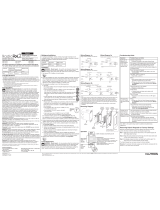
Installation
For installations involving more than one control in a wallbox, refer to
Multigang Installation before beginning.
Separate wires are required in the wallbox for each light circuit.
1
Turning OFF power.
• Turn power OFF at circuit breaker (or remove fuse).
For new construction go to step 5.
2
Removing wallplate and switch.
• Remove the wallplate and switch mounting screws.
• Carefully remove switch from wall (do not remove wires).
3
Verify application.
• This dimmer controls two lights independently. Independent
wires must be provided for each light.
4
Disconnecting switch wires.
Important Note: Your wall switch may have two wires attached to
the same screw (see illustrations below for examples). Tape these
two wires together before disconnecting. When wiring, connect
wires to the Dimmer the same way they were connected to the
switch.
5
Wiring the Control.
• Connect the tagged wire
removed from the switch to
the black screw terminal on
the Control.
• The top brass screw
terminal (Dimmer Channel 1)
is controlled by the top set
of buttons. Determine which
wire should be controlled by
the top buttons and connect
it to this screw terminal.
• Connect the remaining wire
removed from the switch to
the remaining brass screw
terminal (Dimmer Channel 2).
• Use wire connectors to
connect the green ground
wire on the Control to the
bare copper or green
ground wire in the wallbox,
and to cap any unused
wires.
Lutron Technical Support Center 1-800-523-9466 24 hrs / 7 days www.lutron.com
• Tag the wire that is connected
to the
f
eed side
of the switch
(the side with the breakoff fin).
Identify Side with
Break-off fin
Tag
Brass
screws
Black
screw
Green
Wire
Tag
Ground
Wire
6
Mounting Control(s) to wallbox.
• Form wires carefully into wallbox, mount and align control(s).
• Install the wallplate(s).
ON
OFF
ON
OFF
ON
OFF
7
Turning ON power.
• Turn power ON at circuit breaker
(or replace fuse).
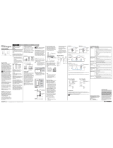
Operation
Light Level Tap Buttons
• Tap once when lights are off -
Lights brighten smoothly to preset
intensity.
• Tap once when lights are on -
Lights dim smoothly to off.
• Tap twice quickly - Lights brighten
rapidly to full intensity.
• Press and hold when lights are on -
Activates delayed fade to off mode. As
the tap button is held, the LEDs will begin
to flash. The first flashing LED represents
a 10 second fade to OFF. Each additional
flashing LED represents an additional 10
seconds of delay before lights fade OFF
(up to 60 seconds delay).
Light Level LEDs
• Indicates approximate
light level.
LEDs may not change
with each press.
Press to increase light level
Press to decrease light level
Troubleshooting
Symptoms
Light does not work or no LEDs
turn on.
Top and bottom switches
control wrong load.
Dimmer behaves erratically
Tap switch does not work at
brightest level.
Possible Causes
• Light bulbs burned out.
• Breaker is off or tripped.
• Dimmed Channel not connected to load.
• Front Accessible Service Switch (FASS) on
Control is pulled out to the OFF position.
• Wires going to the 2 brass screws are reversed.
• Live wire is connected to a brass screw. Fix wiring error
to ensure FASS removes power to both loads.
• Load is less than 40 W.
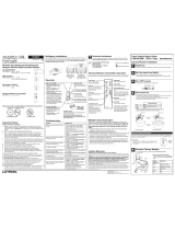
FASS
TM
- Front
Accessible
Service Switch
IMPORTANT NOTICE:
To replace a bulb,remove power by pulling the
FASS
switch out on the Control.
F
or any procedure
other than routine bulb replacement, power must be
disconnected at the main electrical panel.
Brass
Brass
Live
Black
Neutral
Tag
Ground
Light
Light
120 V~
60 Hz
• If you prefer the top and
bottom dimmers to operate
the same lights as before,
note which output wires go to
the top and bottom switches
and install them in the same
relative positions in Step 5.
To learn about the
A
dvanced Features
of
Maestro
®
Dimmers including locked preset and adjustable fade
times, please visit:
w
ww.lutron.com/maestro/advfeatures
or call the
Lutron
Technical Support Center
at 1-800-523-9466.
Dimmer Channel 1
Dimmer Channel 2
Important Wiring Information
Trim or strip wallbox wires to the
length indicated by the strip gauge
on the back of the dimmer.
Push-in Terminals:
Insert wires fully.
NOTE: Push-in
terminals are for use
with 14 AWG solid
copper wire only. DO
NOT use stranded or
twisted wire.
Screw Terminals:
Tighten securely.
Screw terminals are
for use with 12 or 14
AWG solid copper
wire only. DO NOT
use stranded or
twisted wire.
OR
Danger:
Verify that power to
e
ach
switch is OFF before proceeding.
Caution:
Do not overtighten
mounting screws.
Snap on Claro
wallplate.
Start screws.
Screw Terminals:
T
urn screws to loosen.
Push-in Terminals:
Insert screwdriver. Pull wire out.
One wire in the push-in
terminal and one to the
screw.
One continuous wire to
the screw.
Align control and
tighten screws.
Load
Incandescent
120 V Halogen
No Side
Removed
300 W / 300 W
1 Side
Removed
250 W / 250 W
2 Side
Removed
200 W / 200 W
To verify the control is correctly wired, test to make sure that each dimmer is working properly.
If any unexpected behavior occurs, check the troubleshooting guide.