Page is loading ...

1
4 SeriesTM
Processor
H4P5-H48-CE, H4P5-H48-HRL-CE
H4P5-CE, H4P5-HRL-CE
12 V 50 Hz 30 VA
English Español Français Português Deutsch NederlandsItaliano
Please Read Before Installing
Installation Instructions
Overview
The 4 Series Processors, model numbers H4P5-H48-CE,
H4P5-H48-HRL-CE, H4P5-CE, and H4P5-HRL-CE, have
three (3) configurable communication links allowing con-
nection of HomeWorks Wired Keypads, HomeWorks
Wired Maestro
®
Local Lighting Controls, and HomeWorks
Wallbox Power Modules. Model numbers H4P5-H48-
HRL-CE and H4P5-HRL-CE have an additional dedicated
link for Hybrid Repeaters, allowing expansion to RF
devices. The central processor provides lighting presets,
astronomic timeclock events, security mode, vacation
mode, conditional logic, and all other HomeWorks pro-
gramming functions.
A maximum of 10 seeTouch
TM keypads (equivalent to 150
LEDs) may be powered by Link 6 on the 4 Series
Processor. To power additional keypads, or to use
keypads on Links 4 or 5, an additional power supply is
required (Lutron model #s TU240-15DC-9-BL (U.K.) and
TE240-15DC-9-BL (Europe)).
The dedicated Hybrid Repeater Link (Link 8) on H4P5-
H48-HRL-CE and H4P5-HRL-CE processors can provide
power to Hybrid Repeaters. Each Hybrid Repeater counts
as 30 LEDs towards the maximum of 150 LEDs.
Important Notes
Codes: Install in accordance with all local and
national electrical codes.
Power: Two separate power inputs exist on this
processor:
1. Processor power is provided by the 2 conductor
harness that is integral to the HWI-LV24-CE
enclosure. The processor is powered when the
green LED labeled “PWR” is on.
2. Keypads connected to Link 6 are powered by the
supplied plug-in adapter connected to the power
jack labeled “Link 6 15 V ”. Link 6 is powered
properly when the green “LINK PWR” LED is on.
If the red “LINK SHORT” LED is on, Link 6 or 8
are shorted (between terminal 1 and 2) or
overloaded (exceeding 150 LEDs).
Both Processor power and Link 6/8 power must be
present for the processor and keypads to function
properly.
Processor Power: 12 V 50 Hz 30 VA
Link 6/8 Power: 15 V 900 mA NEC Class 2;
IEC PELV
Use only the adapter provided by Lutron with
the 4 Series Processor (Lutron model #s
TU240-15DC-9-BL (U.K.) and TE240-15DC-9-
BL (Europe)).
Environment: Ambient operating temperature:
0-40 °C, 32-104 °F, 0-90% humidity, non-condensing.
Indoor use only.
Cleaning: To clean, wipe with a clean damp cloth. DO
NOT use any chemical cleaning solutions.
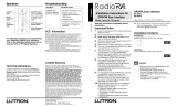
H4P5-H48-CE H4P5-H48-HRL-CE
Figure 1 - 4 Series Processors and Adapters
H4P5-CE H4P5-HRL-CE
U.K. Plug-in Adapter
TU240-15DC-9-BL
Input: 220-240 V 50 Hz 19 W
Output: 15 V 900 mA
IEC PELV; NEC Class 2
Europe Plug-in Adapter
TE240-15DC-9-BL
Input: 220-240 V 50 Hz 19 W
Output: 15 V 900 mA
IEC PELV; NEC Class 2

2
Installation
4. Connect to HomeWorks lighting controls. For the
H4P5-H48-CE and H4P5-H48-HRL-CE models only,
connect the communication wiring from the HomeWorks
Maestro® Dimmers to the factory installed Dimmer Hub
(HWI-H48-CE). See Figure 4, page 3. Connect the buses
according to the bus assignments that were made using
the HomeWorks Illumination Software. Gray and violet
connections are marked on the printed circuit board.
5. Connect Dimmer Hub links: For the H4P5-H48-CE and
H4P5-H48-HRL-CE model only, an internal harness con-
nects Link 4 to the factory installed Dimmer Hub. If addi-
tional HWI-H48-CE or HWI-Q96 boards are to be con-
trolled by the processor, the communication link to those
boards should be connected into the Link 4 terminal
block. Do not connect terminal 2 to an HWI-H48-CE or
HWI-Q96. If the H48/Q96 Link has a cable length of 15 m
(50 ft.) or more, LT-1 link terminators must be installed
across MUX and MUX (terminals 3 and 4) at both ends
of the link. Refer to HWI-H48-CE or HWI-Q96 instruc-
tions (see also Figure 5, page 4).
Note - Links 4, 5 and 6 are configurable for use
as Keypad Links, GRAFIK Eye
®/WPM Links, or
H48/Q96 Links. These links are configured by the
HomeWorks Illumination Software.
6. Connect Inter-processor Link (multiple processor
installations only): The Inter-processor Link is used for
communication between HomeWorks Processors.
Connect control wiring to the Inter-processor Link (Link
2), if required. Do not connect terminal 2 (see Figure 5,
page 4). If this processor is to be the first or last
processor in the daisy chain, attach one of the LT-1 link
terminators provided across the MUX and MUX
(terminals 3 and 4—see Figure 5, page 3). If LT-1
terminators are unavailable, a 1/2 W resistor between
100 and 150 Ohms may be placed across terminals 3
and 4 to provide termination.
7. Connect GRAFIK Eye / WPM links: If GRAFIK Eye
preset dimming controls or Wallbox Power Modules are
to be controlled by this processor, connect the
communication wires to Link(s) 4, 5, or 6 as configured in
the HomeWorks Illumination Software. Do not connect
terminal 2.
8. Connect Keypad links: For keypads or keypad link
devices (e.g. HWI-CCO-8) that are to be controlled by
this Processor, connect the communication wires to
Link(s) 4, 5, or 6 as configured in the HomeWorks
Illumination Software. Note: Connecting keypads or
keypad link devices to links other than Link 6 requires an
additional power supply.
9. Connect Hybrid Repeater link: For the H4P5-H48-HRL-
CE and H4P5-HRL-CE models only, connect the Hybrid
Repeater communication wires to Link 8. Note: DO NOT
connect the +15 V terminal (terminal 2) if the Hybrid
Repeater(s) will be powered by the plug-in 9 V adapter
provided with the repeater(s).
10.Connect power. Plug the power input harness terminals
(yellow wires) from the HWI-LV24-CE enclosure onto the
power feed lugs on the 4 Series Processor. Connect plug
from adapter to Link 6 Power connector. Plug adapter
1. Ensure Mains voltage cover in HWI-LV24-CE enclosure is
securely installed. Locate and lock supply breaker in the
OFF position before installing processor assembly.
Danger - Wiring with power on may result in
personal injury.
2. Install processor assembly in the enclosure: The
HomeWorks® 4 SeriesTM Processor is attached to the
HWI-LV24-CE enclosure using four mounting keyholes
and the mounting screws provided.
3. Set processor address. Set processor address using
the Configuration Switch. The HomeWorks Illumination
TM
Software will prompt the programmer if any subsequent
changes to the configuration switches are required (see
Table 2). The factory installed Dimmer Hub (H4P5-H48-
CE and H4P5-H48-HRL-CE only) is already addressed to
“1”.
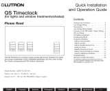
Figure 2 - Mounting
Diagram
The 4 Series Processor mounts
in the upper left corner of an
HWI-LV24 enclosure.
High-voltage enclosure
(shown with cover installed).
Figure 3 - Processor Addressing
DIP Switch Function
1 Boot Mode. Unless prompted by the
HomeWorks Illumination Software, this switch
should always be in the DOWN position.
2 UP = 9600 Baud,
DOWN = User selected Baud.
3-6 Processor Address. See Figure 3, below.
Table 2 - Configuration Switch Functions
Down (OFF)
Up (ON)
Example: Setting Switch #6 ON.
English
Español
FrançaisPortuguês
Deutsch
Italiano
Nederlands

3
Mounting
Keyhole (4
places)
Figure 4 - 4 SeriesTM Processor
To HomeWorks® Wired Maestro® controls
(H4P5-H48-CE and H4P5-H48-HRL-CE
only)
into receptacle in bottom of HWI-LV24-CE. The 4 Series
Processor has battery-backed memory and timeclock
devices. The battery provides power to these devices
during power outages and other temporary power
interruptions. In vacation homes and other residences
which are not continuously occupied, the 4 Series
processor MUST be powered by a circuit that is never
turned off even when the residence is unoccupied.
11.Turn power ON. Restore the supply breaker to the ON
position.
12.Connect Serial Link. Connect a standard DB9 male
connector to the Link 3 RS232 connector on the
processor for system programming or communications
with other equipment. A standard serial cable (not a null
modem) is required for programming the system via the
serial port using a laptop. If the processor is connected
to a modem, a null modem adapter is needed between
the processor and the attached modem.
13.Connect Ethernet Link. Connect a standard RJ45
connector to the Link 9 Ethernet jack on the processor
for system programming or communications with other
equipment. A crossover cable is required for
programming the system via direct connection to a
laptop computer. If plugging into a network, a standard
cable is used (see Figure 4, below). The orange LED
(ACT) will illuminate when there are any Ethernet signals
being transmitted or received on Link 9. The green LED
(CON) will illuminate when the Link 9 is connected to a
hub/switch/router or a computer. For help configuring a
laptop to talk to the processor, see Help in the
HomeWorks Illumination Software.
Dimmer
Hub
(H4P5-
H48-CE
and H4P5-
H48-HRL-
CE only)
To additional
Dimmer Hubs
RS-232 Port
Ethernet Port
English Español Français Português Deutsch NederlandsItaliano
PIN
1
2
3
4
5
6
7
8
9
Name Description
DCD Data Carrier Detect
TXD Transmit Data
RXD Receive Data
DSR Data Set Ready
GND Ground
DTR Data Terminal Ready
CTS Clear To Send
RTS Request To Send
RI Ring Indicate
Pin Processor
1 Transmit +ve
2 Transmit -ve
3 Receive +ve
4 No Connection
5 No Connection
6 Receive -ve
7 No Connection
8 No Connection
Ethernet Hub/Switch
Receive +ve
Receive -ve
Transmit +ve
No Connection
No Connection
Transmit -ve
No Connection
No Connection
1
2
3
4 NC
5 NC
6
7 NC
8 NC
1
2
3
4
5
6
7
8
NC
NC
NC
NC
Crossover Cable
Configuration
A crossover cable is used when
connecting the processor to a
laptop or other non-hub device
(a/v systems, HVAC, etc.)
Processor
Label
Processor
Board

English
Español
FrançaisPortuguês
Deutsch
Italiano
Nederlands
Lutron Electronics Co., Inc.
7200 Suter Road
Coopersburg, PA 18036-1299
Made and printed in the U.S.A. 5/06 P/N 043-207 Rev. A
LT-1 Link
Terminator
LT-1 Link
Terminator
Wiring Detail
LT-1 Link
Terminator
LT-1 Link
Terminator
Wiring Detail
4 Series
TM
Processor
4 SeriesTM
Processor
Pin 1 - 1 1.0 mm
2
(18 AWG)
Pins 3 & 4 - 1 pair 0.5 - 1.0 mm
2
(22-18 AWG)
twisted/shielded for data
Pin 2 is not connected
305 m (1 000 ft.) maximum total wire run distance
8 SeriesTM
Processor
Figure 5 - Daisy Chained HomeWorks® Processors
Technical Assistance
If you have questions concerning the installation or
operation of this product, call Lutron’s European
Headquarters. Please provide exact model number
when calling.
Lutron EA LTD
Lutron House
6 Sovereign Close
Wapping
London, E1 9HW, England
FREEPHONE: 0800 282107 (U.K.)
Tel: +44 (0) 207 702 0657
Fax: +44 (0) 207 480 6899
LIMITED WARRANTY
Lutron EA Ltd. (“Lutron EA”) warrants that each new unit will be free from defects in mate-
rial and workmanship and will correspond with the specifications issued by Lutron EA and
perform under normal use and service. To the extent permitted by law, Lutron EA and
Lutron Electronics Company, Inc. (“Lutron”) make no warranties or representations as to
the units except as set forth herein. This warranty shall run for a period of two years from
the date of delivery and Lutron EA’s obligations under this warranty are limited to remedy-
ing any defect, or replacing any defective part, or replacement of the unit (at Lutron EA’s
sole option), and shall be effective only if the defective unit is shipped to Lutron EA
postage prepaid within 24 months after delivery of the unit, to the extent permitted by law.
After the two year period, a pro-rated warranty applies to the unit until eight years after
delivery of the unit. Repair or replacement of the unit does not affect the expiry date of the
warranty. This warranty does not cover damage or deficiencies due to abuse, misuse,
inadequate wiring or insulation, or installation other than in accordance with instructions
accompanying the unit.
Although every attempt is made to ensure that catalogue information is accurate and up-
to-date, please check with Lutron EA before specifying or purchasing any unit to confirm
availability, exact specifications, and suitability for your application.
This warranty does not affect the statutory rights of consumer purchasers of the unit.
This product may be covered under one or more of the following patents:
In the United States: 5,838,226; 5,905,442; 6,803,728 and corresponding foreign patents.
Lutron, HomeWorks, Maestro, GRAFIK Eye, and the sunburst logo are registered trade-
marks and 8 Series, 4 Series, seeTouch, Illumination, and the HomeWorks 4 Series logo
are trademarks of Lutron Electronics Co., Inc.
© 2006 Lutron Electronics Co., Inc.
/