Page is loading ...

D900-06-00 1 I56-750-58
SS24ADAS Series Strobes and
MASS24ADAS Series Synchronized
Horn/Strobes for Fire Protective
Signaling Systems
INSTALLATION AND MAINTENANCE INSTRUCTIONS
A Division of Pittway
3825 Ohio Avenue, St. Charles, Illinois 60174
1-800-SENSOR2, FAX: 630-377-6495
General Description
The National Fire Protection Association has published
standards and recommended practices for the installation
and use of the listed appliances. It is recommended that the
installer be familiar with these requirements, with local
codes, and any special requirements of the local fire au-
thority having jurisdiction.
The Multi-Alert™ sounder and signaling strobe are intended
to be connected to the alarm indicating circuit of a UL-
listed fire alarm control panel and is compatible with DC
line supervision. The electronic sounder can be connected
to either 12 or 24 VDC panels. Models SS2415ADAS,
SS241575ADAS, and combination models incorporating
these strobes, require 24 volt panels. Panels may have full-
wave rectified, unfiltered power supplies. The strobes are
synchronized and flash at a rate of one flash per second
with continuous voltage applied. SS24ADAS, SS24ADA,
MASS24ADAS, and MASS24ADA series devices may be
combined in the same zone.
Model Supply Operating Current from Operating Current from Full-Wave
Voltage Regulated Supply Rectified Unfiltered Supply
Range
SS2415ADAS 20-30V 106 200 5.0/7.0 125 250 5.0/7.0
SS241575ADAS 20-30V 195 350 5.0/7.0 180 395 5.0/7.0
Average Peak Inrush Average Peak Inrush
Operating Current Current Operating Current Current
Current (mA) (Amps) Current (mA) (Amps)
(mA) 20/30 (mArms) 20/30
Vrms Vrms
NOTE: In-rush current duration is less than 20
microseconds (.00002 seconds).
Table 2. Sound output and current ratings for the MA12/24D:
Sound (Hz) Clips on Current (mA) Output (dBA)
UL (dBA)
UL (dBA)
Tabs DC Regulated/ (Note 3)
Ratings
w/MDL Module
(Note 1) FWR Unfiltered (Note 4) Temp. Tone (Note 5)
12V 24V 30V 12V 24V 12V 24V 12V 24V
Slow Whoop ABC 21/40 38/56 46/72 85 92 79 85 N/A N/A
800 Continuous BC 15/24 28/45 35/55 87 93 79 85 75 79
800/1000 Alternating AC 17/32 34/46 43/58 85 92 79 85 N/A N/A
2400 Interrupted AB 19/23 35/56 43/64 89 90 79 85 N/A N/A
2400 Continuous C 21/31 38/59 46/73 85 94 79 85 75 79
1200 Interrupted B 13/19 23/33 27/41 85 91 75 82 N/A N/A
Swept Frequency A 17/24 34/47 43/60 85 92 79 85 N/A N/A
Fast Warble NONE 15/27 30/47 38/59 85 92 79 85 N/A N/A
Table 1. SS24ADAS Series Electrical Ratings:
Note 1: See Figure 2 for tab clip removal & storage.
Note 2: All models can be powered using full wave rectified unfiltered sup-
plies. Under no circumstances can SS24ADAS or MASS24ADAS se-
ries devices input voltage exceed 33 VDC or be less than 16 VDC
(18-33Vrms for full-wave rectified, unfiltered supplies).
Note 3: Measured at 10 feet in an anechoic chamber.
Note 4: Measured in a UL reverberant room.
Note 5: Only continuous tones (800Hz, 2400 Hz) can be temporally
coded per UL. Strobes cannot be used on an MDL module pro-
viding temporal coding to Multi-Alert™ horns.
The MA12/24D sounder is suitable for outdoor applica-
tions (-35° to 66° C) when it is used with a WBB Weather-
proof Back Box. The signaling strobe is rated for 0° to 49°
C and is NOT suitable for outdoor use.
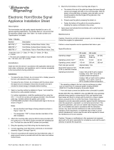
The UL-rated light output of the SS2415ADAS,
SS241575ADAS, MASS2415ADAS, and MASS241575ADAS
is 15 cd (See Figure 1).
NOTE: The light output at 0° viewing angle for
SS241575ADAS and MASS241575ADAS is 75 cd.
Any one of eight sounds can be selected on the electronic
sounder, as indicated in Table 2.
NOTE: SS24ADAS, MASS24ADAS AND MAEH24ADAS SE-
RIES DEVICES OPERATING IN THE SAME ZONE
WILL NOT BE SYNCHRONIZED IF ENERGIZED AT
DIFFERENT TIMES (I.E., IF MORE THAN ONE CON-
TROLLER IS CONTROLLING THE SAME ZONE.)

D900-06-00 2 I56-750-58
The sound selected determines the maximum current and
sound power output per device. SeeTable 2 for these values.
Independent Sounder/Strobe Operation
There may be applications where it is desirable to drive the
sounder and strobe as independent devices. The System
Sensor MASS12/24ADA series sounder/strobes are easily
configured for this capability. The terminal connection for
this application is shown in Figure 6. Independent strobe
operation in a coded system requires a separate uncoded
power supply for the strobe.
Installation - For Strobe Placement, See NFPA 72,
Chapter 6
A. General: Slotted head screws are used to attach each de-
vice or combination of devices to the electrical outlet
box. Phillips head screws are used to attach accessories
to the horn. Refer to Figures 3,4,5, and 6 for wiring
methods.
NOTES: Do not loop wires under the terminal screw. Wires
connecting the device to the panel must be broken
at the device terminal connection in order to
maintain electrical supervision.
Strobe and strobe/horn combination are de-
signed for wall mounting ONLY.
The sounder is 1-1/4" deep. Back boxes must be 4"
square by at least 1-1/2" deep – 2-1/8" deep box is rec-
ommended.
All strobes must be mounted so that the top of the lens is
24 inches (61 cm) below ceilings or as required by the
authority having jurisdiction.
B. Sounder/Strobe combination mounting:
1. Surface Mount: (See Fig. 10)
2. Semi Flush Mount: (See Fig. 11 and 14)
C. Sounder mounting:
1. Surface Mount : (See Fig. 7)
2. Semi Flush Mount: (See Fig. 11 and 14)
3. Flush Mount (See Fig. 13)
Flush mounting requires the use of the deep box (Part
# BB-D) or equivalent. Determine which of the two
device holes will be used to attach the device to the
box. Mount the flush plate to the sounder using the
other two holes with two 1-inch phillips head screws
and two square nuts.
D. Strobe mounting:
1. Surface Mount: (See Fig. 9)
2. Semi Flush Mount (See Fig.12)
Installation procedures must conform to all applicable codes
and the requirements of the authority having jurisdiction.
NOTE: The rated output of the sounder is specified at 10
feet. It cannot be assumed that the output will
meet the NFPA standard of 15 dB over ambient
noise at all locations within a room. Additional
sounders may be needed to ensure sound output
level complies with NFPA requirements.
The Sounder and/or Strobe will not work without power. The sounder/
strobe gets its power from the fire/security panel monitoring the alarm
system. If power is cut off for any reason, the sounder/strobe will not pro-
vide the desired audio or visual warning.
The Sounder may not be heard. The loudness of the sounder meets (or
exceeds) current Underwriters Laboratories’ standards. However, the
sounder may not alert a sound sleeper or one who has recently used drugs
or has been drinking alcoholic beverages. The Sounder may not be heard
if it is placed on a different floor from the person in hazard or if placed too
far away to be heard over the ambient noise such as traffic, air condition-
ers, machinery or music appliances that may prevent alert persons from
hearing the alarm. The Sounder may not be heard by persons who are
hearing impaired.
The Signal Strobe may not be seen. The electronic visual warning signal
that flashes at least once every three seconds meets or exceeds current Un-
derwriters Laboratories’ standard 1971 and uses an extremely reliable xe-
non flash tube. The visual warning signal is suitable for direct viewing and
must be installed within an area where it can be seen by building occu-
pants. The strobe must not be installed in direct sunlight or areas of high
light intensity (over 60 foot candles) where the visual flash might be disre-
garded or not seen. The strobe may not be seen by the visually impaired.
The signal strobe may cause seizures. Individuals who have a positive
photic response to visual stimuli with seizures, such as epileptics, should
avoid prolonged exposure to environments in which strobe signals, in-
cluding this strobe, are activated.
System Sensor recommends that the Multi-Alert Sounder and Signal
Strobe always be used in combination so that the risks from any of the
above limitations are minimized.
The signal strobe cannot operate from coded power supplies. Coded
power supplies produce interrupted power. The strobe must have an unin-
terrupted source of dc power in order to operate correctly.
Synchronized strobes may not prevent photosensitive reactions to signal
strobes in alarm condition.
WARNING
The Limitations of Sounder/Strobes

D900-06-00 3 I56-750-58
NOTE: ALL STROBES THAT ARE TO BE IN SYNC MUST BE ON THE SAME POWER CIRCUIT.
LIGHT
0˚
–45˚
45˚
90˚ –90˚
A78-1137-00
A78-2167-00
Percent of
Degrees Rating
0 100
5 - 25 90
30 - 45 75
50 55
55 45
60 40
65 35
70 35
75 30
80 30
85 25
90 25
MA12/24D
A
B
B
A
BB-STD
A78-1137-03
(-)
IN OUT
STROBE
ONLY
(-)
IN OUT
(+)
IN OUT
STROBE
ONLY
(+)
IN OUT
From
panel or
previous
device
To Next
Device
or EOL
- VDC
+ VDC
A78-1137-01
From
panel or
previous
device
To Next
Device
or EOL
– VDC
+ VDC
Note: Use uncoded suppl
y
onl
y
.
(–)
IN OUT
STROBE
ONLY
(–)
IN OUT
(+)
IN OUT
STROBE
ONLY
(+)
IN OUT
A78-1137-29
CLIP
STORAGE
CLIPS REMOVED OR
ADDED TO SELECT
DESIRED TONE.
COVER SLOT
TAB A
TAB B
TAB C
FOR STORING UNUSED CLIPS:
SLIDE COVER BACK TO ALIGN COVER SLOT
WITH CLIP STORAGE POST.
SLIDE COVER
FOR CLIP STORAGE
USE A
SMALL-
BLADED
SCREWDRIVER
TO REMOVE
CLIPS
TONE
SELECTION TABS
Figure 2: Figure 3. Multi-alert sounder:
Figure 4. Multi-alert sounder and strobe operating in
tandem:
Figure 5. Strobe:
From
panel or
previous
device
To Next
Device
or EOL
– VDC
+ VDC
+ VDC
– VDC
STROBE
SOUNDER
(–)
IN OUT
STROBE
ONLY
(–)
IN OUT
(+)
IN OUT
STROBE
ONLY
(+)
IN OUT
Non-
Coded
Supply
Can Be
Coded
Supply
Caution: Break off P.C.B. Tabs
Figure 6. Multi-alert sounder and strobe operating
independently:
Figure 7. Sounder surface mount:
Figure 1. Vertical and horizontal light distribution:
Screw types used in
Figures 9 to 15
A = 8-32x1-7/16" Slot
B = #8 Sheet Metal Phillips
C = 8-32x1" Phillips
D = #8 Square Nut
E = 8-32x5/8" Slot
F = 8-32x2-3/4" Slot
G = 6-32x5/8" Slot

D900-06-00 4 I56-750-58
© System Sensor 1997
1. Screw plate to box with screw E.
2. Complete field wiring. (See Fig. 3,
4, 5, and 6)
3. Screw sounder or sounder/strobe
to plate with screw A.
4. Fill remaining holes with screw B.
A78-2517-01
1. Screw strobe to plate with
screw C.
2. Complete field wiring.
3. Screw strobe plate to box with
screw A.
A78-2516-00
1. Plaster ring should be properly mounted to electrical box
with screws supplied with box.
2. Screw plate to plaster ring with screw G.
3. Complete field wiring. (See Fig. 5, 7, and 8)
4. Screw sounder/strobe to plate with A.
5. Fill remaining holes with screw B.
A
A
B
B
G
G
MA 12/24
MP-SF
Plaster
Ring
Standard
Backbox
A78-1137-11
1. Complete field wiring.
2. Screw plate sounder to Box
with screw F.
A78-1137-08
C
F
F
C
MP-F
MA 12/24D
D
D
BB-D
A78-2515-00
A78-2514-00
Figure 9. Strobe surface mount:
1. Complete field wiring.
2. Screw sounder/strobe to box
with screw A.
3. Fill remaining screw holes with
screw B.
Figure 10. Sounder/strobe surface mount:
MA-12/24D
A
B
B
A
Signal Strobe
Standard
Backbox
1. Complete field wiring.
2. Screw strobe to box with screw A.
3. Fill remaining holes with Screw B.
B
A
A
B
Signal Strobe
Standard
Backbox
TOP
MP-SF
MA-12/24D
B
B
STANDARD
BACKBOX
A
A
E
E
MP-SF
Signal Strobe
TOP
STANDARD
BACKBOX
C
C
A
A
Figure 11. Sounder or sounder/strobe semi-flush
mount:
Figure 12. Strobe semi-flush mount:
Figure 13. Sounder flush mount (deep box required):
Figure 14. Sounder or sounder/strobe semi-flush
mount with plaster ring:
/