Page is loading ...

D900-22-00 1 I56-1453-012R
SpectrAlert Ceiling Mount Series
Strobes and Horn/Strobes
For use with the following models:
Strobes: 24 volt: SC2415W, SC241575W, SC2430W, SC2475W, SC2495W, SC24115W, SC24177W
Horn/Strobes: 24 volt: PC2415W, PC241575W, PC2430W, PC2475W, PC2495W, PC24115W, PC24177W
Remove suffix “W” for red models.
Add suffix “P” for models with plain housing.
The Products to which this manual applies may be covered by one or more of the following U.S. Patent numbers: 5,914,665; 5,850,178; 5,598,139; 6,049,446; 6,057,778;
D424465; 5,931,569; 6,623,143
INSTALLATION AND MAINTENANCE INSTRUCTIONS
3825 Ohio Avenue, St. Charles, Illinois 60174
1-800-SENSOR2, FAX: 630-377-6495
www.systemsensor.com
General Description
The SpectrAlert ceiling mount series notification appliances
are designed to meet the requirements of most agencies
governing these devices, including: NFPA, The National
Fire Alarm Code, UL, FM, CSFM, MEA. Also, check with
your local Authority Having Jurisdiction for other codes or
standards that may apply.
The SpectrAlert ceiling mount series can be installed in sys-
tems using 24-volt panels having DC or full-wave rectified
(FWR) power supplies. The series can also be installed in
systems requiring synchronization (module MDL required)
or systems that do not require synchronization (no module
required).
NOTICE: This manual shall be left with the owner/user of
this equipment.
Fire Alarm System Considerations
Temporal and Non-Temporal Coded Signals:
The American National Standards Institute and the National Fire
Alarm Code require that all horns used for building evacuation in-
stalled after July 1, 1996, must produce Temporal Coded Signals.
Specifications
Mechanical
Input Terminals: 12 to 18 AWG
Overall Dimensions: 6.8˝ diameter (173 mm)
Operating Temperature: 32° F to 120° F (0° C to 49° C)
Electrical
Voltage: Regulated 24 DC/FWR
Operational Voltage Range: 16–33 Volts
Synchronous Applications
with MDL Module: 17–33 Volts
NOTE: Horn units will operate on walk tests with on-time durations of .25 sec. or greater.
Flash Rate: 1 Flash Per Second
Light Output: Models with 15 only in the model number are listed at 15 candela.
Models with 1575 in the model number are listed at 15 candela per UL 1971 but will provide
75 candela on axis (straight down).
Models with 30, 75, 95, 115, 177 are for that candela.
Sound Output: Sound output levels are established at Underwriters Laboratories in their reverberant room.
Always use the sound output specified as UL Reverberant Room when comparing products.
Listings: UL S5512 Strobe, UL S4011 (Combo)
Note for Strobes – Do not exceed: 1) 16-33 Voltage range limit; 2) Maximum number of 70 strobe lights when connecting
the MDL Sync module with a maximum line impedance of 4 Ohms per loop and: 3) Maximum line impedance as required
by the fire alarm control manufacturer.
Signals other than those used for evacuation purposes do
not have to produce the Temporal Coded Signal. Temporal
coding is accomplished by interrupting a steady sound in
the following manner:
Power Supply Considerations
Panels typically supply DC filtered voltage or FWR (full-
wave rectified) voltage. The system design engineer must
calculate the number of units used in a zone based on the
type of panel supply. Be certain the sum of all the device
currents do not exceed the current capability of the panel.
Calculations are based on using the device current found in
the subsequent charts and must be the current specified for
the type of panel power supply used.
1
/2 Sec.
On
1
/2 Sec.
Off
1
/2 Sec.
On
1
/2 Sec.
Off
1
/2 Sec.
On
1
1
/2 Sec.
Off
Repeats

D900-22-00 2 I56-1453-012R
Wire Sizes
The designer must be sure that the last device on the circuit
has sufficient voltage to operate the device within its rated
voltage. When calculating the voltage available to the last
device, it is necessary to consider the voltage drop due to
the resistance of the wire. The thicker the wire, the less the
voltage drop. Generally, for purposes of determining the
wire size necessary for the system, it is best to consider all
of the devices as “lumped” on the end of the supply circuit
(simulates “worst case”).
Typical wire size resistance:
18 AWG solid: Approximately 8 ohms/1,000 ft.
16 AWG solid: Approximately 5 ohms/1,000 ft.
14 AWG solid: Approximately 3 ohms/1,000 ft.
12 AWG solid: Approximately 2 ohms/1,000 ft.
Example: Assume you have 10 devices on a zone and
each requires 50 mA average and 2000 Ft. of 14 AWG wir-
ing (total length=outgoing +return). The voltage at the
end of the loop is 0.050 amps per device x 10 devices x 3
ohms/1,000 ft. x 2000 ft =3 volts drop.
The same number of devices using 12 AWG wire will pro-
duce only 2 volts drop. The same devices using 18 AWG
wire will produce 8 volts drop. Consult your panel manu-
facturer’s specifications, as well as SpectrAlert’s operating
voltage range to determine acceptable voltage drop.
NOTE: If class “A” wiring is installed, the wire length may
be up to 4 times the single wire length in this calculation.
Figure 1A: Current Draw Measurements (RMS)
NOTE: All SC and PC strobes were only tested at the 16-33
Volt-FWR/DC limits. This does not include the 80% low
end or 110% high end voltage limits.
Candela
FWR Max. Operating
Current – Strobe
(mA RMS)
DC Max. Operating
Current – Strobe
(mA RMS)
15 68 64
15/75 77 78
30 107 113
75 197 205
95 239 274
115 298 325
177 399 489
Figure 1B: Horn Sound Measurements (dBA)
Selectable Horn Tones
16-33V
Temporal Low
Volume
Electromechanical 75
3000 Hz Interrupted 75
High
Volume
Electromechanical 80
3000 Hz Interrupted 81
Non-
Temporal
Low
Volume
Electromechanical
79
3000 Hz Interrupted 79
High
Volume
Electromechanical 84
3000 Hz Interrupted 86
Figure 1C: Horn Current Draw Measurements (RMS)
Selectable Horn Tones
16-33 (VDC) 16-33 (VFWR)
Temporal Low
Volume
Electromechanical 23 23
3000 Hz Interrupted 33 23
High
Volume
Electromechanical 53 44
3000 Hz Interrupted 57 40
Non-
Temporal
Low
Volume
Electromechanical
37 29
3000 Hz Interrupted 32 33
High
Volume
Electromechanical 49 49
3000 Hz Interrupted 56 58
NOTE: Regulated 24 VDC, max operating current 57.0 mA
24 V FWR, max operating current 57.5 mA
NOTE: 24VDC 2-wire horn/strobe current is shown in Figure
1D. Current draw for other horn/strobe power supplies can
be calculated by adding the strobe current draw (Figure 1A)
for chosen candela setting to the horn current draw (Figure
1C) for chosen setting.
Temporal Non-Temporal
Low Volume High Volume Low Volume High Volume
Candela Setting Electromechanical 3000 Hz Electromechanical 3000 Hz Electromechanical 3000 Hz Electromechanical 3000 Hz
15 73 73 76 78 75 75 81 86
15/75 89 89 91 92 89 90 96 98
30 126 125 128 128 125 125 131 134
75 225 222 222 222 219 219 221 222
95 272 270 271 271 266 265 269 270
115 297 297 296 296 291 290 292 293
177 512 504 501 496 491 493 491 496
Figure 1D: 24V DC Horn/Strobe Current Draw
Measurements (mA RMS)

Horn Selections
The horns on SpectrAlert horn/strobe combo units are fac-
tory set for high volume, temporal code, and electrome-
chanical tone.
Tones:
Electromechanical or 3kHz tones may be field-selected
using the DIP switch selector (See Figs. 2B and 3B for
DIP switch location).
NOTE: When powered from FWR supply, tones will be
modulated (turned on and off) by 120Hz causing the tones
to sound different from DC power.
Temp/Non-Temp:
Temporal coding or Non-Temporal coding can also be
field-selected using the DIP switch.
High/Low Volume:
High or low volume may also be field-selected using
the DIP switch.
D900-22-00 3 I56-1453-012R
HORN
(+)
(–)
(+)
(–)
E
O
L
(+)
(–)
(+)
(–)
HORN/STROBE
STROBE ONLY
TWO WIRE SYSTEM
ANY MIX OF MODELS
WIRED FOR TANDEM
OPERATION
Figure 2A: Any combination of models powered by a
2-wire circuit
NOTE: Supply power must be continuous for proper operation.
Figure 3A: Any combination of models powered by a
4-wire circuit to provide independent horn and strobe
operation (Remove factory installed jumpers, see
Figure 3B)
NOTE: Strobes must be powered continuously for horn operation.
System Operation: Non-Synchronized Devices
Figure 2B: Horns and strobes powered in tandem
NOTE: Supply power must be continuous for proper operation.
Figure 3B: Horns and strobes powered independently
(Horn operated on coded power supply)
NOTE: Strobes must be powered continuously for horn operation.
(+)
(+)
(—)
(+)
(+)
(+)
(—)
(+)
S
T
R
O
B
E
C
O
M
B
O
H
O
R
N
H
O
R
N
S
T
R
O
B
E
(+)
H
O
R
N
E
O
L
(+)
S
T
R
O
B
E
E
O
L
C
O
M
B
O
+
_
HORNS
FACTORY INSTALLED
JUMPER REMOVED
STROBE +
HORN +
STROBE
-
HORN
-
TO NEXT
STROBE
OR EOL
+
_
+
_
+
_
TO NEXT
HORN
OR EOL
STROBES
Break wire as shown for
supervision of connection.
DO NOT allow stripped wire
leads to extend beyond switch
housing. DO NOT loop wires.
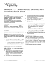
Figure 1E: Positioning for Maximum Brightness
NOTE: For maximum brightness, unit must be mounted
with flash angles as shown.
A0143-00
A0146-00
A0319-00
A0232-00
A0231-00
+
_
+
_
FROM FACP, MODULE
OR PREVIOUS DEVICE
FACTORY INSTALLED
SHORTING BAR
DIP
SWITCH
STROBE
+
HORN
+
STROBE
-
HORN
-
TO NEXT DEVICE
OR EOL

D900-22-00 4 I56-1453-012R
©2005 System Sensor
Strobe or Horn/Strobe with universal mounting plate:
1. Mount adapter plate to back box with screws B.
2. Complete field wiring.
3. Secure unit to plate with screws A.
Strobe or Horn/Strobe surface mount:
1. Mount adapter plate
and back box skirt to
back box with screws B.
2. Complete
field wiring.
3. Secure unit to
skirt with screws A.
Mounting Diagrams:
The horn and/or strobe will not work without power. The horn/strobe gets its
power from the fire/security panel monitoring the alarm system. If power is cut off for
any reason, the horn/strobe will not provide the desired audio or visual warning.
The horn may not be heard. The loudness of the horn meets (or exceeds) current
Underwriters Laboratories’ standards. However, the horn may not alert a sound
sleeper or one who has recently used drugs or has been drinking alcoholic beverages.
The horn may not be heard if it is placed on a different floor from the person in hazard
or if placed too far away to be heard over the ambient noise such as traffic, air condi
-
tioners, machinery or music appliances that may prevent alert persons from hearing
the alarm. The horn may not be heard by persons who are hearing impaired.
NOTE: Strobes must be powered continuously for horn operation.
The signal strobe may not be seen. The electronic visual warning signal uses an
extremely reliable xenon flash tube. It flashes at least once every second. The strobe
must not be installed in direct sunlight or areas of high light intensity (over 60 foot
candles) where the visual flash might be disregarded or not seen. The strobe may
not be seen by the visually impaired.
The signal strobe may cause seizures. Individuals who have positive photoic
response to visual stimuli with seizures, such as persons with epilepsy, should avoid
prolonged exposure to environments in which strobe signals, including this strobe,
are activated.
The signal strobe cannot operate from coded power supplies. Coded power
supplies produce interrupted power. The strobe must have an uninterrupted source
of power in order to operate correctly. System Sensor recommends that the horn and
signal strobe always be used in combination so that the risks from any of the above
limitations are minimized.
WARNING
The Limitations of Ceiling Mount Horn/Strobes
Three-Year Limited Warranty
System Sensor warrants its enclosed horn. strobe, or horn/strobe to be free from
defects in materials and workmanship under normal use and service for a period
of three years from date of manufacture. System Sensor makes no other express
warranty for this horn, strobe, or horn/strobe. No agent, representative, dealer, or
employee of the Company has the authority to increase or alter the obligations or
limitations of this Warranty. The Company’s obligation of this Warranty shall be
limited to the repair or replacement of any part of the horn, strobe, or horn/strobe
which is found to be defective in materials or workmanship under normal use and
service during the three year period commencing with the date of manufacture. After
phoning System Sensor’s toll free number 800-SENSOR2 (736-7672) for a Return
Authorization number, send defective units postage prepaid to: System Sensor,
Returns Department, RA #__________, 3825 Ohio Avenue, St. Charles, IL 60174.
Please include a note describing the malfunction and suspected cause of failure. The
Company shall not be obligated to repair or replace units which are found to be de
-
fective because of damage, unreasonable use, modifications, or alterations occurring
after the date of manufacture. In no case shall the Company be liable for any conse
-
quential or incidental damages for breach of this or any other Warranty, expressed
or implied whatsoever, even if the loss or damage is caused by the Company’s neg
-
ligence or fault. Some states do not allow the exclusion or limitation of incidental or
consequential damages, so the above limitation or exclusion may not apply to you.
This Warranty gives you specific legal rights, and you may also have other rights
which vary from state to state.
A
B
Screw types used for mounting:
A = #8 plastite
B = 8-32 ×
3
/4 pan head
A
B
4×4×1
1
⁄2
BBSCW (white)
BBSC (red)
FCC Statement
NOTE: This equipment has been tested and found to comply with the limits for a Class A digital
device, pursuant to part 15 of the FCC Rules. These limits are designed to provide reasonable pro
-
tection against harmful interference when the equipment is operated in a commercial environment.
This equipment generates, uses, and can radiate radio frequency energy and, if not installed and
used in accordance with the instruction manual, may cause harmful interference to radio commu
-
nications. Operation of this equipment in a residential area is likely to cause harmful interference
in which case the user will be required to correct the interference at his own expense.
A0317-00
A0318-00
Please refer to insert for the Limitations of Fire Alarm Systems
/