
P/N P-047550-1786-EN • REV 07 • ISS 08OCT15 1 / 2
Electronic Horn/Strobe Signal
Appliance Installation Sheet
Description
The horn/strobes are high quality signals intended for use in cUL
general signaling applications. The strobes flash at 1 fps across their
full operating voltage range. See Table 1 for model numbers and
“Specifications” for details.
Table 1: Models
Number
Description
8
67STR(*)-** Horn/Strobe, Surface Mount Indoor, Gray
868STR(*)
-** Horn/Strobe, Surface Mount Outdoor, Gray
869STR(*)
-** Horn/Strobe, Flush or Panel Mount Indoor, Gray
*
Insert lens color: C = Clear, R = Red, G = Green, B = Blue,
A
= Amber.
**
The horns are available in two voltages. Insert suffix as required:
N5 = 120 VAC, AQ = 24 V AC/DC
Installation
Install and wire this device in accordance with applicable national and
local codes, ordinances, and regulations, and in a manner acceptable
to the local authority having jurisdiction.
WARNINGS
• To reduce the risk of shock, do not connect AC or battery power to
the horn until directed in these instructions.
• To reduce the risk of shock, do not tamper with this device when
the signal circuit is energized. Disconnect all power and wait 5
minutes for stored energy to dissipate before handling.
1. Select a mounting method as detailed in Figure 1 and install the
electrical box using suitable hardware.
For outdoor applications, install the weatherproof box using four
#10 × 1-1/4 (32 mm) screws and caplugs provided in the enclosed
parts bag. Carefully adhere the gasket, part number
P-007549-0082 (provided in the enclosed parts bag) to the box as
shown in Figure 1.
Notes
• Be sure that the hook flange is facing outward as shown in
Figure 1 (item 10).
• The designation "TOP" on boxes denotes orientation of box
after installation.
2. Attach the mounting plate using two #8-32 screws provided with
the surface box or four #8-32 screws provided with weatherproof
box. The flush box uses two #8-32 screws (not provided).
3. Bring the signaling circuit field wiring into the electrical box.
4. Connect signaling circuit field wires to terminals on horn/strobe
assembly (Figure 2 through Figure 4).
5. Ground in accordance with national and local electrical codes. A
green ground screw is provided with both the indoor and outdoor
surface boxes.
6. Mount the horn/strobe on the mounting plate (Figure 1).
a. The inside of the top of the grille has hinges that pass through
cutouts and engage with tabs on the mounting plate. With the
bottom of the grille lifted out slightly, place the grille over the
mounting plate so that the hinges of the grille are in the
mounting cutouts.
b. Properly seat the grille by pressing the bottom in.
c. Fasten the bottom of the grille to the mounting plate by
installing the captive combination drive screw.
7. Apply power and activate the horn/strobe unit to verify that it is
operating properly.
Maintenance
Caution: Should the unit fail to operate properly, do not attempt repair.
Contact the supplier for replacement.
Perform a visual inspection and an operational test twice a year.
Specifications
N5 model AQ model
Operating voltage*
120 VAC
50/60 Hz
24 VAC
50/60 Hz
24 VDC
Operating current
, horn** 33 mA 72 mA 22 mA
Operating current
, strobe** 115 mA 390 mA 390 mA
Flash rate (per second)
Approximately 1 fps
Sound level output at
10 ft.
(3.05 m)
anechoic chamber
90 dBA nominal
Operating environment
Indoor: 93% at 90°F (32°C) relative
humidity; 32 to 120°F (0 to 49°C)
variable ambient temperature
Outdoor: 98% at 104°F (40°C) relative
humidity; −31 to 150°F (−35°F to
66°C) variable ambient temperature
* The operating voltage to the horn may be continuous or coded
such as march time or a temporal pattern meeting ISO8201
(ANSI S3.41) Audible Emergency Evacuation Signal.
** Horn and strobe currents are additive when connected in parallel.
Models 867STR(*)-AQ, 868STR(*)-AQ and 869STR(*)-AQ potentially
generate timing signals or pulses above 9 kHz and therefore have
been tested and found to comply with the limits for a Class A digital
device, pursuant to Part 15 of the FCC Rules. These limits are
designed to provide reasonable protection against harmful interference
when the equipment is operated in a commercial environment. This
equipment generates, uses and can radiate radio frequency energy
and, if not installed and used in accordance with the instruction
manual, may cause harmful interference to radio communications.
Operation of this equipment in a residential area is likely to cause
harmful interference in which case the user will be required to correct
the interference at his own expense.
Caution: Changes or modifications to this equipment not expressly
approved by the party responsible for compliance could void the user's
authority to operate the equipment.

2 / 2 P/N P-047550-1786-EN • REV 07 • ISS 08OCT15
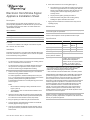
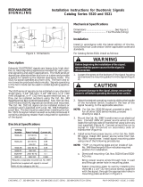
Figure 1: Detailed view
(1) Surface (outdoor)
(
2) Weatherproof box
(
3) Gasket
(
4) Flush/Panel
(
5) Standard North American 4 in. sq. × 1-1/2 in. deep electrical box
(Universal #52171) with 1-1/2 in. (38 mm) deep extension ring
(Universal #53151 or equivalent)
(
6) CAUTION CANADA: If using Iberville (Commander) extension
ring, use standard North American box with 2-1/8 in. (54 mm)
deep extension ring (Universal #53171)
(7) Surface (indoor)
(
8) Knockouts for 1/2 in. (13 mm) or 3/4 in. (19 mm) conduit; top,
bottom, back
(
9) Surface box
(
10) Hook flange
(
11) Mounting plate (supplied)
(
12) Electronic horn/strobe
(
13) Captive combination drive screw
(
14) Terminal block (see Figure 4)
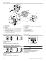
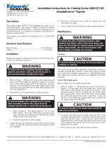
Figure 2: Wiring the horn and strobe on the same circuit
(1) Applicable voltage source
(2) Horn
(3) Strobe
(4) Polarity must be observed for units operating on VDC
Figure 3: Wiring the horn and strobe on different circuits
(1) Applicable voltage source
(2) Horn
(3) Strobe
(4) Polarity must be observed for units operating on VDC
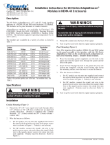
Figure 4: Terminals
Regulatory information
Ratings
CAN/CSA C22.2 No. 205
UL 464
Contact information
For contact information, see www.edwardsfiresafety.com
© 2015 Walter Kidde Portable Equipment, Inc.
All rights reserved.
(1)
(5)(4)
(3)
(2)
(6)
(10)
(9)
(8)
(7)
(14)(13)
(11)
5-59/64 in.
(150 mm)
3-13/32 in.
(87 mm)
3-5/16 in.
(84 mm)
5-5/8 in.
(143 mm)
#8-32
5/8 in.
(16 mm)
5-1/2 in.
(140 mm)
5-1/2 in.
(140 mm)
3 in. (76 mm) or
3-5/8 in. (92 mm)
(12)
(1)
(2) (3)
(4)
(1) (2) (3) (4)
-
 1
1
-
 2
2


Edwards Signaling 867STR Series Installation guide
- Type
- Installation guide
- This manual is also suitable for
Ask a question and I''ll find the answer in the document
Finding information in a document is now easier with AI
Related papers
-
 Edwards Signaling 869dstr-g1 Installation guide
-
 Edwards Signaling 90, 92 and 95 Series Installation guide
-
 Edwards Signaling AdaptaBeacon 94DDV2 G1 Series Installation guide
-
 Edwards Signaling 5520 series Installation guide
-
 Edwards Signaling 94DV2 Series Installation guide
-
 Edwards Signaling 94DV2 Series Installation guide
-
 Edwards Signaling 104 Series Installation guide


Other documents
-
EDWARDS 2447T Integrity Temporal Horn Installation guide
-
-
-
-
System Sensor SAA: MP120K User manual
-
-
Cooper Wheelock MTWP-24MCCH Installation Instructions Manual
-
-
-
Wheelock MT-24-WM User manual