Page is loading ...

D600-01-00 1 I56-1569-003R
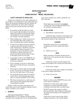
SpectrAlert Dual Strobe
For use with the following 24-volt models:
DS2475WAR DS2475RAR
DS2475_ _ _
Right Side Lens Color
Left Side Lens Color
Housing Color: “W” for White, “R” for Red
Lens colors: “A” for Amber and “R” for Red
INSTALLATION AND MAINTENANCE INSTRUCTIONS
3825 Ohio Avenue, St. Charles, Illinois 60174
1-800-SENSOR2, FAX: 630-377-6495
www.systemsensor.com
General Description
The SpectrAlert series notification appliances are designed to meet the
requirements of NFPA, The National Fire Alarm Code, and UL. Also, check
with your local Authority Having Jurisdiction for other codes or standards
that may apply.
This SpectrAlert DS2475 Strobe can be installed in systems using 24-volt
panels having DC or full-wave rectified (FWR) power supplies. The mod-
els can also be installed in systems requiring synchronization (module
MDL required) or systems that do not require synchronization (no module
required).
NOTICE: This manual shall be left with the owner/user of this equipment.
Power Supply Considerations
Panels typically supply DC filtered voltage or FWR (full-wave rectified)
voltage. The system design engineer must calculate the number of units
used in a zone based on the type of panel supply. Be certain the sum of
all the device currents do not exceed the current capability of the panel.
Calculations are based on using the device current found in the subsequent
charts and must be the current specified for the type of panel power sup-
ply used.
Wire Sizes
The designer must be sure that the last device on the circuit has sufficient
voltage to operate the device within its rated voltage. When calculating
the voltage available to the last device, it is necessary to consider the volt-
age drop due to the resistance of the wire. The thicker the wire, the less
the voltage drop. Generally, for purposes of determining the wire size nec-
essary for the system, it is best to consider all of the devices as “lumped”
on the end of the supply circuit (simulates “worst case”).
Typical wire size resistance:
18 AWG solid: Approximately 8 ohms/1,000 ft.
16 AWG solid: Approximately 5 ohms/1,000 ft.
14 AWG solid: Approximately 3 ohms/1,000 ft.
12 AWG solid: Approximately 2 ohms/1,000 ft.
Example: Assume you have 10 devices on a zone and each requires 50
mA average and 2000 Ft. of 14 AWG wiring (total length=outgoing
+return). The voltage at the end of the loop is 0.050 amps per device x
10 devices x 3 ohms/1,000 ft. x 2000 ft =3 volts drop.
Specifications
Voltage Range: 20 to 30 Volts DC or Full-Wave Rectified
with module: 21 to 30 Volts DC or Full-Wave Rectified
Flash Rate: 1 Flash Per Second
Operating Temperature: 32° F to 120° F (0° C to 49° C)
Light Output: 75 candela
Listings: UL S3593 (Strobe)
The same number of devices using 12 AWG wire will produce only 2 volts
drop. The same devices using 18 AWG wire will produce 8 volts drop.
Consult your panel manufacturer’s specifications, as well as SpectrAlert’s
operating voltage range to determine acceptable voltage drop
.
Note: If class “A” wiring is installed, the wire length may be up to 4 times
the single wire length in this calculation.
U.S. Patent Nos. 5,593,569;
5,850,178; 5,598,139; 6,049,446
Current Draws Per Strobe
DC FWR DC FWR DC FWR
169 220 140 191 115 174
AVERAGE CURRENT (mA)
24V Models
20V 24V 30V
DC FWR DC FWR DC FWR
460 560 450 570 420 620
PEAK CURRENT (mA)
24V Models
20V 24V 30V
DC FWR DC FWR DC FWR
190 230 220 290 290 370
IN RUSH CURRENT (mA)
24V Models
20V 24V 30V
Figure 1A. Powered by a 2-wire circuit:
System Operation: Non-Synchronized Devices
POWER
SUPPLY
TO NEXT
DEVICE
OR EOL
NOTE: Reversing polarity from power supply will stop powering one
strobe and start powering the other.
Figure 1B: Strobes
powered in tandem:
NOTE: Supply power must be
continuous for proper operation.
FACTORY
INSTALLED
WIRES
TO NEXT
DEVICE OR EOL
FACP

(+)
(—)
(+)
(—)
(+)
(—)
LEFT STROBE
POWER SUPPLY
(+)
(—)
(+)
(—)
(+)
(—)
RIGHT STROBE
POWER SUPPLY
TO NEXT
DEVICE
OR EOL
TO NEXT
DEVICE
OR EOL
D600-01-00 2 I56-1569-003R
The strobe will not work without power. The strobe gets its power from the fire/security panel
monitoring the alarm system. If power is cut off for any reason, the strobe will not provide the
desired visual warning.
NOTE: Strobes must be powered continuously for horn operation.
The signal strobe may not be seen. The electronic visual warning signal uses an extremely reliable
xenon flash tube. It flashes at least once every second. The strobe must not be installed in direct
sunlight or areas of high light intensity (over 60 foot candles) where the visual flash might be dis-
regarded or not seen. The strobe may not be seen by the visually impaired.
The signal strobe may cause seizures. Individuals who have positive photic response to visual
stimuli with seizures, such as persons with epilepsy, should avoid prolonged exposure to environ-
ments in which strobe signals, including this strobe, are activated.
The signal strobe cannot operate from coded power supplies. Coded power supplies produce
interrupted power. The strobe must have an uninterrupted source of power in order to operate cor-
rectly. System Sensor recommends that the horn and signal strobe always be used in combination
so that the risks from any of the above limitations are minimized.
The Limitations of Strobes
WARNING
Figure 2. Powered by a 4-wire circuit to provide independent left
strobe and right strobe operation (Remove factory installed
jumpers, see Figure 1B):
NOTE: Strobes must be powered continuously for proper operation.
Figure 3: Synchronizing strobes using MDL:
Three-Year Limited Warranty
System Sensor warrants its enclosed strobe or strobe to be free from defects in materials and work-
manship under normal use and service for a period of three years from date of manufacture.
System Sensor makes no other express warranty for this strobe. No agent, representative, dealer,
or employee of the Company has the authority to increase or alter the obligations or limitations of
this Warranty. The Company’s obligation of this Warranty shall be limited to the repair or replace-
ment of any part of the strobe which is found to be defective in materials or workmanship under
normal use and service during the three year period commencing with the date of manufacture.
After phoning System Sensor’s toll free number 800-SENSOR2 (736-7672) for a Return
Authorization number, send defective units postage prepaid to: System Sensor, Returns
Department, RA #__________, 3825 Ohio Avenue, St. Charles, IL 60174. Please include a note
describing the malfunction and suspected cause of failure. The Company shall not be obligated to
repair or replace units which are found to be defective because of damage, unreasonable use, mod-
ifications, or alterations occurring after the date of manufacture. In no case shall the Company be
liable for any consequential or incidental damages for breach of this or any other Warranty,
expressed or implied whatsoever, even if the loss or damage is caused by the Company’s negli-
gence or fault. Some states do not allow the exclusion or limitation of incidental or consequential
damages, so the above limitation or exclusion may not apply to you. This Warranty gives you spe-
cific legal rights, and you may also have other rights which vary from state to state.
Mounting
If you would prefer to switch the lens colors, the strobe modules are field-
reversible. (Fig. 4)
To reverse the strobe module: insert screwdriver, as shown in Fig. 4, to
unlock snap. While pushing in the screwdriver, pull back on the strobe
module. Hinge the strobe module, disengage the Locking Rib, and lift the
module away from the mounting plate. Turn the module so that it is
upside down from its original position, re-insert the module into the
mounting plate (be sure to insert the Locking Rib into the slot), and press
the module into the mounting plate. The strobe module will make a
“click” when it has locked into place. Turn entire assembly so that the
lenses are on the bottom. The unit can now be mounted.
The unit can be mounted to a single-gang back box, or to a 4″ x 4″ back
box, using the mud ring provided.
1. Complete field wiring.
2. Align dual strobe over back box
and secure with screws.
2-INCH BACK BOX
#6-32
PAN HEAD
SCREWS
INSERT SCREWDRIVER INSERT SCREWDRIVER
POWER
SUPPLY
MDL
RED
STROBES
POWER
SUPPLY
MDL
AMBER
STROBES
TO NEXT
DEVICE
OR EOL
TO NEXT
DEVICE
OR EOL
Please refer to insert for the Limitations of Fire Alarm Systems
INSERT SCREWDRIVER INSERT SCREWDRIVER
LOCKING RIB
INSERT SCREWDRIVER
TO REMOVE
Figure 4: Reversing the strobe module:
FCC Statement
NOTE: This equipment has been tested and found to comply with the limits for a Class A digital
device, pursuant to part 15 of the FCC Rules. These limits are designed to provide reasonable pro-
tection against harmful interference when the equipment is operated in a commercial environment.
This equipment generates, uses, and can radiate radio frequency energy and, if not installed and
used in accordance with the instruction manual, may cause harmful interference to radio commu-
nications. Operation of this equipment in a residential area is likely to cause harmful interference
in which case the user will be required to correct the interference at his own expense.
/