215U-2 wireless mesh networking I/O and gateway
installation guide
HAZLOC NOTICES
The 215U-2 is suitable for use in
hazardous locations that are rated Class
I Division 2, Groups A, B, C, D.
The 215U-2 must be installed in an
enclosure that maintains an ingress
protection rating of IP54 and meets the
enclosure requirements of EN50014 or
EN60079-0.
The RF coaxial cable must be installed
in a metallic conduit, per the US
National Electrical Code (NEC) or NFPA.
SUP+ and SUP- terminals must only be
powered from an NEC Class 2 circuit.
WARNING - EXPLOSION
HAZARD
Do not disconnect equipment while the
circuit is live unless the area is known
to be free of ignitable concentrations.
Substitution of any component may
impair suitability for Class I Division 2.
NOTE
The 215U-2 module ships from
the factory configured for global
frequency and power. Set the radio
region to access country specific
radio options.
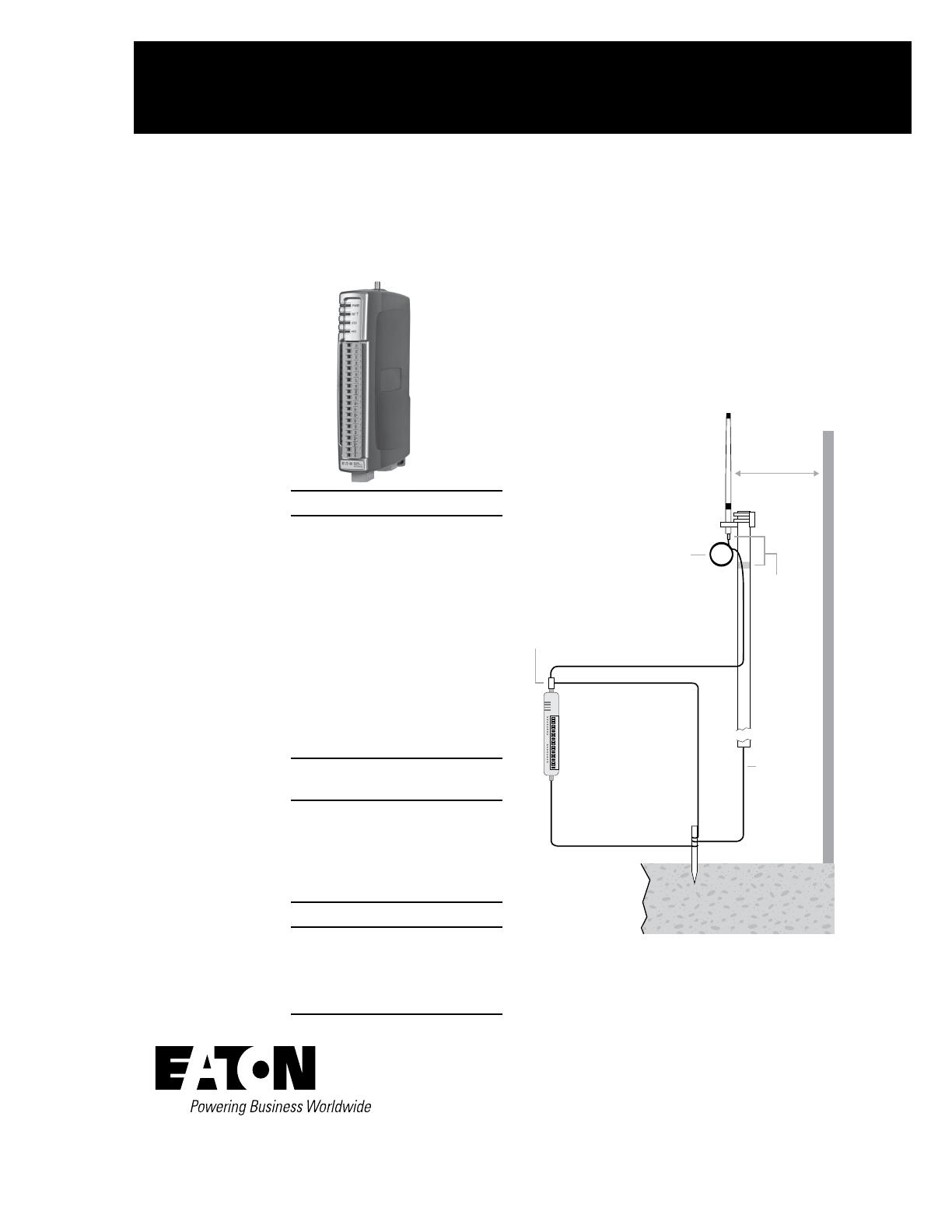
Antenna installation
When selecting an antenna, consider radio proximity.
Use Figure 1 as a guide for installing an antenna and attaching it
to the 215U-2.
Note: Do not operate the radio without an antenna or RF load
fitted
Figure 1. Antenna installation
Earth Stake
For maximum
range, install
above local
obstructions.
Earth Conductor
at least 5 AWG
(16 mm
2
)
*
Wavelength:
2.4GHz = 5" (12.5cm)
Weatherproof
Connections
(recommended:
3M
™
23 self-
bonding tape)
Mast
Coaxial Cable
GND
at least 11 AWG (4 mm
2
)
Stress
Relief
Loop
Antenna
*
GND
Surge Arrestor
(recommended)
215U-2
Provide good ground
connection to mast,
module, and surge
arrestor.
If ground conditions
are poor, use more
than one stake.
1 Wavelength
(minimum)
Connecting to the module for configuration
USB:
•
USB Driver “.inf”file is available from Eaton Website
•
Connect to the device at 192.168.111.1
•
The PC will be automatically assigned an IP address via DHCP
Ethernet:
•
Connect to the device at the IP address on the module label
•
Assign the PC a static IP address on the 192.168.0/24 subnet
Username: user
Password: user
Instruction Leaflet IL032051EN
Effective March 2017


