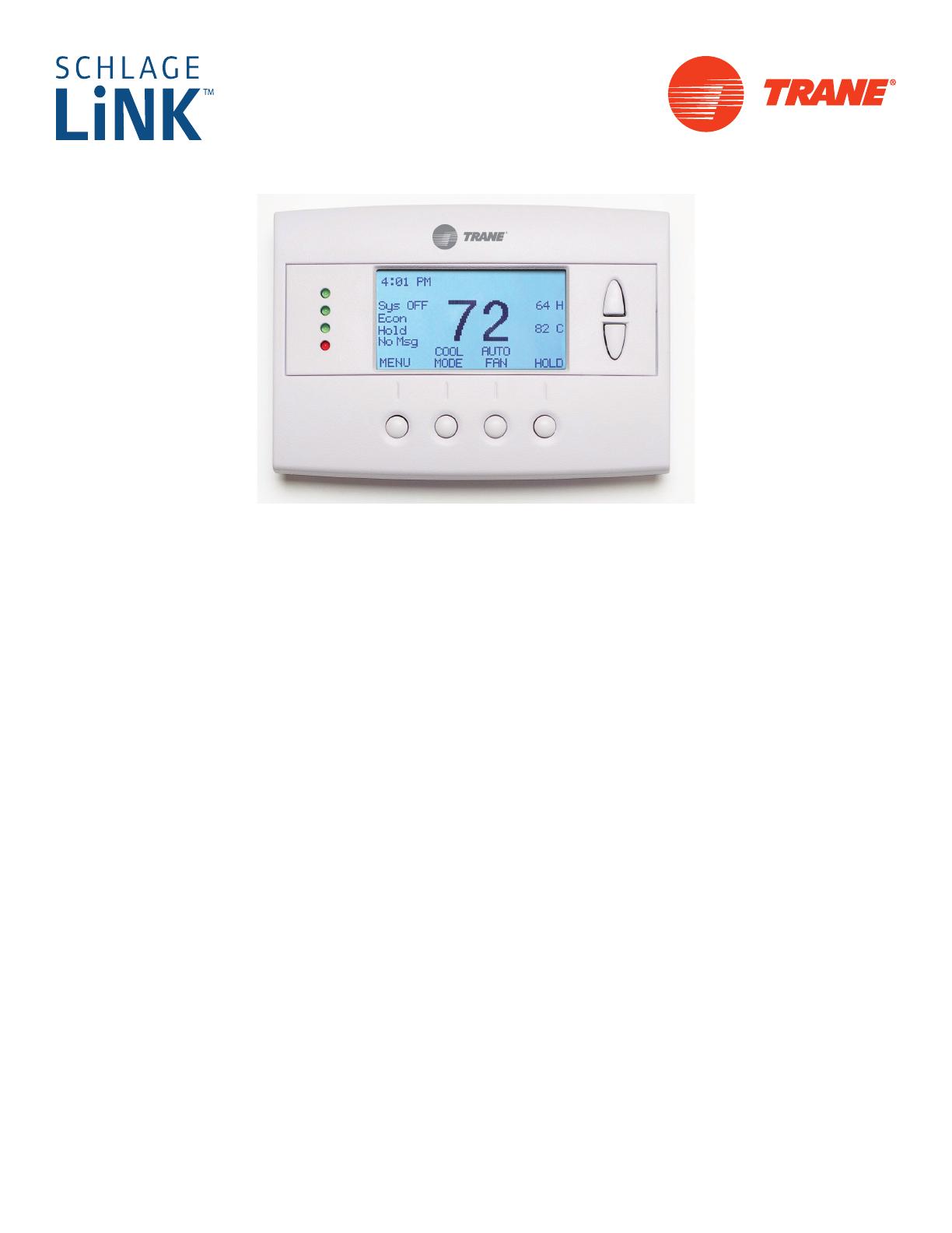
Vizio Z WAVE TZEMT400AB32MAA User manual

Category
Thermostats
Type
User manual

This manual is also suitable for

Thermostat
Model TZEMT400AB32MAA
User Guide
Contents
Product Specifications ............................................2
Overview ...................................................................3
Z-Wave™ Thermostat ................................................ 3
Display operation ........................................................ 3
Z-Wave™ Operation and Programming ................. 4
Inclusion ...................................................................... 4
Exclusion ..................................................................... 4
Inclusion and Exclusion .............................................. 4
Operation ..................................................................5
Thermostat Control Buttons ........................................ 5
LEDs ........................................................................... 5
Thermostat Screens .................................................... 5
Thermostat Control Screen ......................................... 5
Minimized Thermostat Screen ................................... 5
Menu Selection Screen ............................................... 5
Schedules Screen ...................................................... 5
User Settings Screen .................................................. 6
Usage Graph ............................................................... 6
ESM Setpoints ............................................................ 6
ZWave Install ............................................................... 6
Thermostat Info Screen .............................................. 6
Thermostat Control Screen ....................................7
Temperature Display ................................................... 7
Setpoint Display .......................................................... 7
Clock Display .............................................................. 7
Thermostat Control Screen Buttons ........................... 8
MENU Button ............................................................. 9
MODE Button ............................................................ 10
FAN Button ................................................................ 11
RUN/HOLD/ESM Button ........................................... 11
LED Displays ............................................................. 12
Main Menu ..............................................................13
Schedules ................................................................. 14
Heat and Cool Schedules ......................................... 15
Copy Schedule .......................................................... 16
User Settings ............................................................ 17
Set Clock ................................................................... 18
Filter Service ............................................................. 19
Maint Service ............................................................ 20
Sensor Calibration..................................................... 21
Backlite/Display ......................................................... 22
Thermostat Info ........................................................ 23
Installer Settings Menu (Hidden Screen) ................ 24
Installer Settings Summary ....................................... 26
HVAC System Connection ....................................28
HVAC System Compatibility ...................................... 28
Remote Communications .......................................... 28
Standard Gas/Electric HVAC System Wiring ............ 29
Heat Pump HVAC System Wiring ............................. 30
HVAC System Operation and Setup .....................31
General Heating and Cooling Operation ................... 31
Standard HVAC System Types ................................ 31
Setup ......................................................................... 31
Heat Pump HVAC System Types ............................. 31
Setup ......................................................................... 32
Installation ..............................................................33
Power ........................................................................ 33
Warranty .................................................................34
2
Product Specifications
Product Model: TZEMT400AB32MAA
Product: Thermostat for Heating and Cooling HVAC System control.
Z-Wave™ RF communications enabled
Thermostat
Size: 5.7” wide x 4.0” height x 1.2” depth
Display: Graphical LCD, 2.75” x 1.5”, 64x128-pixel
Backlight: Yes, Blue/white, Controllable, on, off, timeout
Contrast: Adjustable on screen
Buttons: 6
LEDs: 4 (3 green, 1 red)
Power: 24VAC from HVAC System
HVAC System Type Compatible: Standard (gas/electric) or Heat Pump
Multistage System Compatible: Standard HVAC Systems: 2 stage heating, 2-stage cooling
Heat Pump Systems: 3 stage heating (2-compressor, 1 aux heat), 2-stage cooling
Heat Pump change over valve: Selectable change over with cool or with heat
Communications: Z-Wave™ RF
3
Overview
Z-Wave™ Thermostat
The Z-Wave™ thermostat provides for typical thermostat control of a central heating and cooling HVAC system plus has
the added feature of Z-Wave™ communications for remote control.
The thermostat has a large, backlit graphical display, control buttons, status LEDs and a temperature sensor. The
thermostat can display multiple screens for different functions of the thermostat. In the default thermostat control screen,
shown below, it displays the current temperature, setpoint, system mode, manual fan mode, time, outside temperature and
other information.
72
MODE
FAN
MENU
77 H
Sys Off
Run
Filter
RUN
74 C
Status
Indicator
LEDs
Setpoint
Up/Down
Buttons
Function Control Buttons
Heat (H)
And
Cool (C)
Setpoints
On-screen
dynamic labels
Display operation
Thermostat control screen
Normally the thermostat displays the thermostat control screen as shown above. Using the Menu button, you can access
other screens and functions of the thermostat.
Minimized Display Mode
Optionally, you can set the thermostat to show only the temperature in a minimized display mode.
This mode can be set on or off in the thermostat Users Settings screen if enabled. (See page 16 for more information)
Other screens
Other standard screens are selected by the Menu button and include: Schedules, User Settings, Usage Graph, ESM
Setpoints and Thermostat Info. Other screens, such as the Schedules screen, may be present and selectable from the
menu button depending on options included or selected in the installation setup process.
Backlight
The thermostat has a backlit display for low light and night visibility. It can be set to remain on constantly, or to turn off
after a 20-45 second delay. These are selectable in the User Settings menu.
4
Z-Wave™ Operation and Programming
Z-Wave™ controllers from various manufacturers may support the Z-Wave™ Thermostat General V2 Device class used
by the Trane Z-Wave™ Thermostat. The following procedure will allow the thermostat to be added to a Z-Wave™ network.
If you are using a controller that is not a Schlage bridge, consult the instructions that came with the controller to find out
how to enroll a new device.
Inclusion
Hold the bridge within 6 feet (1.8 meters) of the thermostat throughout all of step 2.a.
Note: After you begin the enrollment process, you have 30 seconds to complete the remainder of the
steps. Study the steps below before beginning.
Press and release the plus (+) button on the bridge.b.
Press the c. MENU button on the thermostat.
Scroll down to d. Z-Wave Install, and press the Select button.
Press the e. Yes button to enroll the thermostat.
Observe the lights on the bridge. The orange light will blink while enrollment is taking place. Enrollment is f.
complete when the orange light becomes solid.
Exclusion
Hold the bridge within 6 feet (1.8 meters) of the thermostat throughout all of step 2.a.
Note: After you begin the enrollment process, you have 30 seconds to complete the remainder of the
steps. Study the steps below before beginning.
Press and release the minus (-) button on the bridge.b.
Press the c. MENU button on the thermostat.
Scroll down to d. Z-Wave Install, and press the Select button.
Press the e. Yes button to exclude the thermostat.
Observe the lights on the bridge. The orange light will blink while exclusion is taking place. Exclusion is f.
complete when the orange light becomes solid.
Inclusion and Exclusion
Inclusion or exclusion is started by putting the controller into add node or remove node state and performing the procedure
outlined above. As part of the process, the thermostat sends a node information frame at normal power. Low power
inclusion or low power exclusion is not possible.
5
Operation
Thermostat Control Buttons
The Thermostats buttons are “Soft Keys” meaning that they change functions when you change screens. The function of
the button is defined by “on-screen labels” that are dynamic and change when you change screens.
LEDs
The Thermostat has four LED’s that displays status information. The LEDs have dynamic “on-screen” labels that can
change with the screen being displayed.
Thermostat Screens
A unique feature of the Thermostat graphical display is the ability to have multiple display screens. In addition to a main
thermostat control screen, menus and other control screens for special functions are provided. This makes an intuitive
and easy to use “user interface”. It allows the many functions of the Thermostat to be easily navigated.
The main screen is the Thermostat Control Screen. From this screen you can access a menu screen that will list other
control screens or setup screens.
Thermostat Control Screen
This is the thermostats default screen and the only screen needed for basic thermostat operation (temperature setting
and heat/cool mode selection). All other screens will automatically timeout and return this screen after 120 seconds of no
activity.
Minimized Thermostat Screen
(This feature is disabled by default. See page 16, Screen Timeout for more information)
The main thermostat screen will go to a “minimized” screen after a 30 second timeout period. This presents a simple
uncluttered display of the current room temperature.
Menu Selection Screen
Pressing the Menu button on the Thermostat Control Screen will go to the Menu Selection screen. This screen presents a
list of the other functions or setup screens that can be selected.
Schedules Screen
(Optional screen) Only shows up in the Menu Selection list if local scheduling is enabled. (See Installer Settings, then
System Settings Menu and then Schedule Enable on page 23).
This screen is used to view and edit the time based setback schedules for the thermostat.
Thermostat User Guide
6
User Settings Screen
This screen is a submenu of user settings for the initial setup of the thermostat. You can set the clock, minimized screen
timeout, Fahrenheit or Centigrade selection, sensor calibration and display settings.
Usage Graph
Shows daily heating and cooling runtime hours for a week.
ESM Setpoints
This screen is a submenu of the Energy Savings Mode settings. You can set the heating and cooling setpoint setback
temperatures. These settings are used when the thermostat is in the ESM mode.
ZWave Install
This screen is a submenu for installing the thermostat into a Z-Wave network. When the Z-Wave network controller is
ready to install the thermostat, press the YES button to install.
Thermostat Info Screen
This is a quick reference list of the thermostat firmware versions, Z-Wave network addresses and HVAC system setup.
7
Thermostat Control Screen
72
MODE
FAN
MENU
77 H
Sys Off
Run
Filter
10:25 AM
RUN
74 C
The main Thermostat Control Screen is the default display screen and is the screen that is normally displayed on the
Thermostat.
Temperature Display
The Thermostat will display the current temperature from the internal temperature sensor.
Setpoint Display
The heating and cooling setpoints are displayed next to the Setpoint Up/Down buttons. In the HEAT mode, the Up/Down
buttons change the heat setpoint. In the COOL mode, they change the cooling setpoint. When in AUTO mode, the buttons
change the last call’s heating or cooling setpoint. Note that the setpoints will “push” each other if they are adjusted to get
within the minimum Heat/Cool separation setting. This is normally 3 degrees.
Clock Display
The current time is displayed in the upper left corner of the main screen. Set the clock from the User Settings Menu.
The time will blink when the clock has not been set.
Thermostat User Guide
12
Thermostat Control Screen Buttons
Setpoint Up and Down Buttons
Pressing the Up or Down button in the main Thermostat Control Screen will take you to the Heating Setpoint or Cooling
Setpoint screen, as shown below.
72
Done
HEATING SETPOINT
Heating
and
Cooling
Setpoint
setting
buttons
Up
Down
The UP and DOWN buttons adjust the setpoint temperature. Pressing the UP button will increment the setpoint value by
one degree and conversely, pressing the Down button will decrement the setpoint one degree. Pressing and holding a
button down will cause the setpoint to continuously change until the button is released.
Setpoint Range: The setpoints can be set from 55°F to 90°F (12°C to 32°C) for Heating or 60°F to 99°F (15°C to 37°C)
for Cooling.
Setpoint Push: Note that you cannot lower the cooling setpoint below the heating setpoint. The thermostat will push
the heating setpoint lower if you try to lower the cooling below the heating setpoint. It maintains a 3 degree separation
between the heating and cooling setpoint. The same is true for raising the heating setpoint above the cooling setpoint.
Again the thermostat will “push” the cooling setpoint up to maintain the 3 degree separation.
NOTE: If the system mode is OFF, pressing the setpoint Up or Down buttons will take you to the system mode
screen. You must set the mode to an operating mode before you can change the setpoints.
To change the Heat Setpoint you must be in Heat mode, to change the Cool Setpoint you must be in the Cool
mode.
If you are in Auto mode when you press the Up or Down buttons, you will go to the last call’s mode, heating or
cooling, setpoint setting screen.
MENU Button
12
MENU Button
The Menu button changes the screen display to the MAIN MENU screen which show what other functions are available on
the Thermostat. These are dynamic and can change with the version of the thermostat you have, but the standard ones
include:
Main Thermostat Screen
Menu Button
Menu Selection Screen
User Settings
Usage Graph
ESM Setpoints
ZWave Install
Thermostat Info
RUN
AUTO
FAN
OFF
MODE
MENU
Thermostat User Guide
12
MODE Button
The MODE button controls the HVAC system mode. The current mode selected is displayed above the button. Pressing
the MODE button will take you to the System Mode screen.
Pressing the Up or Down buttons will scroll through the mode options. Pressing done or waiting for the screen to timeout
will select the new mode.
System Mode Screen
OFF
HEATING
COOLING
AUTO
EHEAT
Done
SYSTEM MODE
Use the Up/Down
buttons to scroll
through the
Modes.
Mode
Mode Operation
Off Mode: System is off. No heating or cooling will come on. If system was on, it will turn off.
Heat Mode: Only heating will occur.
Cool Mode: Only cooling will occur.
Auto Mode: Heating or cooling will come on according to the heating and cooling setpoints. The system will automatically
switch between heating and cooling when the temperature exceeds the appropriate setpoints.
EHEAT Mode: Emergency Heat mode is only displayed when Heat Pump HVAC System Type is selected. During extreme
weather conditions or when there is a compressor failure with the heat pump system, setting the mode to EHEAT will
allow the supplemental heat to come on whenever there is a heat call to provide heating and also disables the compressor
outputs.
FAN Button
12
FAN Button
The FAN button controls the HVAC system’s MANUAL fan. The current manual fan mode is displayed above the button.
Pressing the FAN button will take you to the FAN MODE screen shown below.
Fan Mode Screen
AUTO
ON
CYCLE*
Done
FAN MODE
Use the Up/Down
buttons to scroll
through the
Modes.
FAN
Normally the FAN mode is in the Auto mode (the system fan is automatically controlled by HVAC system). If you want the
FAN on manually, select the ON mode. The fan will run continuously until it is turned to off by selecting AUTO mode.
NOTE: If the Fan Cycler feature is enabled in the Installer Setup, the additional fan mode “Cycle” will be available.
This mode cycles the fan on and off per the settings for fresh air ventilation.
RUN/HOLD/ESM Button
The RUN/HOLD/ESM button controls the automatic SCHEDULE operation. Pressing this button will take you to the
SCHEDULE MODE screen as shown below.
Run/Hold/ESM Screen
HOLD
RUN
ENERGY SAVING MODE
Done
SCHEDULE MODE
Use the Up/Down
buttons to scroll
through the
Modes.
RUN
Run Mode. In the run mode, the thermostat schedule is running and setpoints will change according the times and
temperatures in the schedule. The schedule can be local (if enabled in the Installer Settings) or remote via the Z-Wave
network.
Hold Mode. This holds the current temperature setpoint settings. The schedule operation is inhibited.
Energy Savings Mode (ESM). This is a setback mode. When selected, the ESM temperature setpoint settings are used.
It also inhibits schedule operation.
Thermostat User Guide
12
LED Displays
The Thermostat Control Screen has the following LED and on-screen labels numbered from top to bottom.
LED 1 Green: System Operation display•
Sys Off• displayed = HVAC system is OFF; LED Off.
WAIT• displayed = Minimum Off Time (MOT)delay is active; LED Off (Note: See pages 25 and 30 for more
information on the Minimum Off Timer)
Cool On• displayed = Cooling system is running; LED On.
Cool On• displayed = Cooling Min Run Time (MRT); LED On. (Note: See pages 25 and 30 for more information on
the Minimum Run Timer)
Heat On• displayed = Heating system is running; LED On.
Heat On• displayed = Heating Minimum Run Time (MRT); LED On. (Note: See pages 25 and 30 for more
information on the Minimum Run Timer)
LED 2 Green: System Stage display•
No display = 1st stage heating or cooling. LED Off.•
2nd Stg• displayed = Stage 2 heating or cooling is active. LED On.
Aux Heat• displayed = Stage 3 heating is active. LED On.
LED 3 Green: Run/Hold/ESM display. Shows state of Schedule Run/Hold Mode.•
Run• displayed = Schedule mode is active. LED Off.
Hold• displayed = Temperature hold is active. LED On.
ESM• displayed = (Energy Savings Mode) Temperature preset is active. LED On.
LED 4 RED: Alert LED. Used for other system alerts•
No display = No alerts or messages. LED Off.•
Filter• displayed = Filter run timer reached. LED On.
Maint• displayed = Maintenance run timer reached. LED On.
13
Main Menu
The Thermostat has a menu tree that can be accessed by pressing the “Menu” button on the Main Thermostat screen.
Various configurations of the Thermostat can have different screen contents. The first screen that will come up is the
Menu Selection screen. This is a list of the other menus or functions that can be accessed.
Schedules Screen. (Optional Screen) Only shows up in the Menu Selection list if scheduling is enabled. (See Installer
Settings, then System Settings Menu and then Schedule Enable on page 23). This screen is used to view and set the
programmable setback schedules of the thermostat.
User Settings Screen. This screen is used to set the Clock, Filter Service and Maintenance Service, Screen Timeout,
Fahrenheit/Celsius settings, Sensor Calibration and Backlite/Display settings.
Usage Graph. Shows daily heating and cooling run time hours for a week.
ESM Setpoints. Used to set the Energy Savings Modes heating and cooling setpoints.
ZWave Install. Used to install the thermostat into a ZWave network.
Thermostat Info Screen: This screen shows the firmware versions of the Thermostat and Zwave interface, HVAC system
type and equipment options.
Main Menu
Menu Selection
User Settings
Usage Graph
ESM Setpoints
ZWave Install
Don
e
Select
Screen navigation buttons:
Done
Return to Thermostat Screen
Not used
Not used
Select menu item at pointer
Select
Move menu selection pointer up
Move menu selection pointer
down
Thermostat User Guide
27
Schedules
Schedules is an optional menu item. It will only show up in the menu list if “Schedules” is enabled in the Installer settings
for the thermostat (See page 23). Provides for local schedule control. The Schedules Screen allows you to review and
set the setback schedule for the thermostat. The thermostat has a 4 x 7 schedule. Four times a day can be selected for
changes to the heating and cooling setpoints. Each day of the week can have a different schedule. Groups of days can
be copied with the same schedule. When the thermostat is set to “Run” mode, the schedule will be executed daily, with
the setpoints being changed as per that days schedule stored in the thermostat. “Hold” mode stops schedule operation
and holds the current setpoints until changed manually or by network commands.
The Schedules Screen gives you the option of setting a custom setback schedule or to load one of two preset schedules.
Menu Options
• HeatandCool:Youcanchangetheindividualday/hourandsetpointsfortheHeatingandCoolingscheduleby
selecting this menu item.
• Preset:Comfort:Thisisapresetschedulewithmildsetbacks.SelectthismenuitemtoloadtheComfort
schedule into the thermostat.
• Preset:EnergyStar:Thisisapresetschedulewithdeepersetbacks.SelectthismenuitemtoloadtheEnergy
Star schedule into the thermostat.
Schedules Screen
Select Schedule
Heat and Cool
Preset: Comfort
Preset: Energy Star
Don
e
Select
Screen navigation buttons:
Done
Select
Return to Main Menu Screen
Select the schedule to view or modify
Move menu selection pointer up
Move menu selection pointer
down
Heat and Cool Schedules
27
Heat and Cool Schedules
When you select the Heat and Cool Schedule menu item, the “day” Schedule programming screen opens and the
schedule for current day will be displayed. Use the scroll buttons to highlight the data to be modified. Once the data has
been highlighted, use the +/- buttons to change the value of the data.
To copy a days schedule to another day or group of days, move the cursor to “c” on the bottom right of the schedule
screen. When you highlight the “c”, the button below will become “Copy”. Press this button to change to the Copy
Schedule Screen.
Schedule Screen
Monday
Schedule
Time Heat Cool
Morn 6:00 A 72 82
Day 9:00 A 68 84
Eve 5:00 P 74 76
Nite 10:00 P 70 78
Don
e
Next
+
_
c
Screen navigation buttons:
Done
Next
Copy
Return to Main Menu Screen
Scroll Back
Scroll Forward
Select the next Day schedule
OR if the copy “c” is selected,
go to copy schedule screen.
+ Increment time or temperature
- Decrement time or temperature
Thermostat User Guide
27
Copy Schedule
The Copy Schedule screen is a sub screen of the Schedule screen. The Copy Schedule screen allows you to copy a day’s
schedule to another day or group of days.
First select the day to be copied in the Schedule screen. Scroll to the “c” at the bottom of the Schedule screen to highlight
it. The “Next” button will change to the “Copy” button. Press the “Copy” button to open the Copy Schedule screen.
Scroll through the days and select the days you want to copy the schedule to by setting the “N” under each day to “Y” by
using the Yes/No buttons.
After selecting all the days desired, press the “Copy” button.
Exit the Copy Schedule screen with the “Back” button.
Copy Schedule Screen
Copy Monday Schedule
to
Sun Tue Wed Thu Fri
Sat
N Y Y Y Y N
Bac
k
Copy
Yes
No
Screen navigation buttons:
Return to Schedule Screen
Move back with selection bar
Move forward with selection bar
Copy the schedule to the selected days
Back
Copy
Yes - Copy schedule to this day
No - Do not copy to this day
User Settings
27
User Settings
The User Settings screen allows you to set or change various user options of the thermostat such as the Clock, Minimized
Screen timeout, Fahrenheit/Celsius mode, Sensor Calibrations, and Display settings.
Menu options:
Set Clock: Select this menu item to go to the Clock setting screen.•
Filter Service: Sets/resets the filter timer/alert.•
Maint Service: Sets/resets the maintenance timer/alert.•
Screen Timeout: Select the Screen Timeout time in seconds. Options are 0 or 20 to 120 (default set to 0 seconds). •
This is the time before any screen reverts to the Minimized Screen (temperature display only), after you stop
pushing buttons. Minimized Screen feature is disabled by setting this time to “0”.
F/C Mode: Select which temperature display mode you desire, Fahrenheit (F) or Celsius (C).•
Sensor Calibration: Select this menu item to go to the Sensor Calibration screen. •
Backlite/Display: Select this menu item to go the Backlite/Display settings screen. This menu allows you to set the •
backlight timeout period and adjust the display contrast.
User Settings Screen
User Settings
Set Clock
Filter Service
Maint Service
Screen Timeout 0
Don
e
Select
+
_
Done
Select
Return to Main Menu
Increment value
Decrement value
Select the function to be set
+
_
Move menu selection pointer up
Move menu selection pointer
down
Thermostat User Guide
27
Set Clock
The Set Clock screen allows you to set the Thermostat’s internal clock.
To set the Time and Date, move the cursor with the navigation arrows until the data you want to change is highlighted.
Using the + and – buttons to increment or decrement the data to the desired setting.
When finished, press the SET button to return to the Main Menu screen or wait for screen to timeout.
NOTE: If the clock has been reset by an extended power outage, the Clock display on the thermostat screen will be
blinking. Pressing the MENU button will take you directly to this screen to set the clock.
Set Clock Screen
Set Clock
Time 12:00 PM
Date 7/13/08
Day Thu
Back
Set
+
_
Screen navigation buttons:
Cancel and return to User Settings Menu
Move back with selection box navigation arrow
Move forward with selection box navigation
arrow
Back
Set
+ Increment selected item
-
Decrement selected item
Filter Service
27
Filter Service
The Filter Service screen will show the accumulated Filter Runtime hours as well as the Service Interval that will be used
to trigger a Filter Message. Any type of HVAC operation that causes the HVAC system fan to run will cause the Filter
Runtime value to increase.
When the Runtime hours equals the Service Interval hours, the Red LED will flash along with a “Filter” message to remind
you to replace the filter. Pressing the Menu button will take you to the Filter Service screen. Once the filter has been
replaced, press the Reset button to reset the Filter Runtime value to zero.
The Service Interval period can be changed using the +/- buttons.
Filter Service Screen
Filter Service
Don
e
Reset
+
Filter Runtime
Service Interval
12 HRS
300 HRS
Screen navigation buttons:
Done
Reset
+
Return to Main Menu Screen
Increase the Service Interval by 1
hour
Decrease the Service Interval by 1
hour
Thermostat User Guide
27
Maint Service
The Maintenance Service screen will show the accumulated Heat and Cool Runtime hours as well as the Service Interval
that will be used to trigger a Maintenance Message. Any HEAT or COOL type of HVAC operation will cause the respective
Runtime values to increase.
When the combined HEAT and COOL Runtime hours equals the Service Interval hours, the Red LED will flash along with
a “Maint” message to remind you your HVAC system may require periodic maintenance. Pressing the Menu button will
take you to the Filter Service screen. The Reset button can be pressed and the HEAT and COOL Runtime values will be
reset to zero.
The Service Interval period can be changed using the +/- buttons.
Maintenance Service Screen
Maintenance Service
Don
e
Reset
+
Heat Runtime
Service Interval
0 HRS
3000 HRS
Cool Runtime
0 HRS
Runtim
e
Screen navigation buttons:
Done
Reset
+
Return to Main Menu Screen
Increase the Service Interval by 1
hour
Decrease the Service Interval by 1
hour
  • Page 1 1
  • Page 2 2
  • Page 3 3
  • Page 4 4
  • Page 5 5
  • Page 6 6
  • Page 7 7
  • Page 8 8
  • Page 9 9
  • Page 10 10
  • Page 11 11
  • Page 12 12
  • Page 13 13
  • Page 14 14
  • Page 15 15
  • Page 16 16
  • Page 17 17
  • Page 18 18
  • Page 19 19
  • Page 20 20
  • Page 21 21
  • Page 22 22
  • Page 23 23
  • Page 24 24
  • Page 25 25
  • Page 26 26
  • Page 27 27
  • Page 28 28
  • Page 29 29
  • Page 30 30
  • Page 31 31
  • Page 32 32
  • Page 33 33
  • Page 34 34

Vizio Z WAVE TZEMT400AB32MAA User manual

Category
Thermostats
Type
User manual
This manual is also suitable for

Ask a question and I''ll find the answer in the document

Finding information in a document is now easier with AI