Page is loading ...

20
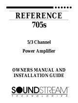
SERIES AND PARALLEL WIRING
2-4 ohm drivers in parallel
= 2 ohms
2-4 ohm drivers in series
= 8 ohms
4-4 ohm drivers in parallel
=1 ohm
SOUNDSTREAM TECHNOLOGIES
120 Blue Ravine Road Folsom California 95630 USA
ph 916.351.1288 fax 916.351.0414
rev B - 4.17.96
1
REFERENCE
Class A
5.0 & 10.0
Power Amplifiers
OWNERS MANUAL
AND
INSTALLATION GUIDE

2
CONGRATULATIONS!
You now own the REFERENCE Class A Amplifier, the product of an
uncompromising design and engineering philosophy. Your
Soundstream REFERENCE Class A amplifier will outperform any other
amplifier in the world.
To maximize the performance of your system, we recommend that you
thoroughly acquaint yourself with its capabilities and features. Please
retain this manual and your sales and installation receipts for future
reference.
Soundstream amplifiers are the result of American craftsmanship and
the highest quality control standards, and when properly installed, will
provide you with many years of listening pleasure. Should your
amplifier ever need service or replacement due to theft, please record
the following information, which will help protect your investment.
Model and Serial # ____________________________________
Dealer’s Name _______________________________________
Date of Purchase _____________________________________
Installation Shop ______________________________________
Installation Date ______________________________________
CAUTION!
Prolonged listening at high levels may result in hearing loss. Even
though your new Soundstream REFERENCE Class A amplifier
sounds better than anything you’ve ever heard, exercise caution to
prevent hearing damage.
19
SERVICE
Your Soundstream REFERENCE Class A amplifier is protected by a limited
SPECIFICATIONS
THD
<0.1%
Signal to Noise
>100 dB
Frequency Response
20 Hz to 20 kHz ± 0.5 dB
Stereo Separation
>90 dB
Damping
>200
Input Sensitivity
200mV - 2.0V, or 500mV to 5.0V
Input Impedance
10K ohms
LSE.Q (Reference CA 10.0)
0.7 - 2.8 Q (0 to +9 dB), adjustment from 30 to 60 Hz
Dimensions (W x D x H)
REFERENCE CLASS A 5.0: 12.25” x 9.8” x 2.25”
REFERENCE CLASS A 10.0: 15.0” x 9.8” x 2.25”
POWER
4 Ω Stereo
(8 Ω Bridged)
(12 Vdc)
2 Ω Stereo
(4 Ω Mono)
1 Ω Stereo
(2 Ω Mono)
1/2 Ω Stereo
(1 Ω Mono)
1/4 Ω Stereo
(1/2 Ω Mono)
REFERENCE Class A 5.0
Watts
12.5 x 2
(25 x 1)
50 x 2
(100 x 1)
100 x 2
(200 x 1)
250 x 2
(500 x 1)
250 x 2
(500 x 1)
Watts
25 x 2
(50 x 1)
100 x 2
(200 x 1)
250 x 2
(500 x 1)
500 x 2
(1000 x 1)
500 x 2
(1000 x 1)
REFERENCE Class A 10.0

18
TROUBLESHOOTING
PROBLEM CAUSE
No sound and power LED is
not lit
• No power or ground at amp
• No remote turn-on signal
• Blown fuse near battery
No sound, a power LED is lit,
and the AIRBASS™ option
has not been added.
• No signal input
• The AIRBASS™ switch is in the "IN" posi-
tion. Move it to the "OUT" position
Fault LED is lit
• Amp power supply fuse is blown or miss-
ing
Repeatedly blown amp fuse,
frequent activation of Smart
Power Supply Circuit
• Speaker or leads may be shorted
• Verify adequate amplifier ventilation
Not enough input sensitivity
while using Balanced input
• Be sure both Left and Right Input Signal
Switches are set to the "BAL" position
Left and Right Input Over-
load indicators lighting
• Input signal level is too high - readjust in-
put gains, or select the 0.5-5V input signal
level range
Alternator whine while using
Unbalanced RCA inputs
• Make sure the Right Input Signal Switch is
in the "UNBAL" position.
• Try the Left Input Signal Switch in the
"BAL" and "UNBAL" position: leave the
switch in the quietest position. This will
not effect the performance of the amplifier.
PROTECTION CIRCUITRY
Your REFERENCE Class A amplifier is protected against both overheating and
short circuits by means of the following circuits:
• Main power supply fuses
• Smart Power Supply Thermal Rollback activating at 85°C.
• A fail-safe thermal protection circuit activating at 95°C.
Your amplifier also incorporates an innovative Fault Diagnosis system that
NOTE: If you experience blown main power supply fuses, DO NOT increase
values beyond the original fuse value! Doing so will void your warranty and may
damage your amplifier. If you blow fuses with the REFERENCE Class A
amplifiers, it is likely that the amplifier is seeing a dead short, either in the speaker
3
TABLE OF CONTENTS
Design Features .................................................................4 - 5
AIRBASS™ ............................................................................. 5
Reference Class A 5.0 Diagram .........................................6 - 7
Reference Class A 10.0 Diagram .......................................8 - 9
Selecting Input Modes ........................................................... 10
Balanced / Unbalanced Input ................................................ 11
Wiring & Wiring Diagram ................................................12 - 13
Installation and Mounting ...................................................... 14
Level Setting ......................................................................... 15
LSE.Q Theory and Use ..................................................16 - 17
Protection Circuitry & Troubleshooting .................................. 18
Service .................................................................................. 19
Specifications ........................................................................ 19

4
DESIGN FEATURES
• Pure Class A Output Topology for the utmost in musicality and definitive
power output. Soundstream's unique design allows the Class A amplifiers to
deliver incomparable sonics or, when operated at lower impedances, to
provide phenomenal amounts of power.
• Uncompromising Design and Construction including mil-spec glass
epoxy circuit boards and high current custom gold-plated solid brass
connections that will accept up to 4 gauge power/ground wire.
• Quad Factor™ Circuitry - Soundstream’s newest power supply design
allows the Class A amplifiers to make four times the power when going from
a 4 ohm stereo load to a 2 ohm stereo load, and again when going from a 2
ohm stereo to a 1/2 ohm stereo load!
• Coherent Stereo
TM
/Mixed Mono selection for either “pure” stereo operation
or mixed mono for simultaneous stereo and mono.
• Chassisink
TM
Darlington Power Array - Soundstream’s “overbuilding” of
the output section incorporates multiple output transistors instead of a few
for faster, stronger power delivery. The transistors are sandwiched between
the circuit board and the heatsink in a design called Chassisink
TM
to ensure
cool, efficient amplifier operation.
• PowerGrid Power Supply Design - All power supply components are
located near one another, connected by thick, wide PCB traces, which
ensures rapid, high current delivery. The entire power supply is isolated on
one side of the circuit board while the audio stage is located opposite it,
guaranteeing minimal noise.
• Ultra-Low ESR Capacitance Bank - Multiple small input power capacitors
are used to provide a lower ESR (Equivalent Series Resistance), which
means more power in and out faster.
• Smart Thermal Rollback - Most amplifiers shut off when they get too hot.
In the unlikely event the REFERENCE Class A amplifier reaches 85° C, it will
gradually roll back its average power (without affecting the dynamics). Once
the amplifier has cooled off, it returns to full power output. If overheating
should continue, a second thermal sensing protection circuit will shut off the
amplifier if the heatsink reaches 95° C.
• Fault Monitor LED on the top panel notifies you of blown power supply
fuses.
• 1/4 ohm Drive Ability - The REFERENCE Class A amplifiers are designed
to drive virtually any load—all the way down to 1/4 ohm stereo (1/2 ohm
mono).
• Dual Discrete Class A Drive Stages - Over six times the drive current of
17
LSE.Q THEORY AND USE (continued)
This is due to the loss of any
appreciable resistive air mass. At
frequencies below resonance, the
woofer starts to behave as if it were
mounted in “free-air”. If we wish to
improve the performance of a
vented system, we should remove
these unwanted signals from our
system. These can be removed by
adding a subsonic filter. Figure 5 shows the effectiveness of LSE.Q on
woofer excursion. Woofer travel is 7.5 mm at 10 Hz, with LSE.Q
properly adjusted, this excursion can be
reduced to less than 1 mm. This is of great
benefit to lowering woofer distortion and
increasing output.
Adjustment
An easy method of optimizing your existing
subwoofer enclosure with LSE.Q's “Hz” control
is as follows.
1Adjust frequency and boost control to full
CCW position. (See figure 6)
2While listening to music with strong bass content at a moderate level,
slowly adjust frequency control clockwise. Listen for a reduction of
bass response. Now, rotate
frequency control slightly
backwards. This serves the purpose
of removing the “subsonic” bass
energy.
Soundstream’s LSE.Q contains the
same type of circuit with the added
benefit of infinite adjustability. Our
“Q” and “Hz” control can provide
virtually any combination of boost
10 Frequency (Hz) 50 100 200
Xd
(mM)
8.0
7.0
6.0
5.0
4.0
3.0
2.0
1.0
0.0
FIG. 5 Limited Excursion
NOTE: The LSE.Q circuit on the Class A 10.0 can be defeated for flat
operation down to 20 Hz by placing the LSE.Q switch in the "OUT"
position. You may wish to use this option to achieve a higher S/N Ratio
when using ultra-high efficiency speakers, such as compression
FIG. 6 LSE.Q Setting
dB
Frequency (Hz)
-20
-30
10
-25
-15
-10
5
0
-5
10
50 100 200
FIG. 7 Various Settings

16
LSE.Q THEORY AND USE (Class A 10.0)
LSE.Q is a unique subwoofer control circuit
included with the SOUNDSTREAM
REFERENCE Class A 10.0 amplifier. It is
capable of removing subsonic energy in program
material. The circuit consists of two controls.
One adjusts the frequency of operation and the
other adjusts the range of boost. With both
controls adjusted fully counter-clockwise, no
boost is applied and the amplifier is flat in
response down to 30 Hz.
The frequency control (Hz) adjusts the starting point of the subsonic
filter. This high pass filter can be
adjusted from 30 Hz up to a
maximum of 60 Hz. This control
is useful for setting the lowest
frequency that your subwoofer will
see. (See figure 1)
The Q control adjusts the
amount of boost applied at the set
frequency. This is adjustable
from .707 (flat) to 2.8 (+9 dB).
(See figure 2)
When the Q is set to .707
(Butterworth), LSE.Q acts as a
sub-sonic filter only. (See figure
3)
The simple act of removing the
signal below the vented tuning
frequency can improve system
output by as much as 3 dB. With Q values greater than .707, boost is
added to the sub-sonic filter. (see
figure 4)
Application
Woofers in vented enclosures have
good power handling characteristics
above the tuning frequency, but
below the tuning frequency, power
handling drops off considerably.
-10
Frequency (Hz)10
-30
-25
-15
-20
-5
dB
0
5
10
50 100 200
FIG. 3 Variable High Pass
dB
Frequency (Hz)
-20
-30
10
-25
-15
-10
5
0
-5
10
50 100 200
FIG. 2 Variable “Q”
Q=2.8
Q=0.707
dB
Frequency (Hz)
-20
-30
10
-25
-15
-10
5
0
-5
10
50 100 200
FIG. 4 Variable “Q”
FIG. 1 LSE.Q
5
most amplifiers in the Class A 5.0, and over twelve times in the Class A
10.0! More drive current maintains the amplifiers' performance into low
impedance loads.
• Drive Delay
TM
Muted Turn-on/off Circuit - A unique circuit which
completely eliminates any amplifier-related turn-on/off noises.
• Flexible Dual Input Level Sensitivity accepts 2 voltage ranges; from 200
mV to 2.0 V and from 500 mV to 5.0 V, permitting maximum output from the
amplifier with virtually any source unit.
• Differential Balanced Input Design for added immunity to noise caused by
component and vehicle electrical system interaction when using Unbalanced
RCA inputs.
• True Balanced Input for professional-quality performance and noise
cancellation. The 6-pin din plug carries (+) and (-) Signal information for Left
and Right channels, audio ground, and ±15 Vdc to operate the Soundstream
BLT Balanced Line Transmitter.
AIRBASS™ ACCESSORY OPTION
Soundstream's new AIRBASS™ feature can be added to the REFERENCE
Class A amplifiers. This feature allows wireless RF remote control level
adjustment of the amplifier.
NOTE: The AIRBASS™ accessory is intended to be used only while the
REFERENCE Class A amplifiers are driving subwoofers. When the
AIRBASS™ accessory is added to a REFERENCE Class A amplifier, it
automatically configures the amplifier into Bridged Mono mode. (The Coherent
Stereo / Mixed Mono / Bridged Mono switch is bypassed.) Therefore, when
using AIRBASS™, follow the Bridged Mono input and output wiring
Installing AIRBASS™ involves removing the bottom plate of the amplifier,
adding the AIRBASS™ circuit board, and flipping a switch. The switch is
labeled on the amplifier's main circuit board. DO NOT set the AIRBASS™
switch to the "IN" position unless the AIRBASS™ module has been added.
DO NOT move the AIRBASS™ switch while the amplifier is "ON". Doing so
may damage your speakers. (Please refer to the AIRBASS™ owner's /
installation manual for more details.)

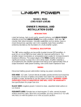
6
Class A 5.0
15
INSTALLATION STEP 5
LEVEL SETTING
The input levels are adjusted by means of the individual channel input level
controls located on the front of the amplifier. This is a unique dual-stage
circuit that adjusts both level and gain. This topology maintains better Signal
to Noise ratios even when using sources with minimal output.
In the ideal situation, all components in the audio system reach maximum
undistorted output at the same time. The reason is because an amplifier will
only make what comes into it bigger. So, if you send it a distorted signal from
the head unit, the amplifier is going to amplify distorted information. The
same thing holds true if an outboard processor or crossover begins to distort
before you have maximum output from the amplifier. By setting all
components to reach clipping at the same time, you can maximize the output
of your system. For the REFERENCE Class A amplifiers, follow the following
steps for the quickest, easiest means of setting the levels.
1. Turn the amp’s input levels to minimum position (fully counter-
clockwise).
2. Begin with the input level switch in the 0.5 - 5.0 Volt position.
3. Set source unit volume to approximately 3/4 of full volume.
4. While playing dynamic source material, slowly increase the amplifier’s
input level until a near maximum undistorted level is heard in the
system.
If your preamplifier / source unit has an extremely high output level, be sure to
pay attention to the clipping indicators located on the top of the amplifier.
These indicators will notify you if you are clipping the PREAMPLIFIER stage of
the amplifier. If the amplifier's output is distorted and the clipping lights are
not blinking, you are most likely clipping the OUTPUTS of the amplifier, or
driving the speaker to distortion.

14
INSTALLATION STEP 4
INSTALLATION AND MOUNTING
1. AMPLIFIER LOCATION
The REFERENCE Class A amplifiers employ highly efficient circuitry and a
unique Chassisink
TM
design to maintain lower operating temperatures.
Additional cooling may be required if the amplifier is located in a tightly
confined area or when driving especially low impedance loads at extremely
high levels.
When mounting the amplifier, it should be securely mounted to either a panel
in the vehicle or an amp board or rack that is securely mounted to the vehicle.
The mounting location should be either in the passenger compartment or in the
trunk of the vehicle, away from moisture, stray or moving objects, and major
electrical components. To provide adequate ventilation, mount the amplifier so
that there are at least two inches of freely circulating air above and to the sides
of it.
2. SWITCHES
Set the Coherent Stereo
TM
/Mixed-Mono/Bridged Mono and Amplifier crossover
switches on the bottom of the amplifier to the appropriate positions before
bolting down the amplifier (see pages 13 - 16). Be sure to replace the hole
plugs.
3. MOUNTING THE AMPLIFIER
a.Using the amplifier as a template, mark the mounting surface.
b.Remove the amplifier and drill the holes.
c.Mount the amplifier to the surface using the provided hardware.
4. WIRING
a.Run and connect the audio signal and remote turn-on cables to the
amplifier from the source unit.
b.Carefully run the positive cable from the amplifier to a fuse or circuit
breaker within 18” of the battery.
c. Connect the fuse or circuit breaker to the battery. Leave the circuit breaker
off or the fuse out until everything is bolted down.
d.Secure the ground cable to a solid chassis ground on the vehicle. It may
be necessary to sand paint down to raw metal for a good connection.
e.Double check each and every connection!
NOTE: There may be a sizable spark when connecting the power and ground
lead to the amplifier for the first time. Please see the comment on the previous
7
Key to Callouts
1. Fault LED - Indicates a blown fuse.
2. Power LED - Indicates amplifier power on.
3. Input Overload Indicators - Indicates the signal input level or input gain
level is too high.
4. Input Level Selector Switch - Selectable input sensitivity range from 0.2-
2 Volts RMS, or from 0.5-5 Volts RMS.
5. Left Channel Balanced / Unbalanced Input Selector Switch - Select
"Balanced" to use the 6 pin Balanced signal Input. Select "Unbalanced" to
use the RCA signal inputs.
6. Right Channel Balanced / Unbalanced Input Selector Switch - Select
"Balanced" to use the 6 pin Balanced signal Input. Select "Unbalanced" to
use the RCA signal inputs.
7. Main Fuse - Main power supply fuse. Replace only with the same value
fuse.
8. +12V - Connected to a fuse or circuit breaker, then to the battery's positive
post.
9. GND - Main ground connection. Bolt to a clean chassis ground in the
vehicle.
10. REM - Remote turn-on input from the head unit. Accepts +12V.
11. Speaker Output Connections - Left and right channels.
12. Input Level - Independent Left and Right channel input level controls.
13. Balanced Signal Input Connector - 6-pin Balanced signal input
connector for use with the Soundstream BLT Balanced Line Transmitter.
14. Inputs - Right and left channel RCA (Unbalanced ) inputs; only right
channel input is used in "Mono" mode.
15. Coherent Stereo/Bridge/Mixed Mono switch - Select "Bridge" for
bridged mono operation (use right channel input). Select "Stereo" for
coherent stereo operation. Select "Mixed Mono" for simultaneous stereo /
bridged mono operation.

8
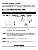
Class A
13
Amplifier Amplifier Fuse Battery Fuse /
Circuit Breaker
Class A 5.0
40 amp Maxi-Fuse 60 amp
Class A 10.0
80 amp Maxi-Fuse 100 amp
REFERENCE Class A Amplifier Fuse Values
(Continued from page 12)
of blown power supply fuse, the “Fault” indicator on the top panel will light.
The fuse is accessible from the front panel of the amplifier. See the chart
below to determine the fuse value. Never replace the fuses with a higher
value than what is supplied. This may result in amplifier damage and will
REMOTE TURN-ON
Connect the “Remote” to the turn-on lead from the source unit. When +12
volts is received, the amplifier will turn on.
SIGNAL CABLE
Use a high-quality cable that will be easy to install and has minimal signal loss
to guarantee optimum performance. Soundstream’s DL1 and SL1 are
ideal when using the Unbalanced RCA inputs. While using the Balanced DIN
input, use the cable supplied with the BLT.
SPEAKER CABLE
The REFERENCE Class A amps will accept up to 8 gauge speaker cable.
Use a high quality, flexible, multi-strand cable for best performance and
longevity. Soundstream Speaker120 & 160 (12 and 16 gauge) are ideal.
WIRING DIAGRAM

12
up to 10’ up to 20’
Class A 5.0
Soundstream Power40 or
Power80
Soundstream Power40 only
(4 ga.)
Class A 10.0
Soundstream Power40 only
(4 ga.)
Soundstream Power40 only
(4 ga.)
INSTALLATION STEP 3
WIRING
POWER AND GROUND
To ensure maximum output from your REFERENCE Class A amplifier, use
high quality, low-loss power and ground cables. The REFERENCE Class A
amplifiers will accept up to 4 gauge power and ground cables. Determine
Read this, or sparks will fly!
The Soundstream REFERENCE Class A amplifiers have extensive internal
power supply capacitance, called the Ultra-Low ESR Capacitance Bank.
Multiple small input power capacitors act as an internal "stiffening capacitor".
Because of the large amount of internal capacitance, there may be a sizable
spark when connecting the power and ground lead to the amplifier for the first
time. In order to charge the capacitor bank without a spark, we suggest you
do the following:
1. Connect the +12 volt cable to the amplifier and to the battery.
2. Connect one end of the ground cable to the chassis of the vehicle.
3. We have supplied a 150 ohm, 2 watt resistor with the amplifier. One leg
of the resistor has been connected to the ground terminal of the amplifier.
4. To charge the capacitor bank, touch the loose end of the ground cable to
the open leg of the resistor for at least 45 seconds.
CIRCUIT BREAKERS/FUSES
EXTERNAL
Like all audio components, the REFERENCE Class A amplifiers must be fused
near the battery. A fuse or circuit breaker must be located within 18” of the
battery. This will prevent a fire in the event of a shorted cable. See the chart
below to determine the correct fuse value.
INTERNAL
The REFERENCE Class A amplifiers are fused with Maxi-fuses. In the event
(Continued on page 13)
9
Key to Callouts
1. Fault LED - Indicates a blown fuse.
2. Power LED - Indicates amplifier power on.
3. LSE.Q Bypass Switch - Turns the LSE.Q on ("IN") or off ("OUT").
4. Input Overload Indicators - Indicates the signal input level or input gain level
is too high.
5. Input Level Selector Switch - Selectable input sensitivity range from 0.2-2
Volts RMS, or from 0.5-5 Volts RMS.
6. Left Channel Balanced / Unbalanced Input Selector Switch - Select
"Balanced" to use the 6 pin Balanced signal Input. Select "Unbalanced" to use
the RCA signal inputs.
7. Right Channel Balanced / Unbalanced Input Selector Switch - Select
"Balanced" to use the 6 pin Balanced signal Input. Select "Unbalanced" to use
the RCA signal inputs.
8. Main Fuse - Main power supply fuse. Replace only with the same value fuse.
9. +12V - Connected to a fuse or circuit breaker, then to the battery's positive
post.
10. GND - Main ground connection. Bolt to a clean chassis ground in the vehicle.
11. REM - Remote turn-on input from the head unit. Accepts +12V.
12. Speaker Output Connections - Left and right channels.
13. LSE.Q - Frequency and Q adjustments.
14. Input Level - Independent Left and Right channel input level controls.
15. Balanced Signal Input Connector - 6-pin Balanced signal input connector for
use with the Soundstream BLT Balanced Line Transmitter.
15. Inputs - Right and left channel RCA (Unbalanced ) inputs; only right channel
input is used in "Mono" mode.
16. Coherent Stereo/Bridge/Mixed Mono switch - Select "Bridge" for bridged
mono operation (use right channel input). Select "Stereo" for coherent stereo
operation. Select "Mixed Mono" for simultaneous stereo / bridged mono
operation.

10
INSTALLATION STEP 1
COHERENT STEREO™ /
MIXED-MONO / BRIDGED MONO
The REFERENCE Class A amplifiers have the ability to operate in any one of
the following modes:
Coherent Stereo™ with identical left and right stereo channels for
maximum fidelity. Best choice for satellite speakers. Use this mode unless
Mixed-Mono is necessary.
Mixed-Mono in order to drive stereo and mono simultaneously; works well
for center channels. It can be used anytime you need a summed mono
channel. Somewhat sacrifices sonic accuracy as additional circuitry is
introduced to one channel. In Mixed-Mono, the left channel is inverted, see
diagram below or on the bottom of the amplifier.
Bridged Mono for dedicated single channel operation; ideal for driving
subwoofers. It is also used when large amounts of power are necessary for
single speakers. In bridged mono, only the right channel input is active.
In bridged mono, only the right channel input is active.
NOTE: If you intend to drive a
REFERENCE Class A amplifier in Mono but
have stereo outputs from your crossover or
source unit, you can put the switch in
11
INSTALLATION STEP 2
BALANCED / UNBALANCED INPUT
The REFERENCE Class A amplifiers have the ability to accept either a
standard Unbalanced RCA signal inputs, or a Balanced "Pro Audio" inputs with
the use of the Soundstream BLT Balanced Line Transmitter or some other
balanced line audio source. Before installing your system, you should decide
The REFERENCE Class A amplifiers' signal inputs accept two ranges of input
signal levels: 0.2 - 2.0 Vrms, or 0.5 - 5.0 Vrms for both Balanced and
Unbalanced inputs. The input range switch position and level settings are
dependent upon the preamplifier / source unit output signal level. For the best
system Signal to Noise Ratio, we recommend that the input level controls be
set as far down as possible (rotated counter-clockwise), while maintaining an
acceptable level of output.
Using the "Unbalanced" RCA input
When using the Unbalanced RCA input, the RIGHT channel input signal
switch MUST be in the "UNBAL" position. Also, when first installing the
amplifier using this input configuration, we suggest that the left channel input
signal switch be in the "UNBAL" position as well. If you experience
alternator wine or other installation noise with both switches in the
"UNBAL" position, try moving the LEFT channel input signal switch to
the "BAL" position. This should remove any system noise due to
installation.
Using the "Balanced" RCA input
When using the Balanced 6-pin DIN input, both switches MUST be in the
"BAL" position. Also, we recommend that when using this input configuration,
the "INPUT LEVEL" switch be in the "0.5 - 5V" position, and the gains on the
UNBALANCED INPUT BALANCED INPUT
ADVANTAGES 1.Most preamplifier / source
units have "UNBAL" RCA
outputs. (Industry stan-
dard)
2.No Interface module is nec-
essary
1.Improved Signal to Noise
Ratio. (S/N Ratio)
2.Excellent noise cancellation
characteristics.
3.Immune to noise radiated in
the car audio environment.
NOTE: The pin
configuration shown
in the diagram is the
view looking into the
Balanced input jack
on the amplifier.
/