Chore-Time MW838E Floor Watering Operating instructions
- Type
- Operating instructions

Floor Watering Systems
Operator’s Manual
with
Installation Instructions
•
Operating Recommendations
•
Parts List
•
Troubleshooting Guide
•
Maintenance Information
MW838E32
June 1995

Floor Watering Operator’s Manual
•
Page 2
WARRANTY INFORMATION
Chore-Time equipment warrants each new product manufactured by it to be free from defects in material or
workmanship for one year from the date of initial installation by the original purchaser. If such a defect is
found by Chore-Time to exist within the one year period, Chore-Time will, at its option, (a)repair or replace
such product free of charge, F.O.B. the factory of manufacture, or (b) refund to the original purchaser the
original purchase price, in lieu of such repair or replacement.
Additional extended warranties are herewith provided to the original purchaser as follows:
1. RLX Fans, less motors, for three years from date of installation.
*2. Poultry feeder pans that become unusable within five years from date of installation.
Warranty prorated after three years usage.
3. MEAL-TIME Hog Feeder pans that become unusable within five years of
installation.
4. Rotating centerless augers, excluding applications involving High Moisture Corn
(exceeding 18%), for ten years from date of installation. Note: MULTIFLO and
applications involving High Moisture Corn are subject to a one year warranty.
5. Chore-Time manufactured roll-formed steel auger tubes for ten years from date of
installation.
*6. Laying cages that become unusable within ten years. Warranty prorated after three
years usage.
*7. ULTRAFLO Auger and ULTRAFLO Feed Trough (except ULTRAFLO Trough
Liners) are warranted for a period of five (5) years from date of original purchase
against repeated breakage of the auger or wear-through of the feed trough.
Conditions and limitations:
1. The product must be installed and operated in accordance with instructions published
by Chore-Time or warranty will be void.
2. Warranty is void if all components of a system are not supplied by Chore-Time.
3. This product must be purchased from and installed by an authorized Chore-Time dealer
or certified representative thereof, or the warranty will be void.
4. Malfunctions or failure resulting from misuse, abuse, negligence, alteration, accident,
or lack of proper maintenance shall not be considered defects under this warranty.
5. This warranty applies only to systems for the care of poultry and livestock. Other
applications in industry or commerce are not covered by this warranty.
Chore-Time shall not be liable for any consequential or special damage which any purchaser may suffer or
claim to have suffered as a result of any defect in the product. "Consequential" or "special damages" as used
herein include, but are not limited to, lost or damaged products or goods, costs of transportation, lost sales,
lost orders, lost income, increased overhead, labor and incidental costs and operational inefficiencies.
THIS WARRANTY CONSTITUTES CHORE-TIME’S ENTIRE AND SOLE WARRANTY AND
CHORE-TIME EXPRESSLY DISCLAIMS ANY AND ALL OTHER WARRANTIES, INCLUDING, BUT
NOT LIMITED TO, EXPRESS AND IMPLIED WARRANTIES AS TO MERCHANTABILITY, FITNESS
FOR PARTICULAR PURPOSE SOLD AND DESCRIPTION OR QUALITY OF THE PRODUCT
FURNISHED HEREUNDER.
Any exceptions to this warranty must be authorized in writing by an officer of the company. Chore-Time
reserves the right to change models and specifications at any time without notice or obligation to improve
previous models.
*See separate "WARRANTY ADDITION" as to these products
CHORE-TIME EQUIPMENT, A Division of CTB, Inc.
P.O. Box 2000, Milford, Indiana 46542-2000 U.S.A.

Floor Watering Operator’s Manual
•
Page 3
Table of Contents
Topic Page User*
Warranty Information - - - - - - - - - - - - - - - - - - - - - - - - - - - - - - - - 2 C, D
Inlet and Outlet Assemblies- - - - - - - - - - - - - - - - - - - - - - - - - - - - - 4 D, I
Prior to the Installation - - - - - - - - - - - - - - - - - - - - - - - - - - - - - - - 5 C, I
Installation Instructions - - - - - - - - - - - - - - - - - - - - - - - - - - - - - - 5 - 17 I
Control Panel Installation - - - - - - - - - - - - - - - - - - - - - - - - - - - - - 5 - 6 I
Suspension System Installation - - - - - - - - - - - - - - - - - - - - - - - - - - 7 - 9 I
Hanger and Channel Installation- - - - - - - - - - - - - - - - - - - - - - - - - - 10 - 11 I
Cup and Pipe Installation - - - - - - - - - - - - - - - - - - - - - - - - - - - - - 11 - 14 I
Anti-Roost Installation - - - - - - - - - - - - - - - - - - - - - - - - - - - - - - 15 - 16 I
Partial House Brooding - - - - - - - - - - - - - - - - - - - - - - - - - - - - - - 16 - 17 I
Connecting Hose Installation - - - - - - - - - - - - - - - - - - - - - - - - - - - 17 I
. . . Before Turning on the Water. . . - - - - - - - - - - - - - - - - - - - - - - - - 17 I
Maintenance of the Floor Watering System - - - - - - - - - - - - - - - - - - - - - 18 C
Maintenance Between Batches - - - - - - - - - - - - - - - - - - - - - - - - - - 18 C
Recommended Guidelines for Operation - - - - - - - - - - - - - - - - - - - - - - 19 C
Valve Repair - - - - - - - - - - - - - - - - - - - - - - - - - - - - - - - - - - - - 20 C
Valve Disassembly - - - - - - - - - - - - - - - - - - - - - - - - - - - - - - - - 20 C
Inspect the Parts - - - - - - - - - - - - - - - - - - - - - - - - - - - - - - - - - 20 C
Valve Reassembly - - - - - - - - - - - - - - - - - - - - - - - - - - - - - - - - 20 C
Installation of the Optional Water Meters - - - - - - - - - - - - - - - - - - - - - - 21 C, I
13228-L (Liter) & 13228-G (Gallon) Water Meter - - - - - - - - - - - - - - - - - - 21 C, I
13227 Water Meter and Connectors - - - - - - - - - - - - - - - - - - - - - - - - 21 C, I
Satellite Drinker - - - - - - - - - - - - - - - - - - - - - - - - - - - - - - - - - - 22 C, I
Drinker Installation - - - - - - - - - - - - - - - - - - - - - - - - - - - - - - - - 22 I
Satellite Drinker Operation - - - - - - - - - - - - - - - - - - - - - - - - - - - - 23 C
Satellite Drinker Maintenance - - - - - - - - - - - - - - - - - - - - - - - - - - - 23 C
Parts Listing - - - - - - - - - - - - - - - - - - - - - - - - - - - - - - - - - - - - 24 - 29 C, D, I
Troubleshooting Guidelines - - - - - - - - - - - - - - - - - - - - - - - - - - - - 30 C, D, I
*Legend: C = Customer • D = Distributor • I = Installer
IMPORTANT
Check shipment for damages and shortages.
All claims for damages or shortages resulting from shipment must be filed with the carrier.
All parts should be ordered by part number and description as given in the parts lists in this instruction
manual.
All parts are billed when shipped.
If a returned part is defective and within warranty, credit will be allowed against billing.
Repair parts information for PVC Floor Watering Systems is available on pages 19 through 27.

Floor Watering Operator’s Manual
•
Page 4
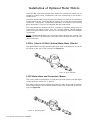
25665 Inlet Assembly (Standard) contains a pressure gauge so that individual line pressures can
be monitored. It is also used with the 25666 Continuous Outlet Assembly for partial-house brooding.
25667 Extended Inlet Assembly has a vertical extension pipe for where it is desired to raise the
inlet hose above the bird level such as for turkeys. It may only be used with the 8072 Deluxe Cage
Control Panel and overhead plumbed systems.
25668 Inlet Hanger Assembly w/Regulator is for use only with the 9275 Filter Control Panel. It
contains a regulator and pressure gauge for regulating the individual water line pressure.
25666 Continuous Outlet Assembly is for use where the waterer line must be interrupted to get
around a partition or for partial-house brooding. It contains a shut-off valve to shut off water to the
section not being used. It is used with a hose to go around the partition and a 25665 Inlet Assembly
to continue the waterer line. Cup and Pipe Assembly and Coupler are shown for reference only (not
included in 25666 Continuous Outlet Assembly).
Various Inlets, Outlets, and optional hook-ups are available for full and partial house
brooding, mid-line hook-ups, overhead plumbing or other variations to suit the
application. Typical installations are shown.

Floor Watering Operator’s Manual
•
Page 5
Prior to the Installation
It is extremely important to maintain good water quality with any watering sys-
tem. Good water quality maximizes performance of the equipment, minimizes
maintenance and repair, and increases the life of the system.
Pump the well for two days prior to hookup of the system to clear sand, mud,
or debris. CHORE-TIME recommends a water test by a reputable water treat-
ment company in the area. Water treatment and/or extra filtration may be re-
quired, depending on the water test results.
Incoming water pressure must be 40 p.s.i. (275 kPa) or higher for use with
CHORE-TIME equipment.
Incoming water supply should be at least a 1" (25 mm) diameter incoming line
(preferably PVC) from a single well. If there are two or more supply wells, the
incoming line should be larger. Also, depending on the distance from the
well(s) to the Control Panel, larger lines may be necessary.
Installation Instructions
It is suggested that at the beginning of each step, the installer should take time
to "lay out" the large parts--channels, pipes, etc.--in the approximate location
where they will be used. Hardware, tools, and small components can be con-
veniently carried in a carpenter’s apron. This way they will be at hand when
needed.
The following installation procedure is recommended.
1. Control Panel Installation
2. Install the suspension system, Adjustment Levelers, Hangers, and Inlet
and Outlet Hanger Assemblies.
3. Install Channel Sections.
4 Install the Cup and Pipe Assemblies.
5. Install hose from the Control Panel to waterer lines.
6. Install Anti-Roost System.
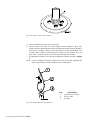
Control Panel Installation
The Filter Control Panel is used to remove foreign material from the incoming
water, and if necessary, add medication to the water.
The Regulator and Gauge Assembly is used to reduce the water pressure out
of the Filter Control Panel. Adjust the operating pressure as recommended in
the Quick Reference Sheet.
The Multiple Outlet Kit is used to provide additional hose hook-ups to supply
the waterer lines.
The Filter Control Panel and associated modules should be installed in a
convenient location where incoming and outgoing water supply lines can be
easily run. The Filter Control Panel must be out of the reach of birds.
The Filter Control Panel is shipped secured to a Mounting Board. The
Mounting Board and Filter Control Panel should be secured to a wall or post
using lag bolts (not supplied).
The Regulator and Gauge Assembly is shipped un-assembled. Assemble the
Regulator and Gauge Assembly components as specified in the instruction
(MW1076) shipped with the kit.

Floor Watering Operator’s Manual
•
Page 6
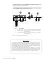
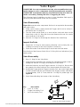
The Multiple Outlet Hook-Up Kit is shipped un-assembled. Assemble the com-
ponents to build a kit, as shown in Figure 1. If additional hook-ups are re-
quired, they must be ordered separately.
Connect the Regulator and Gauge Assembly to the Filter Control Panel, as
shown in Figure 1. To avoid air pockets in the system, do not route connecting
hoses over objects higher than the Control Panel.
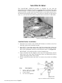
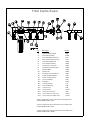
Key Description
1 Part No. 9275: Filter Control Panel (shipped assembled)
2 Part No. 9042: Regulator and Gauge Module (shipped
un-assembled)
3 Part No. 35484: Multiple Outlet Hook-Up Kit (shipped
un-assembled)
Figure 1. Control Panel Installation (front view)
Important
Chore-Time recommends an incoming water pressure between 40 p.s.i. (275
kPa) minimum and 125 p.s.i. (859 kPa) maximum for use with the Control Panel.
NOTE: FAILURE TO USE PIPE CUTTERS TO CUT THE CHORE-TIME PVC
FLOOR WATERING PIPE WILL VOID THE WARRANTY COVERAGE. THE
PIPE CUTTERS MUST BE PURCHASED LOCALLY.
For every 28" (711 mm) drop in height, water pressure increases 1 p.s.i. (7 kPa).
Therefore, if the Control Panel must be mounted at a different height than the
waterer line, this factor must be considered when setting operating pressures
at the control panel. Measure the operating pressure at the valve height.

Floor Watering Operator’s Manual
•
Page 7
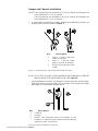
Suspension System Installation
The following installation instructions are for standard installations. For Partial
House Brooding the sections can be winched separately or together. Treat
each section as a standard installation and install as below.
1. Determine where the waterer line is to be installed and suspended. Mark
a straight line on the ceiling or rafters at this point using string or chalk
line, or winch cable temporarily attached with staples or nails.
2. Install screw hooks along the line at 8’ (2.4 m) intervals. An 8’ (2.4 m) cable
drop spacing is preferred but other spacings up to 10’ (3 m) may be used.
Existing winching can be used if it is in good condition and has no less than
1/8" (3.1 mm) main cable. Screw the threads all the way in to prevent
bending. The opening of the hooks must point away from the direction the
cable pulls. See Figure 2.
If the distance the waterer is to be raised is greater than the distance
between drops, stagger the hooks three inches (76 mm) to each side to
prevent the cable clamps from catching on the pulleys. See Figure 3.
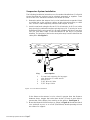
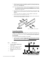
3. Mount the Manual Winch Bracket as shown in Figure 4. Mount the Winch
on a stud wall or post, or on a 2x8” (50x200 mm) board spanning at least
two rafters for support.
Key Description
1 Screw Hook opening facing oppo-
site direction of cable travel
2 Winch End
3 3/16” Winch Cable
4 3/32” Drop Cable
Figure 2. Screw Hook Installation

Floor Watering Operator’s Manual
•
Page 8
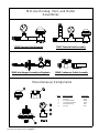
Key Description
3 Drop Cable
1 Winch Cable
2 Screw Hook Location
4 Distance Between Drops (8’ or 2.4 m)
5 Distance Waterer is to be raised
6 Pulley
7 Cable Clamp
Figure 3. Stagger the Screw Hooks, if necessary, to avoid interference.
Figure 4. Mounting the Manual Winch
4. Bolt the winch to the bracket and attach one end of the 1/8" (3.1 mm) cable
to the winch as shown in Figure 5. Unroll the 1/8" (3.1mm) cable along the
length of the waterer line.

Floor Watering Operator’s Manual
•
Page 9
5. Install a 3004 Pulley on each screw hook.
6. Cut a section of the 3/32" (2.3 mm) cable for each suspension drop. The
Cable should be approximately two feet (609 mm) longer than the distance
from floor to ceiling so that it can be attached at the top and bottom. Use
a 6428 Cable Clamp to attach the Drop Cable to the overhead 1/8" (3.1
mm) cable. Feed the other end of the cable through each pulley.
7. If Adjustment Levelers are to be used, thread the cable as shown in Figure
6.
Note: It may be helpful to hang a weight on the end of the line opposite the
winch, temporarily, until the waterer line is suspended.
Figure 5. Attach Cable to Winch Drum.
Key Description
1 Adjustment Leveler
2 Drop Cable
3 Hanger
Figure 6. Adjustment Leveler Installation

Floor Watering Operator’s Manual
•
Page 10
NOTE: IT IS CRITICAL THAT EACH HANGER IN THE INDIVIDUAL LINES BE
INSTALLED IN THE SAME DIRECTION. SEE Figure 8.
Install Adjustment Levelers and Hanger on all the drop lines in the system.
Keep the Hangers as level to the floor as possible. Use the winch to adjust
the height to a comfortable working level.
Hanger and Channel Installation
NOTE: If the suspension was installed on 8’ (2.4 m) centers, the Hangers are
to be installed on 4’ (1.2 m) centers.
If the suspension was installed on 10’ (3 m) centers, the Hangers are
to be installed on 5’ (1.5 m) centers.
1. It is possible to suspend the system, without using Adjusting Levelers, by
wrapping the cable as shown in Figure 7.
Key Description
1 Step 1: Loosely route the
cable as shown.
2 Step 2: Pull the cable
tight to secure to Hanger.
3 Drop Cable routed to main
cable.
Figure 8. Channel Installation (side view).
Key Description
1 Channel
2 Hanger
3 Notice: The Channels must be installed in the
Hangers as shown to allow free movement during
expansion and contraction.
Figure 7. Suspending the system without Adjustment Levelers.

Floor Watering Operator’s Manual
•
Page 11
2. Beginning at the incoming end of the line, slide the Channel into the Hang-
er. The Channel should be allowed to extend 6" (152 mm) past the inlet
end drop line. See Figure 10.
NOTE: The Channels must be installed so that the outside bend of the center
"V" is toward the larger, round opening. See Figure 8. This will allow
the hardware to pass through the Hangers without interference, during
expansion and contraction.
3. The Channels are belled at one end to allow them to easily fit the next
Channel. Use the 1/4-20 hardware to fasten the Channels together. See
Figure 9.
DO NOT SECURE THE CHANNEL TO THE HANGERS IN ANY WAY.
4. Install Channels to the outlet end of the line.
It may be necessary to cut the last Channel to length so that it extends past
the end hangers approximately 6" (152 mm).
Figure 9. Bolt the Channels together.
Cup and Pipe Installation
The PVC Floor Waterer System provides lines of cups with 12" (304 mm), 16"
(406 mm), 24" (609mm), 30" (762 mm), 40" (1.01 m), 48" (1.21 m), 60" (1.52
m), 80" (2.03 m), or 96" (2.43 m) spacings. Each cup provides adequate wa-
ter for 50 birds.
Several different Inlet End Assemblies are available.
1. Use PVC cement to glue the Inlet Assembly to the first section of Cup and
Pipe Assembly, as shown in Figure 10. MAKE SURE THE CUPS AND
DOME AIR RISER ARE IN-LINE BEFORE THE GLUE HARDENS.
Figure 10. Inlet Assembly Installation
Key Description
1 Gently, snap the waterer line
into the Hanger. Do Not Glue
at this time.
2 Glue Cup and Pipe Assembly
to the Inlet Assembly here.
3 Make sure the Cups are in
line with the Dome Air Riser.
4 Channel
5 Hanger

Floor Watering Operator’s Manual
•
Page 12
Directions for Use of PVC Cement
Follow directions on the container of PVC Cement for safe handling and best re-
sults.
1. Be sure pipe is cut off squarely. Remove dirt and burrs from outside and in-
side of the pipe ends.
2. Dry fit all parts before cementing. Pipe should fit into coupler, elbow, or valve
without applying excess force.
3. Surfaces to be joined should be clean and dry -- free from all dirt, oil, and
grease.
4. Apply cement to both surfaces to be joined. Apply cement sparingly but
evenly over the entire surface, leaving no bare spots.
5. Quickly join the two PVC components, giving them a twisting motion to bring
the joint into alignment as the parts are pushed together.
6. Keep light pressure on the joint for a few seconds to allow the joint to harden.
Important
Take special care to prevent dirt
and foreign objects from getting
into the water pipes.
2. The first Hanger will be located on the short section of pipe (nipple) just in
front of the Dome Air Riser. See Figure 10.
To install the pipe on the Hanger, apply pressure to the pipe to snap it up
into the Hanger. Do not apply PVC cement at this time.
If the 25668 Inlet Hanger Assembly w/Regulator is to be used, refer to the
parts list for the assembly diagram. It will be necessary to add an addition-
al Hanger to provide the necessary support. The additional Hanger should
be installed on the short section of pipe just prior to the Regulator. The ad-
ditional Hanger does not need a suspension drop line attached.
If the 25669 Inlet Hanger Assembly w/Regulator is to be used, it will be
necessary to remove the Hanger on the first drop line, since a Hanger is
factory installed.
3. Snap the first Cup and Pipe Assembly into the Hangers above it.
NOTE: While installing the pipe into the Hangers, a cup may fall at the
same location as the Hanger. If this occurs, install the Hanger to either
side of the cup approximately 2" (50 mm). No adjustments need to be made
to the location of the suspension drop line.
4. Install another section of Cup and Pipe on the next few Hangers.
5. Use a coupling (supplied) to glue the sections of Cup and Pipe together.
Do not install a Dome Air Riser on this joint.
MAKE SURE THE CUPS ON EACH PIPE ARE IN-LINE, BEFORE THE
GLUE HARDENS.

Floor Watering Operator’s Manual
•
Page 13
6. Hang the next section of Cup and Pipe.
Install a Dome Air Riser at this joint, as shown in Figure 11.
7. Hang the next section of Cup and Pipe, using a coupler to connect it to the
waterer line.
8. Continue hanging and connecting Cup and Pipe Assemblies to the outlet
end of the line.
REMEMBER to install a Dome Air Riser at every other joint!
9. The last section of Cup and Pipe may need to be cut so that when a cou-
pling and Outlet Assembly is installed, the Hanger can be positioned in the
location shown in Figure 12.
Key Description
1 Install a Dome Air Riser at every-other joint in the line.
Figure 11. Dome Air Riser Installation
Key Description
1 Glue Cup and Pipe
Assembly to the
Outlet Assembly,
using a Coupler.
2 Coupler
3 Outlet Assembly
10. Begin gluing the Hangers to the Cup and Pipe Assemblies at either end of
the waterer line. Glue as follows:
--GENTLY, bend the Cup and Pipe Assembly away from the bottom of the
Hanger, to provide an opening. See Figure 13.
--Using an oil can filled with PVC cement, pump two squirts of cement be-
tween the Hanger and the Cup and Pipe Assembly.
Figure 12. Outlet Assembly Installation

Floor Watering Operator’s Manual
•
Page 14
–Allow the pipe to fit back in the Hanger. MAKE SURE THE CUPS ARE
UPRIGHT BEFORE THE GLUE HARDENS.
–Repeat this procedure on both sides of each Hanger on the waterer line.
11. Install the pressure gauge shipped with the Inlet Assembly on the tee joint
at the inlet. Use teflon tape to seal the joint. See Figure 14.
After the installation, the gauge should be positioned directly under the
channel for maximum protection.
Key Description
1 Apply PVC Cement here (on both sides of
Hanger).
Hint: Use an oil can, filled with PVC Cement,
to easily direct cement under the Hanger.
Figure 13. Glue Hangers in place on Cup and Pipe Assembly
Figure 14. Glue Hangers in place on Cup and Pipe Assembly

Floor Watering Operator’s Manual
•
Page 15
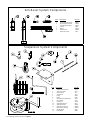
Anti-Roost Installation
Figure 15 shows an installed Anti-Roost system, refer to it as necessary.
1. Cut a Threaded Hanger in the location shown in Figure 16. A hacksaw
may be used to cut the Hanger. The lower portion of the Hanger will not
be used, and may be discarded.
It will be necessary to cut a Threaded Hanger for each inlet and outlet end
in the system.
2. Thread an eyebolt into the eye in the top of the Hanger, as shown in Fig-
ure 15.
3. Install the Hanger end of the Channel. Do not fasten the Hanger to the
Channel in any way, the cable will hold the Hanger in place when it is in-
stalled.
4. Thread the cable through the hole in the top of the Hangers.
5. Thread the cable through the eyebolt, making a loop, and clamp, using a
split-bolt cable clamp.
6. The spring should be installed near the center of the Anti-Roost line, at
least 2‘ (610 mm) from the closest Hanger.
Cut the cable in the desired spring location and install, using split-bolt ca-
ble clamps.
Figure 15. Glue Hangers in place on Cup and Pipe Assembly
Figure 16. Cut Hanger for Anti-Roost System
Key Description
1 Use hacksaw to cut
here. Discard lower
portion of Hanger

Floor Watering Operator’s Manual
•
Page 16
7. Thread the cable through the eyebolt, making a loop, and loosely clamp,
using a split-bolt cable clamp.
Put 1/2" to 1" (12 to 25 mm) of stretch in the spring so there is adequate
tension on the cable. If the Channel begins to buckle, reduce the amount
of tension.
Tighten the cable clamp to hold the stretch.
8. Mount the Poultry Trainer on a secure post or wall near the waterer line.
THE ANTI-ROOST SYSTEM MUST BE GROUNDED THROUGH THE
POULTRY TRAINER. The channels must be grounded to the poultry train-
er ground connection for best operation.
Chore-Time recommends operating the Anti-Roost system on a separate
circuit so it can be shut-off with a switch at the door. This will help prevent
the birds from becoming flighty.
Partial House Brooding
To partial house brood with the Chore-Time PVC Floor Watering System, in-
stall the line in two or more sections-- each with inlet and outlet assemblies.
Place the curtain, if used, between the two sections of the line. Use a section
of hose to attach the 25666 Continuous Outlet Hanger Assembly of one line to
the 25665 Inlet Hanger Assembly of the second section.
Line sections may be suspended using one winch; or separate independent
suspensions can be used. Figure 17 shows an example of a PVC floor water-
ing line adapted for a house with curtain and partial house brooding. NOTE:
Satellite drinker units for use in conjunction with brooders can be ordered as
optional equipment for the PVC Floor Watering System.
Connecting Hose Installation
Install the hoses from the waterer lines to the control panel outlets or overhead
supply. Be careful hose does not kink when waterers are raised off the floor.
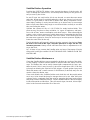
Figure 17. Partial House Brooding.
Key Description
1 Curtain

Floor Watering Operator’s Manual
•
Page 17
Start-Up Procedure
--flush all lines at maximum pressure
--be sure filters are installed correctly
--check that the cups sit upright
--check for any leaking or dripping pipe connections
--check that Float Balls are installed in brooding area
--clean all dirt out of cups
--flush all air out of lines
--maintain house temperature above freezing or drain lines and cups completely.

Floor Watering Operator’s Manual
•
Page 18
Maintenance of the Floor Watering
System
CHORE-TIME Floor Watering System components require very little
maintenance; the various components are designed and molded from
PVC plastic to provide maximum service with minimal maintenance.
Routine maintenance, however, will help guarantee good service and
prolong the life of the equipment.
When the system is new, monitor water pressures closely. This will be
helpful in determining whether dirt particles, sand, or other particles are
present in the water supply. It will also help determine frequency of filter
cartridge cleaning and/or replacement.
Check the water filter periodically and clean as necessary. Use the pres-
sure gauges on the control panel as guidelines. When pressure drops
across the filter, it’s time to clean or replace the filter cartridge. It’s a
good idea to keep extra filter cartridges on hand.
CHORE-TIME recommends a 20 micron cartridge. Replacement Car-
tridges are available from CHORE-TIME (Order Part No. 7723).
While in operation, flush the system thoroughly every 8 weeks (mini-
mum) to remove algae or trash that builds up in the lines. NOTE THAT
THIS IS MINIMUM! Some installations may require more frequent main-
tenance.
If algae growth becomes a problem, CHORE-TIME recommends use of
a bleach solution; see the "Recommendations and Guidelines" section
for details.
Walk lines daily to monitor water level in cups. If adjustment is required,
make the necessary pressure adjustments at the pressure regulator.
For additional information, see the "Operator’s Troubleshooting Guide"
in this manual.
MAINTENANCE BETWEEN BATCHES
--flush all air out of the lines
--flush each line at full pressure for ten minutes to remove deposits
and sediments
--check pressure drop across water filter--clean or replace if neces-
sary
--check pressure gauges, regulators, and shut off valves for proper
operation
--maintain house temperatures above freezing or drain lines and
cups completely
--Also, spot check dome air risers periodically. Replace diaphragms
that are "ballooned" or stretched.

Floor Watering Operator’s Manual
•
Page 19
Recommendations and Guidelines for
Operation
The CHORE-TIME Floor Watering System requires a minimum incoming
water pressure of 40 p.s.i. (275 kPa) to the Control Panel Regulators. THIS
IS THE MINIMUM PRESSURE. Recommended pressure is 40 to 60 p.s.i.
(275 to 412 kPa).
For best operation, set the pressure at the Control Panel according to the
recommendations below. Check the pressure gauge at the waterer line to
see that this pressure is achieved at the valves. Elevation differences be-
tween the two locations may require adjustment of the control panel pres-
sure setting to achieve the desired pressure at the valves. Twenty-eight
inches (71 cm) of water column equals one pound pressure.
Operation During Grow-out
WEEK 1 Start birds with Float Balls on all cups in brooding area. Set line
pressure at 3-5 p.s.i. (20-34 kPa) on systems with short triggers and
large float balls. Set pressure at 2-3 p.s.i. (14-20 kPa) on systems with
spring valves and large float balls. Water lines should be resting on the
litter for easy access by the birds.
WEEK 2 Remove Float Balls at 7 to 10 days of age. Reduce pressure to 3-4
p.s.i. (20-34 kPa) for several days to allow easy triggering of the
valves. Begin to raise the line off the floor. Keep the lip of the cup even
with the bird’s back.
WEEK 3 to full age. Maintain proper water cup height throughout the grow-out.
After 4 weeks, maintain water pressure at 6-8 p.s.i. (41-55 kPa). If a
lower water level is desired on large birds, increase the water
pressure slightly.
It should never be necessary to operate above 8 p.s.i. (55 kpa).
Water Quality
Water Quality is very important for proper operation of the system. Consid-
er the following:
Hardness- (Calcium and Magnesium) above 200 ppm (parts per million) a
water softener should be used.
PH - under 6.5 a neutralizing filter is recommended.
Iron - above 0.5 ppm (parts per million) should be treated with a water soft-
ener, a mechanical filtration system, or chlorination depending on raw wa-
ter hardness.
Precautions
1. Do not over chlorinate. The maximum concentration is 5 ppm (parts per
million) for extended periods and 10 ppm for flushing only. Do not chlo-
rinate 2 days before or after medication is used.
To Chlorinate: Mix a stock solution of 3/4 ounces of household chlorine
bleach (5% Sodium Hypochlorite) per gallon, or 5.9 ml of bleach per li-
ter, of water. Set the proportioner to dispense at a rate of one ounce
per gallon or 7.8 ml per liter.
2. Some vitamins and medications are syrup type liquids or are sugar
based. Avoid these types of compounds. These compounds may leave
a slimy deposit on the valve seals preventing them from sealing prop-
erly.
3. Some pumps and/or special purpose gas injectors may add excessive
air to the water supply. For proper operation of the system in these cas-
es, an Air Remover Kit is recommended to remove excess air from the
system. Contact your local CHORE-TIME distributor.

Floor Watering Operator’s Manual
•
Page 20
Valve Repair
CHORE-TIME does not recommend servicing valve assemblies due to po-
tential damage to valve components during disassembly and assembly.
CHORE-TIME recommends replacing any malfunctioning valve that can-
not be corrected by flushing the lines or triggering the valve.
The following Repair Guidelines are given in case immediate field repair is
necessary and replacement valves are not available.
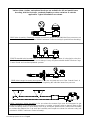
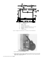
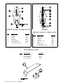
Valve Disassembly
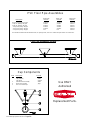
Figure 18 shows the valve components. Refer to it as required to disassemble
and repair valves.
1. Using a pair of pliers, gently smash the Trigger until it can be easily re-
moved from the "O" Ring Pin.
2. Turn the Valve upside down on a wood surface and push down on the
Valve Body so the "O" Ring Pin forces the Bottom Insert out. Be careful
not to bend the "O" Ring Pin.
3. Push the "O" Ring Pin out through the bottom of the Valve Body.
Inspect the Parts
1. Inspect the "O" Ring for trash and any deformity: such as being flat, cut,
or fitting too loosely on the shaft. Replace if necessary.
2. Check the inside of the Valve Body for trash and rinse with water.
Discoloration of the Reverse Check Pin or "O" Ring Pin is an indication of poor
water quality.
Valve Reassembly
1. Drop "O" Ring Pin into Valve Body.
2. Using the Valve Assembly Tool, position the Valve Body upright on the as-
sembly tool with the "O" Ring Pin sticking out of the orifice.
3. Insert the Deflector and new Trigger onto the "O" Ring Pin. Be sure that
the cupped side of the Deflector faces down towards the Valve Body.
4. Holding the Trigger with the Trigger Assembly Tool, tap on the Trigger with
a small hammer until the space between the Trigger and the Valve Body
is approximately 1/16” (1.5 mm) with the "O"-Ring Pin pulled tight. See
Figure 18.
5. Press Bottom Bushing into bottom of the Valve Body.
Figure 18. Valve Repair Diagram
Key Description
1 1/16” (1.5 mm)
2 Trigger Assembly Tool
3 Valve Assembly Tool
Page is loading ...
Page is loading ...
Page is loading ...
Page is loading ...
Page is loading ...
Page is loading ...
Page is loading ...
Page is loading ...
Page is loading ...
Page is loading ...
Page is loading ...
Page is loading ...
-
 1
1
-
 2
2
-
 3
3
-
 4
4
-
 5
5
-
 6
6
-
 7
7
-
 8
8
-
 9
9
-
 10
10
-
 11
11
-
 12
12
-
 13
13
-
 14
14
-
 15
15
-
 16
16
-
 17
17
-
 18
18
-
 19
19
-
 20
20
-
 21
21
-
 22
22
-
 23
23
-
 24
24
-
 25
25
-
 26
26
-
 27
27
-
 28
28
-
 29
29
-
 30
30
-
 31
31
-
 32
32


Chore-Time MW838E Floor Watering Operating instructions
- Type
- Operating instructions
Ask a question and I''ll find the answer in the document
Finding information in a document is now easier with AI
Related papers
-
 Chore-Time MW1186H Nipple Watering Installation and Operators Instruction Manual
-
 Chore-Time MW1186G Nipple Watering Installation and Operators Instruction Manual
-
 Chore-Time MW2392D STEADI-FLOW® & RELIA-FLOW® Nipple Drinking System Installation and Operators Instruction Manual
-
 Chore-Time MW1186E Nipple Watering Installation and Operators Instruction Manual
-
 Chore-Time MW1001B K-Valve Inlet Operating instructions
-
 Chore-Time MW1520A Filter Control Panel Operating instructions
-
 Chore-Time MW2364A Nipple Pipe Installation guide
-
 Chore-Time MF1288C MULTI-LIFT™ Winch System Installation and Operators Instruction Manual
-
 Chore-Time MW1520B Filter Control Panel Operating instructions
-
 Chore-Time MW2351B Watering Regulator User guide


Other documents
-
Martha Stewart Living 0463720310 Installation guide
-
Osprey WISE Operating instructions
-
 Water Source SPC250 Operating instructions
-
 T & S Brass & Bronze Works B-1996-03 Datasheet
-
 Tigon TW-0 Spring Balancer, Tool Balancer User manual
-
Kärcher 2.645-010.0 Datasheet
-
 Behlen Country SF-2C Assembly Instructions Manual
-
 T & S Brass & Bronze Works MV-3516-21 Datasheet
-
PREMIER1 54022519 User manual
-
Everbilt THD1020 Operating instructions


