Page is loading ...

Nipple Watering
Installation & Operator’s Instruction Manual
1186-52 7/99
MW1186ESeptember 1999

Chore-Time Warranty Chore-Time Nipple Watering
2
MW1186E
Chore-Time Equipment warrants each new product manufactured by it to be free from defects in material or
workmanship for one year from the date of initial installation by the original purchaser. If such a defect is found
by Chore-Time to exist within the one year period, Chore-Time will, at its option, (a) repair or replace such
product free of charge, F.O.B. the factory of manufacture, or (b) refund to the original purchaser the original
purchase price, in lieu of such repair or replacement.
Conditions and limitations:
1. The product must be installed and operated in accordance with instructions published by Chore-Time or
warranty will be void.
2. Warranty is void if all components of a system are not supplied by Chore-Time.
3. This product must be purchased from and installed by an authorized Chore-Time dealer or certified
representative thereof, or the warranty will be void.
4. Malfunctions or failure resulting from misuse, abuse, negligence, alteration, accident, or lack of proper
maintenance shall not be considered defects under this warranty.
5. This warranty applies only to systems for the care of poultry and livestock. Other applications in industry
or commerce are not covered by this warranty.
Chore-Time shall not be liable for any Consequential or Special Damage which any purchaser may suffer or
claim to have suffered as a result of any defect in the product. “Consequential” or “Special Damages” as used
herein include, but are not limited to, lost or damaged products or goods, costs of transportation, lost sales, lost
orders, lost income, increased overhead, labor and incidental costs and operational inefficiencies.
THIS WARRANTY CONSTITUTES CHORE-TIME’S ENTIRE AND SOLE WARRANTY AND CHORE-
TIME EXPRESSLY DISCLAIMS ANY AND ALL OTHER WARRANTIES, INCLUDING, BUT NOT
LIMITED TO, EXPRESS AND IMPLIED WARRANTIES AS TO MERCHANTABILITY, FITNESS FOR
PARTICULAR PURPOSE SOLD AND DESCRIPTION OR QUALITY OF THE PRODUCT FURNISHED
HEREUNDER.
Any exceptions to this warranty must be authorized in writing by an officer of the company. Chore-Time reserves
the right to change models and specifications at any time without notice or obligation to improve previous models.
CTB Inc.
P.O. Box 2000 • Milford, Indiana 46542-2000 • U.S.A.
Phone (219) 658-4101 • Fax (800) 333-4191
E-Mail: [email protected] • Internet: http//www.ctbinc.com
Chore-Time Warranty

Contents
Topic Page User
MW1186E
3
* Legend: C = Customer (end user), D = Distributor (sales), I = Installer of equipment
Chore-Time Warranty . . . . . . . . . . . . . . . . . . . . . . . . . . . . . . . . . . . . . . . . . . . . . . . . 2 C,D
Support Information . . . . . . . . . . . . . . . . . . . . . . . . . . . . . . . . . . . . . . . . . . . . . . . . . . . . . . .5
General. . . . . . . . . . . . . . . . . . . . . . . . . . . . . . . . . . . . . . . . . . . . . . . . . . . . . . . . . . . . . 5 C
Distributor and Installer Information . . . . . . . . . . . . . . . . . . . . . . . . . . . . . . . . . . . . . . . . . .5
About This Manual. . . . . . . . . . . . . . . . . . . . . . . . . . . . . . . . . . . . . . . . . . . . . . . . . . . 6 C,D,I
Tools for Installation . . . . . . . . . . . . . . . . . . . . . . . . . . . . . . . . . . . . . . . . . . . . . . . . . 6 C,D,I
General Information. . . . . . . . . . . . . . . . . . . . . . . . . . . . . . . . . . . . . . . . . . . . . . . . . . 6 C,D,I
Planning the System Layout . . . . . . . . . . . . . . . . . . . . . . . . . . . . . . . . . . . . . . . . . . . 8 C,D,I
Preferred Layout . . . . . . . . . . . . . . . . . . . . . . . . . . . . . . . . . . . . . . . . . . . . . . . . . . . . . . . . . .8
Alternate Layout #1 . . . . . . . . . . . . . . . . . . . . . . . . . . . . . . . . . . . . . . . . . . . . . . . . . . . . . . .8
Alternate Layout #2 . . . . . . . . . . . . . . . . . . . . . . . . . . . . . . . . . . . . . . . . . . . . . . . . . . . . . . .9
Planning the System Layout (continued) . . . . . . . . . . . . . . . . . . . . . . . . . . . . . . . . . 9 C,D,I
Suspension System Installation . . . . . . . . . . . . . . . . . . . . . . . . . . . . . . . . . . . . . . . . . 9 I
Assembling and Hanging the Water Line . . . . . . . . . . . . . . . . . . . . . . . . . . . . . . . . 12 I
Filter Control Panel Installation . . . . . . . . . . . . . . . . . . . . . . . . . . . . . . . . . . . . . . . . 18 I
Flushable Filter Control Panel Installation . . . . . . . . . . . . . . . . . . . . . . . . . . . . . . . 19 I
Anti-Roost Installation. . . . . . . . . . . . . . . . . . . . . . . . . . . . . . . . . . . . . . . . . . . . . . . . 20 I
Installing the Flush System . . . . . . . . . . . . . . . . . . . . . . . . . . . . . . . . . . . . . . . . . . . . 22 I
Filter Control Panel with Step Regulator . . . . . . . . . . . . . . . . . . . . . . . . . . . . . . . . . . . . . . 24
Parts Listing . . . . . . . . . . . . . . . . . . . . . . . . . . . . . . . . . . . . . . . . . . . . . . . . . . . . . . . . 24 C,D,I
Flushable Filter Control Panel . . . . . . . . . . . . . . . . . . . . . . . . . . . . . . . . . . . . . . . . . . . . . . 25
Chore-Time Nipple Inlet Assembly . . . . . . . . . . . . . . . . . . . . . . . . . . . . . . . . . . . . . . . . . . 26
Slope Compensator Assembly . . . . . . . . . . . . . . . . . . . . . . . . . . . . . . . . . . . . . . . . . . . . . . 27
Mid Line Stand Tube Assembly. . . . . . . . . . . . . . . . . . . . . . . . . . . . . . . . . . . . . . . . . . . . . 27
Stand Tube Outlet Assembly . . . . . . . . . . . . . . . . . . . . . . . . . . . . . . . . . . . . . . . . . . . . . . . 28
Nipple Waterer Mini Drinker . . . . . . . . . . . . . . . . . . . . . . . . . . . . . . . . . . . . . . . . . . . . . . . 29
Nipple Waterer Miscellaneous Components . . . . . . . . . . . . . . . . . . . . . . . . . . . . . . . . . . . 30
Nipple Waterer Miscellaneous Components . . . . . . . . . . . . . . . . . . . . . . . . . . . . . . . . . . . 31
Miscellaneous Kits and Components . . . . . . . . . . . . . . . . . . . . . . . . . . . . . . . . . . . . . . . . . 32
Flush Manifold Kit Part. . . . . . . . . . . . . . . . . . . . . . . . . . . . . . . . . . . . . . . . . . . . . . . . 32
Miscellaneous Hose Components . . . . . . . . . . . . . . . . . . . . . . . . . . . . . . . . . . . . . . . . 32
Mid Line Shut-Off Kit. . . . . . . . . . . . . . . . . . . . . . . . . . . . . . . . . . . . . . . . . . . . . . . . . 32
Mid Line Shut-Off Kit with Flush. . . . . . . . . . . . . . . . . . . . . . . . . . . . . . . . . . . . . . . . 32
Mid Line Shut-Off Kit with Flush and Shocker Components. . . . . . . . . . . . . . . . . . . 32
Water Medicator . . . . . . . . . . . . . . . . . . . . . . . . . . . . . . . . . . . . . . . . . . . . . . . . . . . . . 32

Contents -
continued
Topic Page User
4
MW1186E
Water Meters . . . . . . . . . . . . . . . . . . . . . . . . . . . . . . . . . . . . . . . . . . . . . . . . . . . . . . . . 32
Low Pressure Regulator Repair Kit. . . . . . . . . . . . . . . . . . . . . . . . . . . . . . . . . . . . . . . 32
Suspension System Components . . . . . . . . . . . . . . . . . . . . . . . . . . . . . . . . . . . . . . . . . . . . 33
Chore Time Nipple Watering Quick Reference Sheet . . . . . . . . . . . . . . . . . . . . . . 34 C,D,I
1 - 3 Days . . . . . . . . . . . . . . . . . . . . . . . . . . . . . . . . . . . . . . . . . . . . . . . . . . . . . . . . . . . . . . 34
3 - 21 Days . . . . . . . . . . . . . . . . . . . . . . . . . . . . . . . . . . . . . . . . . . . . . . . . . . . . . . . . . . . . . 34
21 Days - Grow-Out . . . . . . . . . . . . . . . . . . . . . . . . . . . . . . . . . . . . . . . . . . . . . . . . . . . . . . 34
Operational Guidelines . . . . . . . . . . . . . . . . . . . . . . . . . . . . . . . . . . . . . . . . . . . . . . . 35 C
Troubleshooting Guidelines. . . . . . . . . . . . . . . . . . . . . . . . . . . . . . . . . . . . . . . . . . . . 35 C,I
Guide to Cleaning Water Lines. . . . . . . . . . . . . . . . . . . . . . . . . . . . . . . . . . . . . . . . . 36 C,I
Standard Cleaning Procedure . . . . . . . . . . . . . . . . . . . . . . . . . . . . . . . . . . . . . . . . . . . . . . . 36
Regular Maintenance . . . . . . . . . . . . . . . . . . . . . . . . . . . . . . . . . . . . . . . . . . . . . . . . . . . . . 36
End of Grow Out Cleaning. . . . . . . . . . . . . . . . . . . . . . . . . . . . . . . . . . . . . . . . . . . . . . . . . 36
Between Flocks. . . . . . . . . . . . . . . . . . . . . . . . . . . . . . . . . . . . . . . . . . . . . . . . . . . . . . . . . . 36
Water Quality . . . . . . . . . . . . . . . . . . . . . . . . . . . . . . . . . . . . . . . . . . . . . . . . . . . . . . . 37 C,I

Chore-Time Nipple Watering General
MW1186E
5
Support Information
This manual is designed to provide comprehensive planning, installation, operation, and parts listing information.
The Table of Contents provides a convenient overview of the information in this manual. The Table of Contents
also specifies which pages contain information for the sales personnel, installer, and consumer (end user).
IMPORTANT: CE stands for certified Europe. It is a standard which
equipment must meet or exceed in ordered to be sold in Europe. CE provides
a benchmark for safety and manufacturing issues. CE is required only on
equipment sold in Europe.
Chore-Time Equipment recognizes CE Mark and pursues compliance in all
applicable products. Fill in the CE-Mark serial number in the blank space
provided for future reference.
Distributor and Installer Information
General
(CE-mark serial number)
Please fill in the following information about your Product.
Keep this manual in a clean, dry place for future reference.
Distributor’s Name___________________________________________________
Distributor’s Address ________________________________________________
Distributor’s Phone _______________________Date of Purchase ___________
Installer’s Name _____________________________________________________
Installer’s Address___________________________________________________
Installer’s Phone _______________________ Date of Installation ___________
System Specifications________________________________________________
___________________________________________________________________

About This Manual Chore-Time Nipple Watering
6
MW1186E
The intent of this manual is to help you in two ways. One is to follow step-by-step in
the order of assembly of your product. The other way is for easy reference if you have
questions in a particular area.
Important ! Read ALL instructions carefully before starting construction.
Important ! Pay particular attention to all SAFETY information.
• Metric measurements are shown in millimeters and in brackets, unless otherwise
specified. “ " ” equals inches and “ ' ” equals feet in English measurements.
Examples:
1" [25.4]
4' [1 219]
• Optional equipment contains necessary instructions for assembly or operation.
• Major changes from the last printing will be listed on the back cover.
• This Planning Symbol is used in areas where planning needs to take place before
construction continues.
• Very small numbers near an illustration (i.e.,
1257-48) are identification of the graphic,
not a part number.
It is extremely important to maintain good water quality. Good water quality
maximizes performance of the equipment, minimizes maintenance and repair, and
increases the life of the system. The water should be free of foreign particles.
Pump the well prior to hookup of the system to clear sand, mud, or debris. CHORE-
TIME recommends a water test by a reputable water treatment company in the area.
Water treatment and/or extra filtration may be required, depending on the water test
results.
CHORE-TIME recommends an incoming water pressure between 40 p.s.i. [2.9 kg/
cm
2
] minimum and 125 p.s.i. [8.8 kg/cm2] maximum for use with the 29950 Control
Panel and 35308 Step Regulator. A pressure of 45 p.s.i. [3.2 kg/cm
2
] is best.
For every 28" [711 mm] drop in height, water pressure increases one pound. Measure
the operating pressure at the water line height.
About This Manual
Tools for Installation
1 Regular Screwdriver 6 Bolt Cutters or Hack Saw
2 Locking Pliers 7 PVC Cleaning Solvent
3 File 8 Electrical Drill and Drill Bits
4 Saw to cut PVC Tubes 9 Another Person to help
5 Screw-Hook Driver
General Information

Chore-Time Nipple Watering General Information
MW1186E
7
Incoming water supply should be at least a 1" [25 mm] diameter incoming line
(preferably PVC) from a single well. If there are two or more supply wells, the supply
line should be larger. Also depending on the distance from the well(s) to the Filter
Control Panel, larger lines may be required.
The suspension system must be correctly installed to insure proper operation of the
system. This manual includes the suspension installation information.
The CHORE-TIME Nipple Drinker is available with Nipples spaced 6" [150 mm],
8" [200 mm], 10" [250 mm], 12" [300 mm], 15" [380 mm], 20" [508 mm], or 24"
[610 mm] on the 10’ [3 m] pipe.
Water lines up to 400’ [122 m] may be supplied using (1) Inlet Assembly. Water lines
over 400’ [122 m] must be split in the center of the house and supplied with (2) Inlet
Assemblies. However the management of the lines over 250’ [76 m] becomes more
critical. They must be kept very level, flushed, and cleaned several times per flock.
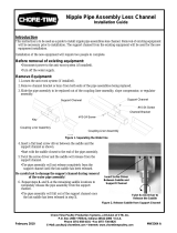
The CHORE-TIME Nipple Drinker is available with the standard Support Channel
for broiler applications. The Chore-Time Nipple Drinker is also available with the
heavy Support Channel for pullets and breeders. Figure 1 shows the difference
between the standard and heavy Support Channel with and standard and Button
Nipple Assemblies.
Figure 1. Various Drinker Styles (Side View)
Item Description
1 Standard Support Channel
2 Heavy Duty Support Channel
3 Standard Nipple Assembly
4 Button Nipple Assembly
1186-53 7/99
1 2
3 4 3 4

Planning the System Layout Chore-Time Nipple Watering
8
MW1186E
The diagrams below reflect approved system layouts. Use these diagrams as
guidelines. Your system layout may be different.
Preferred Layout
Alternate Layout #1
Planning the System Layout
1186-54 7/99
Outlet
Sight Tube
Outlet
Sight Tube
Outlet
Sight Tube
Outlet
Sight Tube
Inlet Inlet
Inlet Inlet
Inlet Inlet
Inlet Inlet
Curtain
Recommended Maximum Length 400'
Garden Hose
(Flush Line)
Garden Hose
(Flush Line)
Mid Line Stand Tube Kit (Needed for Lines Above 150' Long)
1186-55 7/99
Outlet
Sight Tube
Outlet
Sight Tube
Outlet
Sight Tube
Outlet
Sight Tube
Outlet
Sight Tube
Outlet
Sight Tube
Outlet
Stand Tube
Outlet
Stand Tube
Inlet Inlet
Inlet Inlet
Garden Hose
Garden Hose
Recommended Maximum Length 250'
Curtain
Garden Hose (Flush Line)
Mid Line Stand Tube Kit
(
Needed for Lines Above 150' Lon
g)

Chore-Time Nipple Watering Planning the System Layout (continued)
MW1186E
9
Alternate Layout #2
The following installation instructions are for standard installations. For Partial
House Brooding, the sections can be winched separately or together. Install each
section as a separate section.
1. Determine where the water line is to be installed. Mark a straight line on the
ceiling or rafters at this point using string or chalk line, or winch cable
temporarily attached with staples or nails.
2. For installations using wood trusses, the standard screw hook or the optional
Ceiling Hook may be used to hold the pulley Assemblies.
For installations using steel trusses, the Ceiling Hooks are available to hold the
pulley Assemblies.
Screw Hook Installations: Install screw hooks along the line at 8’ [2.4 m] or
10’ [3 m] intervals.
Screw the threads all the way in to prevent bending. The opening of the hooks
must point away from the direction the cable pulls. See Figure 2.
Figure 2. Screw Hook Installation (side view)
Planning the System Layout (continued)
1186-56 7/99
Recommended 300' - Maximum Length 400'
Curtain for Brood Area
Mid Line Stand Tube
(
Needed for Lines Above 150' Lon
g)
Outlet
Sight Tube
Outlet
Sight Tube
Garden Hose
(Flush Line)
Mid Line
Shut Off Kit
Mid Line
Shut Off Kit
Mid Line
Stand Tube
Mid Line
Stand Tube
Inlet
Inlet
Inlet
Inlet
Suspension System Installation
1 2
3
4
1186-71 8/99
Item Description
1 Screw Hook Opening
2 Direction of Cable pull
3 1/8" [3 mm] Cable
4 3/32" [2 mm] Cable

Suspension System Installation Chore-Time Nipple Watering
10
MW1186E
Ceiling Hook Installations: Install Ceiling Hooks along the line at 8’ [2.4 m] or
10’ [3 m] intervals. If the Ceiling Hook is to be secured with bolts or self-tapping
screws, install as shown in Figure 3. The Ceiling Hooks may be welded in place,
if desired, instead of bolting.
Figure 3. Ceiling Hook Installation (side view)
Note: If the distance the waterer is to be raised is greater than the distance
between the pulleys, offset the pulleys from each other approximately
3" [75 mm].
Figure 4. Offset the Screw/Ceiling Hooks (side view)
3. After the Screw Hooks or Ceiling Hooks have been secured to the trusses,
install the pulley assemblies as shown in Figures 2 & 3. Make sure the Screw
Hooks or Ceiling Hooks are pointing in the proper direction (opposite the
winch).
1186-72 8/9
9
1
2
Item Description
1 Secure with bolts and nuts
or self-taping screws
2 Swivel Pulley
1186-57 8/99
1
2 3
5
4
Item Description
11/8" [3 mm] Winch Cable
2 Screw Hook Location
3 Drop Cable or Cord
4 Distance of Cable Trevel
5 Distance Water Line is to be Raised

Chore-Time Nipple Watering Suspension System Installation
MW1186E
11
4. Mount the Split Drum Winch as shown in Figure 4. Mount the winch to the
ceiling or on a 2x8" [50x200 mm] board spanning at least two rafters for
support. Use at least (4) 1/4" lag screws (not supplied) to secure winch to
support.
For systems less than 150’ [46 m], the manual winch may be used in place of the
split drum winch.
5. Bolt the winch to the bracket, as shown in Figure 5.
Figure 5. Winch Mounting (side view)
6. Attach one end of the 3/16" [4.8 mm] cable to the winch as shown in
Figure 6. Unroll the cable along the length of the water line.
Figure 6. Cable Wrap on Drum
7. Cut a section of the 3/32" [2.3 mm] cable or cord for each suspension drop. The
cable or cord should be approximately three feet [91 cm] longer than the
distance from the floor to the ceiling so that it can be attached at the top and
bottom.
Route the cable or cord around the Swivel Pulley and attach to the main cable,
using a clamp.
MW1186-10 4/95
1
4
5
2
3
Item Description
1 1/4" Lag Bolts
2Ceiling
3 Winch Mounting Bracket
4Winch
5 Secure the Winch to the Winch
Mounting Bracket using supplied
Bolt, Washer, and Nut
MW928-4 11/91

Assembling and Hanging the Water Line Chore-Time Nipple Watering
12
MW1186E
8. Cable drop installations: Install an Adjustment Leveler on each drop line. See
Figure 7A.
Cord drop installations: Install a Cord Adjuster on each drop line. See Figure 7B.
“S” Hooks, not supplied, may be installed on the cable loop formed by the
Adjustment Leveler.
Figure 7A. Cable Drop Installation Figure 7B. Cord Drop Installation
Helpful Hint:It may be necessary to fasten a weight to the end of the main cable
to maintain tension while connecting the drop lines, etc.
Raise the suspension to a convenient working height.
A nail apron may be used to carry Hangers, Connectors, Expansion Joints, Keys,
Adjustment Levelers, or Cord Adjusters.
Figure 8 identifies several of the primary components used with the Nipple Waterer.
Figure 8. Nipple Waterer Components
Item Description
1 Use the small hole for 3/32"
[2 mm]
Cable
2 Cable Adjustment hanger
3 Cord Adjuster
1186-58 7/99
1
2
3
3
Assembling and Hanging the Water Line
1186-59 7/99
1
2
3
4
5
Item Description
1 Cord Adjuster
2Key
3 Coupler
4 Hanger
5 Adjustment Leveler

Chore-Time Nipple Watering Assembling and Hanging the Water Line
MW1186E
13
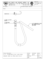
Assemble and install the Inlet Assembly, as shown in Figure 9.
1. Install the thread-to-slip fitting in the side of the Inlet Assembly. Make sure the
teflon tape is properly wrapped around the threads prior to installation. Do not
use oil-based pipe compound.
2. Locate a Hanger (item #5) on the water pipe, as shown in Figure 9.
Slide the first water pipe into the fitting. Use PVC cement to secure in place.
3. Install the Inlet Bracket, as shown in Figure 9. Use the hole in the Inlet Bracket
as a template to determine hole location in Support Channel. Use hardware
supplied to secure the Inlet Bracket to the Support Channel.
4. The Stand Tube is supplied with the Inlet Assembly.
Slide the Stand Tube Assembly down onto the Inlet Assembly, as shown in
Figure 9.
5. The inlet end components must be supported by a suspension drop line, as
shown in Figure 9.
Figure 9. Inlet End Components
Item Description Item Description
1 Regulator Hanger 6 Support Channel
2 Stand Tube Assembly 7 Water Pipe
3 Stand Tube Float 8 Threat-to-Slip Fitting
4 Inlet Bracket 9 Inlet Regulator
5 Hanger 10 Male Adapter Fitting
1186-60 7/99
1
2
3
4
5
6
7
8
9
4
10

Assembling and Hanging the Water Line Chore-Time Nipple Watering
14
MW1186E
Install Coupling Liner Assembly on the end of the water pipe, as shown in
Figure 10. Insert the pipe until it contacts the Stop Rib inside the Coupling Liner
Assembly.
Note: It may be necessary to lubricate the inside of the Coupler Liner with
soapy water to allow for easy installation.
Insert the next pipe into the other end of the Coupling Liner Assembly until it
contacts the Stop Rib inside the Coupling Liner Assembly.
Figure 10. Coupling Liner Assembly Installation
Make sure the water pipes are fully inserted into the Coupling Liner Assembly.
Note: The Support Channels will be butted against each other when the
Coupling Liner is properly installed.
Insert the Key into the first Support Channel, as shown in Figure 11. Insert the tab
of the Key through the hole in the second Support Channel. Once installed, bend the
tab to secure it in place. This will prevent the water lines from separating at the joints.
Install a Hanger, as shown in Figure 11, at each Drop Line location.
Figure 11. Securing the Water Line together
1186-61 7/99
1
2
Item Description
1 Support Channel
2 Coupling Liner Assembly
1186-62 7/99
1
2
3
Item Description
1 Support Channel
2 Coupling Liner Assembly
3Key

Chore-Time Nipple Watering Assembling and Hanging the Water Line
MW1186E
15
One Mid Line Stand Tube is required for every 150’ [46 m] of Nipple Waterer Line.
See Figure 12.
Slide a Hanger over the first side of the Tee to have the water pipe installed. Make
sure the flat flange with the hole is toward the Support Channel.
Insert the water pipe into the tee. The water pipe should be glued in the tee using PVC
cement.
Secure the Hanger to the Support Channel using the 10-24 stainless steel truss head
screw and lock nut, supplied.
Repeat this procedure on the opposite side of the Mid Line Stand Tube Kit.
Figure 12. Mid Line Stand Tube Installation
The Outlet Assembly is shipped completely assembled.
The outlet end must be located directly under a suspension drop line. This may
require adding an additional suspension drop line or cutting the last section of water
to stop directly under an existing drop line.
Install the Outlet Assembly, as shown in Figure 13. Make sure the Hanger is properly
oriented on the Outlet Assembly Tee prior to securing the water line with PVC
cement.
Secure the Hanger to the Support Channel, as shown in Figure 13. If the water line
was shortened to terminate under a suspension drop line, it may be necessary to drill
a hole in the Support Channel for the 10-24 stainless truss head screw and lock nut.
The Hanger may be used as a template to determine proper hole location.
Figure 13. Outlet Assembly Installation
1186-63 7/99
7
5
6
5
4
3
2
1
Item Description
1 Support Channel
2 Channel Support Bracket
3 Mid Line Stand Tube
4 Stainless Steel 10/24 Hardware
5 Hanger
6 Mid Line Stand Tube Tee
7 Water Pipe
1186-64 7/99
1
5
4
3
2
6
Item Description
1 Stand Tube Outlet Assembly
2 Cord Adjuster
3 Hanger
4 Support Channel
5 Hanger
6 Water Pipe

Assembling and Hanging the Water Line Chore-Time Nipple Watering
16
MW1186E
Optional Equipment: The Mid Line Shut-Off Valve may be located at any
convenient location along the water line, except next to a joint.
Determine the desired location for the Mid Line Shut-Off Valve.
Use a flat screw driver to carefully pry 3 or 4 Saddles away from the Support
Channel. This will allow easy access to the water pipe for cutting.
Use PVC pipe cutters to cut a section out of the water pipe. See Figure 14. The Shut-
Off Valve may be used as a template to determine the required size of the cut.
Apply PVC cement to the couplers on the Mid Line Shut-Off Valve Assembly.
Install the Mid Line Shut-Off Valve on the water line.
Reinstall the Saddles, previously loosened, in the Support Channel.
Note: Chore-Time recommends installing a Mid Line Stand Tube at the first
joint preceding a Mid Line Shut-Off Valve to insure proper air
removal from the water line.
Figure 14. Mid Line Shut-Off Valve Installation
1186-65 8/99
3
5
1
2
4
Item Description
1 Cut-out section of Water Pipe
2 Mid Line Shut Off Valve
3 Support Channel
4 Saddle
5Water Pipe

Chore-Time Nipple Watering Assembling and Hanging the Water Line
MW1186E
17
Optional Equipment: The Slope Compensator is used in houses that have a gradual
slope over the length of the system. The Slope Regulator allows the water pressure
to be re-adjusted along the line.
The inlet end of the Slope Compensator must be at the top of the slope. Arrow must
point in direction of waterflow. Do not attempt to push water uphill.
The maximum amount of drop between the Inlet Assembly and the Slope
Compensator, or between two Slope Compensator, or between the Slope
Compensator and the Outlet Assembly is 4 inches [100 mm]. See Figure 15.
The maximum number of Slope Compensator used on any one water line is six.
The maximum amount of slope over any water line is 28 inches [71 cm] of drop. See
Figure 15.
Figure 15. Slope Compensator Assembly Installation
1186-16 10/97
1
3
3
4
2
2
2
Item Description
1 Inlet Assembly
24" [100 mm] Max. Slope
3 Slope Compensator
4 Outlet Assembly

Filter Control Panel Installation Chore-Time Nipple Watering
18
MW1186E
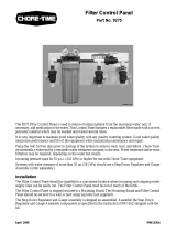
The Filter Control Panel is used to remove foreign material from the incoming water,
and, if necessary, add medication to the water.
The Step Down Regulator and Gauge Assembly is used to reduce the water pressure
supplying the Filter Control Panel. Adjust the operating pressure as recommended in
the Nipple Waterer Quick Reference Sheet. See page 31.
The Filter Control Panel and Step Down Regulator should be installed in a
convenient location where incoming and outgoing water supply lines can be easily
run. The control panel must be out of the reach of birds.
The Filter Control Panel is shipped secured to a Mounting Board. The Mounting
Board and Filter Control Panel should be secured to wall or post using lag bolts (not
supplied).
The Step Down Regulator and Gauge Assembly is shipped un-assembled. Assemble
the Step Down Regulator and Gauge Assembly components as specified in the
instruction (MW1052) shipped with the kit.
Connect the Step Down Regulator and Gauge Assembly to the Filter Control Panel,
as shown in Figure 16.
Figure 16. Control Panel Installation
Filter Control Panel Installation
Item Description
1 Part No. 35308: Step Down Regulator and Gauge Kit (shipped un-assembled)
2 Part No. 9275: Filter Control Panel (shipped assembled)
1186-66 7/99
1
2

Chore-Time Nipple Watering Flushable Filter Control Panel Installation
MW1186E
19
(optional alternative to the standard Filter Control Panel)
The Flushable Filter Control Panel is used to remove foreign material from the
incoming water, and, if necessary, add medication to the water. This Control Panel
features a filter that may be removed, cleaned, then reinstalled.
Two versions of the Filter Control Panel are available.
The low pressure version is designed to accommodate gravity flow systems with 5 -
10 p.s.i [34.5 - 69.0 kPa]. Do not exceed 15 p.s.i. [103.4 kPa] with this Control
Panel, or damage will occur to the gauges.
Systems with 11+ p.s.i. [75.8+ kPa] should use the high pressure Control Panel and
a Step Down Regulator (order separately).
The Filter Control Panel should be installed in a convenient location where incoming
and outgoing water supply lines can be easily run. The control panel must be out of
the reach of birds.
The Filter Control Panel is shipped secured to a Mounting Board. The Mounting
Board and Filter Control Panel should be secured to wall or post using lag bolts (not
supplied).
The Gauge Assembly is shipped un-assembled. Assemble the Gauge Assembly
components as specified in the instruction (MW1052) shipped with the kit.
Flushable Filter Control Panel Installation
1271-1 10/95
1271-2 10/95
Low Pressure Control Panel
Part Number 36802-1
(5-10 p.s.i.
[34.5 - 69.0 kPa]
)
High Pressure Control Panel
Part Number 36802-2
(11+ p.s.i.
[75.8+ kPa]

Anti-Roost Installation Chore-Time Nipple Watering
20
MW1186E
Pullet and breeder applications require the Anti-Roost System to be installed. This
prevents the birds from setting on the water line.
Figure 18 shows an overview of the Anti-Roost System. Notice that each length of
water line between Inlet Assemblies, Mid Line Stand Tubes, Outlet Assemblies, etc.,
are separate Anti-Roost lines connected with jumper wires.
Figure 18. Anti-Roost System Overview
1. Make certain that an Anchor Plate with Adjustment Leveler is installed at the
beginning and end of each anti-roost line. See Figure 19.
2. Install a GRAY Hanger every 30" [762 mm] on systems using 10’ [3 m]
suspension.
Install a GRAY Hanger every 32" [813 mm] on systems using 8’ [2.4 m]
suspension.
3. Beginning at the first GRAY Hanger, thread the shocker cable the full length of
the anti-roost line. Allow approximately 24" [610 mm] extra and cut the cable.
4. Create a small loop with the cable and a cable clamp.
5. Connect the cable loop to the Adjustment Leveler/Anchor Plate.
6. Install a spring on the Adjustment Leveler/Anchor Plate near the Inlet
Assembly.
7. Pull the cable taught and create a small loop with the cable and a cable clamp.
8. Connect the cable to the spring.
9. The spring should be stretched to an overall length of approximately 8"
[203 mm]. Adjust as required.
10. Repeat the above procedure on each of the anti-roost lines.
11. Use a short section of Shocker Wire to connect individual anti-roost lines at
each Mid Line Stand Tube, Air Remover, etc.
12. Secure the Poultry Trainer to a wall or post near the water line.
Chore-Time recommends wiring the Poultry Trainer into separate electrical
circuit that can be switched at the door.
Refer to the instructions supplied with the Poultry Trainer for wiring information.
Note: Make sure that the Support Channel is attached to ground (to insure proper
operation of the Poultry Trainer). See Figure 19.
Anti-Roost Installation
1186-67 9/99
/