Moxa Technologies NPort 5200 Series Quick Install Guide

Type
Quick Install Guide
P/N: 1802052000313
*1802052000313*
NPort 5200 Series
Quick Installation Guide
Edition 8.0, February 2017
Technical Support Contact Information
www.moxa.com/support
Moxa Americas:
Toll
-free: 1-888-669-2872
Tel:
1-714-528-6777
Fax:
1-714-528-6778
Moxa China (Shanghai office):
Toll
-free: 800-820-5036
Tel:
+86-21-5258-9955
Fax:
+86-21-5258-5505
Moxa Europe:
Tel:
+49-89-3 70 03 99-0
Fax:
+49-89-3 70 03 99-99
Moxa Asia-Pacific:
Tel:
+886-2-8919-1230
Fax:
+886-2-8919-1231
Moxa India:
Tel:
+91-80-4172-9088
Fax:
+91-80-4132-1045
2017 Moxa Inc. All rights reserved.
- 2 -
Overview
The NPort 5200 compact palm-sized device servers are used to control
RS-232 (NPort 5210/5230/5210-T/5230-T) or RS-422/485 (NPort
5230/5232/5232I/5230-T/5232-T/5232I-T) serial devices over a
TCP/IP-based Ethernet.
NOTE
“-T” indicates an extended operating temperature model.
Package Checklist
Before installing your NPort 5200, verify that the package contains the
following items:
1 NPort 5200 2-port Serial Device Server
Documentation & Software CD
Quick Installation Guide (printed)
Warranty card
Optional Accessories
DK-35A: DIN-Rail Mounting Kit (35 mm)
CBL-RJ45M9-150: RJ45 (8-pin) to DB9 (M) cable, 150 cm
CBL-RJ45F9-150: RJ45 (8-pin) to DB9 (F) cable, 150 cm
CBL-RJ45M25-150: RJ45 (8-pin) to DB25 (M) cable, 150 cm
CBL-RJ45F25-150: RJ45 (8-pin) to DB25 (F) cable, 150 cm
DIN-Rail Power Supply and Adapter
Note: Notify your sales representative if any of the above items are
missing or damaged.
Hardware Introduction
The NPort 5200 device servers are used to control RS-232/422/485
devices. The NPort 5210/5210-T has two 8-pin RJ45 ports, both for the
RS-232 interface. The NPort 5230/5230-T has one 10-pin terminal block,
with 5 pins used for one RS-232 port, and 5 pins used for one RS-422/485
port. The NPort 5232/5232I/5232-T/5232I-T have one 10-pin terminal
block, with 5 pins used for one RS-422/485 port, and 5 pins used for
another RS-422/485 port.
- 3 -
Reset ButtonPress the Reset button continuously for 5 sec to load
factory defaults: Use a pointed object, such as a straightened paper clip
or toothpick, to press the reset button. This will cause the Ready LED to
blink on and off. The factory defaults will be loaded once the Ready LED
stops blinking (after about 5 seconds). At this point, you should release
the reset button.
NPort 5200 LED Indicators (top panel)
LED Color
LED Function
Ready
Red
Steady on:
Power is on and the NPort 5200 is
booting up.
Blinking:
Indicates an IP conflict, or DHCP or
BOOTP server did not respond
properly.
Green
Steady on:
Power is on and the NPort 5200 is
functioning normally.
Blinking:
The device server has been located
by Administrator’s Location function
Off
Power is off, or power error condition exists.
Ethernet
Orange
10 Mbps Ethernet connection.
Green
100 Mbps Ethernet connection.
Off
Ethernet cable is disconnected, or has a short.
P1, P2
Orange
Serial port is receiving data.
Green
Serial port is transmitting data.
Off
No data is being transmitted or received through
the serial port.
- 4 -
Hardware Installation Procedure
STEP 1: After removing the NPort 5200 from the box, the first thing you
should do is connect the power adapter. Connect the 12-30 VDC power
line with the NPort 5200’s terminal block, or connect the DIN-rail power
supply with the NPort 5200’s terminal block.
STEP 2: Connect the NPort 5200 to a network. Use a standard
straight-through Ethernet cable to connect to a hub or switch. When
setting up or testing the NPort 5200, you might find it convenient to
connect directly to your computer’s Ethernet port. In this case, use a
cross-over Ethernet cable.
STEP 3: Connect the NP ort 5200’s serial port to a serial device.
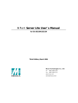
STEP 4: Placement Options
In addition to placing the
NPort 5200 on a desktop or
other horizontal surface,
you may also make use of
the DIN
-rail or wall mount
options, as illustrated here.
Wall Mount
DIN-Rail
Software Installation Information
To install NPort Administration Suite, insert the NPort Document &
Software CD into your computer’s CD-ROM drive. Once the NPort
Installation CD window opens, click on the Installation button, and then
follow the instructions on the screen. To view detailed information about
NPort 5200 Administration Suite, click on the Documents button,
and then select “NPort 5200 Series User’s Guide” to open the pdf version
of this user’s guide. The PComm Lite program is also included in the
Documentation & Software CD free of charge. Install PComm Lite to
use the Serial Console for configuring the IP address for the first time.
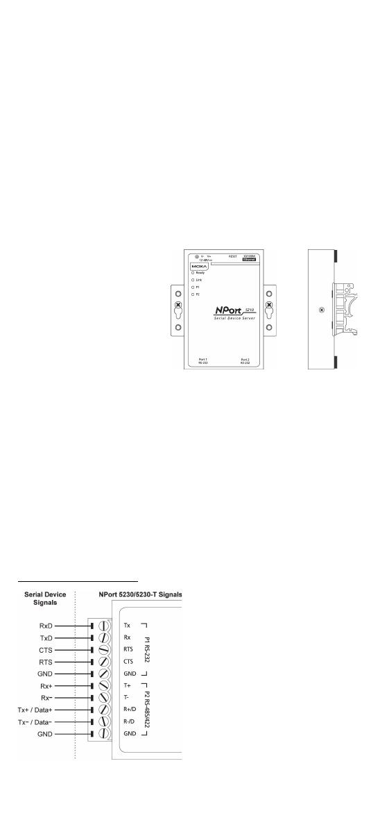
Pin Assignments and Cable Wiring
NPort 5230/5230-T
Terminal Block Wiring
- 5 -
NOTE
The NPort 5232/5232I/5232-T/5232I-T have 2 RS-422/485
ports. The pin assignments are the same as the NPort
5230/5230
-T’s port 2. Refer to the “NPort 5200 Series User’s
Manual” for more details.
Pin Assignments and Cable Wiring
NPort 5210/5210-T
RJ45 (8-pin) Connector Pinouts
8-Pin
Signal
1
DSR
2
RTS
3
GND
4
TxD
5
RxD
6
DCD
7
CTS
8
DTR
Cable Wiring (RS-232)
Four cables are available as optional accessories to connect the NPort
5210/5210-T to RS-232 serial devices. For your convenience, we show
precise cable wiring diagrams for each of the four cables.
RJ45 (8-pin) to DB25 Female (Cable Name: CBL-RJ45F25-150)
RJ45 (8-pin) to DB25 Male (Cable Name: CBL-RJ45M25-150)
- 6 -
RJ45 (8-pin) to DB9 Female (Cable Name: CBL-RJ45F9-150)
RJ45 (8-pin) to DB9 Male (Cable Name: CBL-RJ45M9-150)
Specifications
Power Requirements
NPort 5210/5210-T: 12 to 48 VDC, 325 mA at 12V (max.)
NPort 5230/5230-T: 12 to 48 VDC, 325 mA at 12V (max.)
NPort 5232/5232-T: 12 to 48 VDC, 280 mA at 12V (max.)
NPort 5232I/5232I-T: 12 to 48 VDC, 365 mA at 12V (max.)
Operating Temp.
Standard models: 0 to 55°C (32 to 131°F)
T models: -40 to 75°C (-40 to 167°F)
Operating humidity: 5 to 95% RH
Dimensions
NPort 5210/5230/5232/5210-T/5230-T/5232-T (including ears):
90 × 100.4 × 22 mm (3.54 × 3.95 × 0.87 in)
NPort 5210/5230/5232/5210-T/5230-T/5232-T (without ears):
67 × 100.4 × 22 mm (2.64 × 3.95 × 0.87 in)
NPort 5232I/5232I-T (including ears):
90 × 100.4 × 35 mm (3.54 × 3.95 ×1.37 in)
NPort 5232I/5232I-T (without ears):
67 × 100.4 × 35 mm (2.64 × 3.95 × 1.37 in)
- 7 -
Regulatory Approvals
Safety
UL 60950-1
EMC
EN 55032/24
EMI
CISPR 32, FCC Part 15B Class A
EMS IEC 61000-4-2 ESD: Contact: 4 kV; Air: 8 kV
IEC 61000-4-3 RS: 80 MHz to 1 GHz: 3 V/m
IEC 61000-4-4 EFT: Power: 1 kV; Signal: 0.5 kV
IEC 61000-4-5 Surge: Power: 1 kV
IEC 61000-4-6 CS: 150 kHz to 80 MHz: 3 V/m; Signal: 3 V/m
IEC 61000-4-8 PFMF
IEC 61000-4-11 DIPs
Marine
DNV (excluding the NPort 5210)
Medical
(NPort 5210 only) EN 60601-1-2 Class B, EN55011
  • Page 1 1
  • Page 2 2
  • Page 3 3
  • Page 4 4
  • Page 5 5
  • Page 6 6
  • Page 7 7

Moxa Technologies NPort 5200 Series Quick Install Guide

Type
Quick Install Guide

Ask a question and I''ll find the answer in the document

Finding information in a document is now easier with AI