WarmlyYours TRT120-2.7x2.7 Installation guide
- Type
- Installation guide

Free Design Service • 24/7 Installation Support •(800) 875-5285 • www.WarmlyYours.com
TempZone™
Electric Floor Heating
Shower Mat System
Installation Manual

1
How The System Works
You can feel the heat of a campre even though you are
not directly above it. Radiant energy transfer is caused by
a warm surface (the campre) giving up its heat to a cooler
surface (your body). This radiant energy travels through
space without heating the space itself. It only turns into
heat when it contacts a cooler surface. By transferring this
heat to all of the objects in the room, the heat slowly moves
to warm the air which starts to rise.
Proper Heat Dissipation
All radiant heating systems rely on a “Heat Bank”. The
heat moves from the source (Heating Element) into the
Heat Bank (thin-set) and spreads out and warms the
oor without creating an excessively hot spot. In the
WarmlyYours Floor Heating System the thin-set and/or
self-levelling cement acts as the Heat Bank. It is important
to follow the installation guidelines to create a proper Heat
Bank. For best results, we recommend a 1”- 1.5” maximum
distance between the heating cable and the top of the tile.
Wire Distances deeper than that will take longer to heat
and may not heat to expectations or satisfaction.
Securing The Mat
Once the mat is tted into the space, it needs to be secured
to the suboor to prevent movement during the installation
of the oor covering. The options for securing the mat are
discussed in detail on Page 8. Regardless of the method
you choose, it is vital that the integrity of the Heating
Element be maintained. Minimum 2 in. spacing between
adjacent heating devices.
Protecting The Heating Element
It is vital that proper care be taken to insure that the
Heating Element is not damaged during the installation of
the system or by the oor covering. A thorough preparation
and detailed inspection of the suboor will assure that any
and all objects that may damage the Heating Element are
removed prior to installation.
Never Cut The Heating Element
The key to the system is the uninterrupted ow of electricity
through the Heating Element.
nSpiration Series Control
Thermostat Options
Option 1: nSpire Touch WiFi
This programmable model features touchscreen operation,
an easy-to-use Install Wizard, and easy access to a
detailed log of its energy use. Its WiFi capability also
means that a user can operate their heating system
remotely. It can even provide the user with weather reports,
which could make leaving your house dif cult on some
winter mornings.
Option 2: nSpire Touch
Like the nSpire Touch WiFi, this programmable model also
features touchscreen operation, an easyto- use Install
Wizard, and easy access to a detailed log of its energy use.
In addition to its modern design, the nSpire Touch provides
the user with the ability to easily program their radiant
heating system to match their needs.
Option 2: nHance
This programmable model is button-operated and
represents a blend of style and usability. By giving the
user control over the programming, this model excels
at providing optimal comfort with minimal energy
consumption.
Option 2: nTrust
This non-programmable model is button-operated and is
perfect for anyone who wants a thermostat that is both
easy to install and easy to look at. It’s sleek, minimalist
appearance blends well with almost any design theme and
operating it couldn’t be simpler.
Understanding The System

System Components From
WarmlyYours
1. Heating mat (15-watt/ sq. ft.) If multiple mats are
connected to the same control device, they must be of
the same voltage type and wired in parallel.
2. nSpiration Series control device
IMPORTANT - Cross check the items you received
against the packing list and the materials list on the
installation plan to ensure that the roll length(s) and
thermostat type(s) are an exact match.
Double Check Your Dimensions
Your order consists of the exact amount of material
required to complete your project. If you have any
discrepancies or questions, call WarmlyYours at
(800) 875-5285.
Circuit Check (Not a substitute for
an OHM meter)
This device, available from WarmlyYours, is a continuity
checker that you connect to the cold lead wires before
installation of the ooring material.
Ground Fault Circuit Interrupter
GFCI or ‘GFCI-breaker’ indicating its capacity if not
incorporated into the control device you are using. This is a
built-in feature of the nSpiration Series controllers
Digital Ohm Meter (multi-meter)
Test the Heating Mat before, during, and after the
installation. A digital meter is strongly recommended
because of the precise measurements needed.
Electrical Housing Boxes/Switch
Plates
All control devices t into a single gang box. If a double
gang box is used it will need to be tted with a single gang
mud ring.
Electrical Conduit
Local electrical codes often require the power leads be
inside a metal or plastic conduit when running through
the wall from the Heating Roll to the control device. When
using an in-oor sensor, if local code requires the low
voltage sensor wire be housed in conduit, it must use a
separate conduit from the power leads(high voltage).
Utility Scissors
Scissors are the best tool to trim and alter the Fiberglass
Mesh of the Heating mesh and to separate any lengths
of Heating Element from the Mesh. Never cut the Heating
Element.
Hot Glue Gun
Use this to afx the Fiberglass Mesh portion of the Heating
Roll to the prepared suboor before covering with thin-set
cement.
Items Needed For The System Installation
2

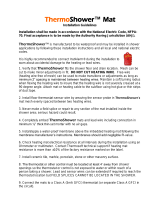
The Heating Element
The Heating Element consists of two copper alloy resistance wires
covered by Flouropolymer insulation. A braided metal surrounds
the primary Flouropolymer insulation and serves as ground sheath.
The Heating Element (A) attached with tape (C) in a serpentine
pattern to a exible Fiberglass Mesh (B). The Fiberglass Mesh is
designed to keep the Heating Element evenly spaced throughout
the roll. The cold lead return wire is factory installed at one end
of the Heating Mat and must run back to the power supply along
the perimeter of the heated space. The power lead (D) is 22-feet
in length. The lead is spliced to the Heating Element (E) at the
factory. If necessary, this lead wire may be shortened. Please
note the thickness of the factory splice and cold lead and plan
accordingly. Both the factory splices and the Heating Element must
be completely embedded in thinset or self-leveling underlayment
Floor Sensor
(not required for all systems)
Temperature sensor wire must be tested before and after installation
and must measure between 8k to 18k ohm for temperatures
between 68-86 F (20-30C). This measurement must be done with
a digital ohm meter, set to the 20k range. Beware of self-ranging
meters and analog meters.
Systems using a nSpiration Series control require a Floor Sensor
(F). This Sensor is embedded in the oor and monitors the oor
temperature. The Floor Sensor should be centered in between
2 resistance wires leaving approximately 1.5” on either side and
extend about 6” into the heated area. Avoid placing the sensor in
an area affected by a draft, a radiator or the sun. Must be installed
if using a thermostat. Some people choose to install a second
(Backup) sensor. For an additional cost you may purchase a
second sensor. NEVER run the sensor wire over, under, or next to
a heating wire. Sensor wires can touch the non-heating cold lead,
but must not run next to the lead for more than a couple of inches
and never run in the same conduit as the cold leads.
Heating Mats: Types and Sizes
Mats are rated at 15-watts per square foot and vary in size. Each
mat is designed to draw a specic amount of electricity and
therefore produce the proper amount of heat based on its size. For
this reason, the mat can never be shortened to make a proper t.
Working with the Heating Mat
The “Lead Wire” on the mat is designed to travel back to the control
device location. These wires do not heat. All connections are made
at this point.
Separating the Heating Element
from the Mesh
During the installation, you may need to separate the Heating
Element from the Fiberglass Mesh. This can be done provided
the Heating Element is not cut and the shielding is not nicked or
punctured.
E
F
G
WarmlyYours Floor Heating System.
A. Heating Element
B. Fiberglass Mesh
C. Drain Hole
D. Cold Lead Wire
E. Factory Splice
F. Floor Sensor
(optional)
G. End Cap
C/O INDIA Made by Thermopads Pvt. Ltd. for WarmlyYours.com Inc.
ENREGISTRE
LISTED
C
US
RADIANT HEATING PANEL UNIT
UNITE DE PLANCHER
CHAUFFANT ELECTRIQUE
8PA5
TempZone Electric Floor
Heating Panel
Plancher Chauffant Electrique
For installation in an
adhesive bed, self leveling or
mortar cement
Installation avec ciment, mortier
colle ou colle a carrelage
SKU S/NO
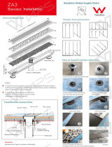
Resistance / Ohm Spez. output W/sqf
Puissance au pied carre : 15 W
Core to Core : 105.3 Ohm Voltage : 120V/60 Hz
Tension a Te nsion Length / ft
Grd Sheath to Grd Sheath : 1.02 Ohm Longueur en pieds : 9
Prise de terre a Pdt Width / ft
Largeur en pieds : 1.0
Output Unit W : 135
Puissance de l’unite
Secondary
Flouropolymer
Insulation
Primary
Flouropolymer
Insulation
Solid
Conductor
Wire
Metal Braiding
Connected to Ground
The Heating Mat
3

DO NOT SUPPLY THE SYSTEM
WITH ELECTRIC CURRENT
All testing is done with a digital Ohmmeter. Supplying the system
with a 120 volt electric current before the installation is complete
is not needed to test the system.
Taking the Ohm Readings
The electrical resistance of the Heating Roll(s) must be checked
before you start, and monitored throughout the installation
process to ensure there has been no damage causing shorts or
breaks. We recommend at least three readings be taken:
1. Before starting installation.
2. After securing the Heating Roll(s) in place on the suboor.
3. After installing the ooring surface above the Heating Roll(s).
Record the Ohm Readings
The Value on the UL label should be within +/- 15% variance of
the original measurement indicated on the label. The electrician
should carefully mark the initial Ohm reading taken onto the
warranty card. Should the initial Ohm reading be outside the 15%
+/- variance, refer to the electrical trouble shooting section on
Page 9, or call Technical Support at (800) 875-5285.
Go by the Numbers
The Ohm resistance should be measured from the inner core
of the yellow (120V) to the inner core of the Black lead wire at
the other end. Make sure that the probe of the Ohmmeter does
not touch the tinned sheath wire at either end. Even your body’s
electrical resistance can affect the reading if you touch the meter
poles. Do not hold the wires onto the probes with your ngers. A
digital meter is easier to use and strongly recommended. It is wise
to verify that the batteries of the Ohmmeter are good. Set your
Ohmmeter to measure resistance in the range of 0 to 200 Ohms.
Three (3) Ohm Readings should be taken for each roll of
WarmlyYours TempZone at each stage of the installation and
recorded in the table below.
1) Core to Core - This is the reading between the two inner
conductors on the lead wires.
2) Core to Sheath Yellow Lead - This is the reading between the
inner core and the outer ground sheath on the lead wire. This
reading should be innity.
3) Core to Sheath Black Lead - This is the reading between the
inner core and the outer ground sheath on the lead wire at the
nish point of the roll. This reading should be innity.
After the installation, if necessary, the position of a break can be
found with a troubleshooting kit and thermal camera. Repair kits
and guidance are available from the WarmlyYours support line.
Details of how to repair a damaged Heating Element are also
available on our web site at http://www.warmlyyours.com/en-US/
support.
Testing
Core to Core Core to Sheath Core to Sheath
Catalog
Number
Voltage
Usage
Refer to
Instructions
A ground fault
protection
device must
be used with
this heating
device.
Wattage
Serial
Number
4
Yellow
Ground
Ground
Yellow
Black
Black
Yellow
Ground
Ground
Yellow
Black
Black
Yellow
Ground
Ground
Yellow
Black
Black

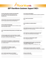
Example of Wiring a Control to Twin Conductor
Twin Conductor
Turn off Breaker
1. Attach neutral (120V) from breaker box to the terminal screw on the line side labeled “3 / L2(N)”
2. Attach line (120V) from breaker to the terminal screw on the line side labeled “2 / L1(L)”
3. Attach wire (yellow) from heating, roll to the terminal screw on the load side labeled “4”
4. Attach black wire from heating roll to the terminal screw on the load side labeled “1”
5. Using a wirenut, attach the ground wire of heating roll to the ground wire in the wallbox.
6. Turn on breaker.
ENSURE THE SYSTEM
IS GROUNDED
HOUSE GROUND
BRAIDED GROUND SHEATH
COLD LEAD
BLACK WIRE
YELLOW 120V
REAR OF THE BASE
HOT (240V) or
NEUTRAL (120V)
HOT
FROM
POWER
SOURCE
FLOOR
FRONT OF THE BASE
FLOOR SENSOR
LOAD
14
2
3
L1(L)
L2(N)
LINE
1800W/3600W MAX 15A
120/240VAC
FR
O
M
P
O
WER
S
O
UR
C
E
FL
OOR
L
O
A
D
1
4
2
3
L1
(
L
)
L2
(
N
)
LINE
1800W/3600W MAX 15
A
120/240VA
C
A B C D
out
in / sensor
r
A
B
C
D
o
u
t
in / sensor
r
Twin Conductor
1. Attach line (240V) or neutral (120V)
from breaker box to the terminal screw
on the line side labeled “3 / L2(N)”
2. Attach line (240V & 120V) from
breaker to the terminal screw on the
line side labeled “2 / L1(L)”
3. Attach red wire (yellow for 120V)
from heating, roll to the to the terminal
screw on the load side labeled “4”
4. Attach black wire from heating roll
to the terminal screw on the load side
labeled “1”
5. Using a wirenut, attach the ground
wire of heating roll to the ground wire
in the wallbox.
6. Turn on breaker.
5

Electrical Planning
The power supply to the Floor Heating System and the control device will be located at the same
point in the room and indicated on your plan. If this location has changed, call WarmlyYours to
determine if this will require a new Installation Plan. The lead wire is 15’ long. You can relocate the
control device as long as your leads reach the new location.
The thermostat requires a single gang box and should be positioned in a convenient place for easy
access. From the gang box, two sets of wires will go to the oor:
Set 1) The 120-volt or cold lead wires that power the system
Set 2) The low voltage sensor wire if a nSpiration Series control is being installed.
Some local electrical codes require the low voltage and/or 120-volt wires above the oor to be
installed in conduit. The low voltage sensor wire must not be placed in the same conduit as
the 120-volt power supply. The portion of the cold lead that is installed in the oor and all heating
wire will be directly covered with thin-set cement or ooring adhesive.
All lead wires will travel back to the control location (either directly or through a Relay Contactor)
AND MUST NOT CROSS OR COME IN CONTACT WITH THE HEATING ELEMENT.
Check the Ohms reading of the sensor wire before and after installation to make sure it has not
radically changed. Most sensor wires have Ohms readings of 8,000 to 18,000 and your OHM
meter must have a 20kohm setting for this measurement.
Prepare the Suboor
Inspect the suboor surface carefully. Remove all debris and grind any sharp edges of cracks. It is
important to remove any sharp edges or pointed objects that might damage the Heating Element.
Once installed over skim coat of thin-set or mortar type cement/adhesive material is to be installed
over the heating panel. The ooring materials that may be installed on top of the cement/adhesive
material cannot have an insulation value greater than R-1.
Careless use of tools and excessive trafc during the next few steps is the leading cause of
damage to the Heating Element. Never drop or bang a tool on the Heating Element.
Minimize walking on the Heating Elements and remember that when rising from a kneeling position,
toecaps may exert too much uneven pressure on the elements.
Make sure that everyone involved in the installation or performing other work in the space during
the installation process is aware of the extra care needed to protect the Heating Element.
Installer’s Guide
STEP 1
STEP 2
IMPORTANT
6

Installer’s Guide
Installation Recommendations
The space heating cable shall not extend beyond the room or area in which it originates.
The space heating cable is not installed in closets, over walls or partitions that extend to the ceiling, or over cabinets
whose clearance from the ceiling is less than the minimum horizontal dimension of the nearest cabinet edge that is open
to the room or area.
Isolated single runs of cable may pass over partitions where they are embedded.
The cable is not to be installed in walls.
The minimum distance between adjacent runs shall be 2 in.
Inspect and remove damaged or defective cables before they are covered or concealed.
Mark the appropriate circuit breaker reference label indicating which branch circuit supplies the circuits to those electric
space heating cables.
Minimum installation temperature for the wire is 5ºF (-15ºC). See Adhesive instructions for recommended minimum
installation temperature.
For best results, we recommend a 1”- 1.5” maximum distance between the heating cable and the top of the tile.
When Installing in Wet Locations
•. Installation shall be in accordance with the National Electric Code, NFPA-70 and CAN/CSA- C22.1, Canadian
Electric code, Part 1 (CEC) and that nal acceptance is to be made in the eld by the Authority Having Jurisdiction
(AHJ).
• WarmlyYours recommends using a separate Mat for shower areas.
Note: The UL Listing for this product covers use in wet locations for US and CANADA. Wet location installation
in United States shall be in accordance with the National Electric Code, NFPA 70 and any other applicable
jurisdictional code and nal acceptance is to be made by the Authority Having Jurisdiction (AHJ).
• If insulation board is being used over a slab, use suitable glue or cement based adhesive or thinset mortar to
adhere it to the slab. If installing in a wet location, ensure the slope of the mortar bed is maintained to direct
water to the drain pipe. Note: For wet location installaions, WarmlyYours recommends installing a secondary
waterproong membrane over the mortar bed covering the wire, as per membrane manufacturer’s instructions.
This will protect the mortar bed from any moisture that may seep through the tile, which could cause mold
problems over time.
7

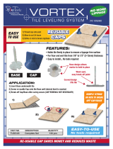
Step 1
Once the skim coat of mortar has set, dry t the TempZone™ Shower Mat to
verify its dimensions and ensure it ts the contours of the shower area.
Conduct insulation & resistance tests. Record readings on the warranty card
found inside the TempZone™ Installation instructions.
Step 2
Attach the mat to the suboor thinset using hot glue.Prepare the latex-modied
thinset. Using a at trowel, spread a coat of thinset over the installed mat.
• For best results, we recommend a 1” maximum distance between the
heating cable and the top of the tile.
• Please ensure the slope of the mortar bed is maintained to direct water
toward the shower drain.
• Allow the thinset mortar to set. Conduct resistance tests and record readings
on warranty cards.
Step 3
Using a hot glue gun, secure the cold lead to the mortar bed and over the shower
curb. In order to minimize tension on the cold lead, use an “S” formation to bring
the cold lead over the shower curb. Do not allow the tip of the hot glue gun to
touch the cold lead as it may damage the TempZone™ Shower Mat.
Direct the supply lead to the electrical panel box.
Step 4
Install a secondary waterproong membrane in accordance with the membrane
manufacturer’s installation instructions.
A secondary waterproong membrane will protect the mortar bed from any
moisture that may seep through the tile, which could cause mold problems over
time
Step 5
Install tile ooring according to the tile manufacturer’s instructions. Conduct
insulation & resistance tests and record the values on the warranty card.
Shower Mat (Bench & Floor) - Installation Guide
STEP 1
STEP 2
STEP 3
STEP 4
STEP 5
8

“Beware of Using a
Continuity Checker!”
Our smaller Heating Mats have a high
Ohm resistance and some continuity
checkers do not send enough current
to get completely through the wire and
emit the noise or light that afrms proper
continuity. If your instrument cannot
function on a small Heating Roll, please
use a digital Ohm meter.
Electrical Fault-Finding
Once the system has been turned off
and made safe, have a suitably qualied
person:
1. Ensure all wires have been connected
as per the wiring diagrams.
2. Make sure multiple rolls have been
wired in parallel with all leads returning
to the thermostat and not hooked to
each other in series.
3. Conrm that control devices are
receiving correct voltage.
Use a well calibrated digital Ohm meter
with good batteries. The Ohm resistance
level of each Heating Roll should be
checked and the reading compared with
the resistance that was recorded during
installation on the corresponding UL
label(s) (located on the circuit breaker
box) and in the log on Page 12 of this
Manual. If your reading is not within the
15%+/- range from the original reading,
the roll may be damaged in some way. If
you get zero across the core this indicates
an open or short circuit beneath the
nished ooring. The electrical contractor
must locate the point of break or short, in
coordination with the Technical Services
Department of WarmlyYours.com.
Locating a Break
or a Short
If your installation is complete, all wiring
connections have been veried to be
correct, including grounding of the system,
you have checked the sensor wire for
proper Ohms reading, and you suspect
the system is still not working; you need
to determine if there is a break or a short
under the oor.
Checking for Breaks
The Ohm resistance of each roll should be
measured across the core wires.
Make sure the probes of the Ohm meter
do not touch the sheath wire. Make sure
you do not touch either of the probe ends
with your ngers, or the meter will be
reading your internal body resistance.
Make sure your Ohm meter is set on the
proper scale (0-to- 200 for Heating Rolls,
or 0-to-20,000 for the sensor wire). Your
Ohm resistance readings should come
within 15% (plus or minus) of the original
measurement indicated by the factory on
the UL label.
If your Ohm reading is within 15% of what
it should be, there is no break. However,
you still need to check for an electrical
short.
If your Ohm reading is lower (outside the
15% range), but there is clearly some
continuity, check your Ohm meter and
your batteries. If these are good, there is a
possibility that you have several electrical
shorts.
Innity Ohm Reading?
If you have absolutely no reading (=
innity on your meter), and you are sure
you adjusted the setting of the Ohm meter
to the correct reading range (0-to-200 for
the Heating Rolls, or 0-to-20,000 for the
sensor wire), then you have a break (=
total cut) in the conductor.
Checking for
Electrical Short
In some rare occasions an installation may
have suffered from a high pressure point
that broke the insulation between the core
conductor and the multi-stranded sheath.
Such an opening in the insulation layer
can create an electrical short, even though
the Ohm reading from the white conductor
to the yellow or red conductor is normal
and does not indicate any circuit break. In
these rare occasions a continuity test will
show continuity between the one or both
of the core conductors and the sheath
wire.
There should be no continuity (=“ innite”
resistance reading, not zero) between the
conductors and the sheath.
If your instrument reveals continuity
between the core conductor and the
sheath, there is a short in the circuit.
Electrician’s Guide – Trouble Shooting
9

Important General Considerations
10
IMPORTANT INFORMATION
The most important consideration is to maintain the integrity of the Heating
Element; following these simple rules can easily do this:
1. NEVER CUT the Heating Element.
2. NEVER CUT the Heating Mat to make it shorter.
3. NEVER fold or position the Heating Element so that it overlaps itself or other
wires. The heating portion of the heating device set shall not touch, cross over,
or overlap itself. This will cause dangerous overheating.
4. NEVER run the Cold Lead Wires or Sensor Wire across the Heating Element.
5. ALWAYS make sure the system is inspected and the Ohms tested before, during
and after installation.
6. ALWAYS make sure everyone involved in the installation is aware of the care
needed to protect the Heating Element from damage.
7. ALWAYS maintain consistent spacing when positioning the Heating Element.
8. Tiles will only be warm where the heating wire is installed. If there is no heating
wire directly under the area, it will not be warm.
9. A dedicated circuit is recommended for the system.

4 2019
11
Complete the Warranty Card and return to WarmlyYours within 90 days.
Keep this installation manual safe for future reference.
Record your installation information here:
Name/Company of Electrician _____________________________________________
Address ______________________________________________________________
Tel.# _________________________________________________________________
Location of UL labels ____________________________________________________
Name/Company of Floor Installer __________________________________________
Address ______________________________________________________________
Tel.# _________________________________________________________________
Location of Installation Plan _______________________________________________
Date of installation ______________________________________________________
The instructions in this manual must be observed when installing the WarmlyYours
Floor Heating System. Failure to follow these instructions may inhibit optimal
performance of your Floor Heating System and void the system warranty. A tile-
setter, ooring contractor or qualied Do-It-Yourselfer can install the WarmlyYours
Heating Roll(s). However, a qualied electrician must complete the electrical
connections of the system to the main electrical circuit in accordance with the
National Electrical Code and your local codes. We trust that your installation goes
well and that you enjoy your warm oors!
Note for the System Installer

Warranty Information
Please complete and return the Warranty Card (online or you may
send/fax this form)
Thank you for purchasing your new WarmlyYours TempZone™ oor warming system. To register your system, go online to
www.WarmlyYours.com/warranty, or simply complete, detach and mail the Warranty Card within 30 days of date of purchase
to: WarmlyYours, 590 Telser Rd Lake Zurich, IL 60047. For your convenience, you may also fax this card to (800) 408-1100.
WarmlyYours, Inc. warrants the WarmlyYours TempZone™ electric oor warming system
rolls (“the Product”) to be free from defects in materials and workmanship for twenty ve
(25) years from the date of sale, provided that the Product is installed in accordance with
the WarmlyYours product installation guide, any special written or oral design or installation
guidelines provided by WarmlyYours for the specic project that the Product is intended, the
provisions of the National Electric Code (NEC), and all applicable local building and electrical
codes. If the Product is determined to be defective in materials and workmanship, and has
not been damaged as a result of misuse, misapplication or improper installation, WarmlyYours
will, at the customer’s discretion, either refund the original cost of the Product or reimburse the
cost for any labor and materials required to perform the repair or replacement of the Product.
Controls sold under the WarmlyYours name are warranted for specic coverage periods.
Please see www.WarmlyYours.com for the length of warranty coverage for each control.
Should the control be defective or malfunction, return the control to WarmlyYours and it will
be repaired or replaced (at WarmlyYours option). The warranty does not cover removal or
reinstallation costs. See entire warranty in packaging.
WarmlyYours Inc. assumes no responsibility under this warranty for any damage to the
Product prior to or during installation by anyone, including, but not limited to trades people or
visitors to the job site, or damage caused as a result of post installation work. Call our toll free
number, (800) 875-5285, if you have any questions about installation. The Limited Warranty is
null and void if the Product owner or his representative attempts to repair the Product without
receiving authorization. Upon notication of an actual or possible problem, WarmlyYours will
issue an Authorization to Proceed under the terms of the Limited Warranty.
Warranty Subject to the Following Conditions: 1. The warranty of the warming system must
be registered by completing and returning the attached ‘System Warranty Registration’ card
to WarmlyYours, Inc. within thirty days of date of purchase. Please keep your invoice, as
proof of date of purchase will be required in the event of a claim. 2. The warming roll must be
installed at under tile, stone, resilient ooring or laminate wood in a latex modied thinset or
a portland-based cement. 3. The warming system must be electrically grounded and protected
by a GFI (Ground Fault Interrupter). 4. The installation must comply with all national and
local electrical and building codes, as well as any other applicable statutory requirements. 5.
The manufacturer hereby reserves the right to inspect the installation site at any reasonable
time. 6. The warranty is not automatically transferred with change of ownership, but the
manufacturer may, on application, transfer the warranty for the period remaining. This transfer
is solely at the discretion of the manufacturer. 7. The warming system should be used strictly
in accordance with the following: 7.1 The voltage of the circuit should match the voltage of
the warming system, and the size of the circuit should be such that the warming system does
not occupy more than 80% of the circuit capacity. 7.2 Should you feel no warmth on the oor
within 60 minutes, verify that there is power to the control or thermostat. Contact WarmlyYours
after verifying that there is power through the load wires. Under no circumstances should
you or anyone else tamper with or attempt to repair the warming system - this will render
the warranty null and void. 7.3 Switch the warming system on and off as you would any
conventional electric heater, although timers or thermostats may be used if preferred. 7.4 Use
reasonable care in the operation of the warming system. Do not drop heavy articles on the
ooring or pierce the ooring with sharp objects. 7.5 All restrictions and warnings detailed in
the installation guide must be strictly followed.
WARMLYYOURS, INC. DISCLAIMS ANY WARRANTY NOT PROVIDED HEREIN,
INCLUDING ANY IMPLIED WARRANTY OF MERCHANTABILITY OR IMPLIED WARRANTY
OF FITNESS FOR A PARTICULAR PURPOSE. WARMLYYOURS FURTHER DISCLAIMS
ANY RESPONSIBILITY FOR SPECIAL, INDIRECT, SECONDARY, INCIDENTAL, OR
CONSEQUENTIAL DAMAGES ARISING FROM OWNERSHIP OR USE OF THIS PRODUCT,
INCLUDING INCONVENIENCE OR LOSS OF USE. THERE ARE NO WARRANTIES WHICH
EXTEND BEYOND THE FACE OF THIS DOCUMENT. NO AGENT OR REPRESENTATIVE
OF WARMLYYOURS HAS ANY AUTHORITY TO EXTEND OR MODIFY THIS WARRANTY
UNLESS SUCH EXTENSION OR MODIFICATION IS MADE IN WRITING BY A CORPORATE
OFFICER.
WarmlyYours makes no claim as to the amount of oor/room temperature rise, the time to
reach a given oor/room temperature or nal oor/room temperature due to the innumerable
variations in building construction and environmental conditions.
RETURN POLICY
Product will be accepted for return if it is in “resalable” condition. The product must be in
exactly the same condition
as when we shipped it to you.
1. HOMEOWNER INFORMATION
Company Name Phone
Address Email
City State Postal/Zip
Fax
4. HEATING SYSTEM INFORMATION
Install Date
Installed Under:
oTile oStone
oLaminate Wood oOther
(Please specify other)
_____________________________
Sub Floor Material
Set In
Total Rolls Installed
Ohm Reading Roll Size Final
Roll 1
Roll 2
Roll 3
Roll 4
Roll 5
Roll 6
Roll 7
2. FLOOR INSTALLER INFORMATION
Check here if homeowner installed
Company Name Phone
Address Email
City State Postal/Zip
Fax
3. ELECTRICIAN INFORMATION
Company Name Phone
Address Email
City State Postal/Zip
Fax

BUSINESS R EPLY MAIL
FIRST-CLASS MAIL PERMIT NO 77 LONG GROVE IL
WarmlyYours Inc
590 Telser Rd Ste B
Lake Zurich, IL 60047
NO POSTAGE
NECESSARY
IF MAILED
IN THE
UNITED STATES
POSTAGE WILL BE PAID BY ADDRESSEE
-
 1
1
-
 2
2
-
 3
3
-
 4
4
-
 5
5
-
 6
6
-
 7
7
-
 8
8
-
 9
9
-
 10
10
-
 11
11
-
 12
12
-
 13
13
-
 14
14


WarmlyYours TRT120-2.7x2.7 Installation guide
- Type
- Installation guide
Ask a question and I''ll find the answer in the document
Finding information in a document is now easier with AI
Related papers
-
WarmlyYours TRT120-1.5x09 Twin Conductor Installation Manual
-
WarmlyYours Snow Melting User guide
-
-
WarmlyYours TRT120OT-3.0x05 Installation guide
-
-
-
-
-
-
WarmlyYours TRT120-1.5x30 User manual
Other documents
-
 ThermoSoft TS3260-120 Installation guide
-
 ThermoSoft TS3230-120 Installation guide
-
 Neodrain 24-Inch Linear Shower Drain Installation guide
-
QuietWarmth QWARM3X10F120 Installation guide
-
 FloorWarm 72137 Installation guide
-
 Primo Tools TLSS120 Specification
-
Reznor EFMA Installation guide
-
 Thinset Removal Bit 6TRBSMSF User manual
-
 IdealHeat IH/AF 18-5 User guide
-
Oypla E1910 User manual


