Page is loading ...

SERVICE MANUALM
MGD Serie
s
Gas Furnaces

MGD Gas Furnace Service Manual
SEALED COMBUSTION GAS FURNACE
SERVICE MANUAL
INTRODUCTION
This manual is designed to help understand the basic fundamentals, operation, and
troubleshooting of the MGD line of gas furnaces. It was designed to be used in conjunction with
the installation manual and/or technical manuals provided with each gas furnace. This manual
covers both natural gas and L.P. gas applications.
The controls on the furnace consist of electronic components which are not user serviceable.
Therefore, it is essential that only competent, qualified, service personnel attempt to install,
service, or maintain these products.
WARNING
The information contained in this manual is intended for use by qualified
individuals who are familiar with the safety procedures required in installation and
repair and who is equipped with the proper tools and safety equipment.
Installation or repairs made by unqualified persons can result in hazards subjecting
the unqualified person making such repairs to risk of injury or electrical shock
which can be serious, or even fatal not only to them, but also to persons being
served by the equipment.
If you install or perform service on equipment, you must assume responsibility for
any bodily injury or property damage, which may result, to you or others. We will
not be responsible for any injury or property damage arising from improper
installation, service, and /or service procedures.
2 of 22

MGD Gas Furnace Service Manual
Fundamentals of the Gas Furnace
All gas furnaces consist of four main components: a burner, a heat exchanger, a blower and a
vent pipe or flue.
The burner is where the gas is delivered and burned. The gas furnace uses an electronic ignition
system and hot surface igniter instead of a constantly burning pilot light to ignite the gas.
Whenever the thermostat calls for heat, the ignition device instantly lights the burners. The hot
surface igniter is only energized when the thermostat first calls for heat and is de-energized after
ignition. By not using any gas between ignition cycles, these components conserve the fuel
previously used by a standing pilot light while providing added safety as well.
The heat exchanger transfers the heat produced from the burning gas to the home's conditioned
air distribution system and is engineered to provide maximum heat transfer to the conditioned air.
The circulation blower moves the conditioned air through ducts to the location in the home where
it is needed. This is a squirrel cage type blower powered by an electric motor, both of which have
been sized for their specific application.
The flue exhausts the gaseous byproducts of combustion to the outdoors. Venting is also
provided through the chimney. The MGD furnaces use sealed combustion systems tested and
listed for use
only with RJ – Series Roof Jack Venting System.
The MGD furnaces are set up to burn natural gas and can be converted to burn LP or propane.
ELECTRICAL SUPPLY
The unit cannot be expected to operate correctly unless it is properly connected (wired) to an
adequately sized single branch circuit. Check the Technical Data Section of this manual to
determine if the circuit is adequately sized.
WARNING
Electrical Shock hazard
Turn OFF electric power at fuse box or service panel before making any electrical
connections and ensure a proper ground connection is made before connecting
line voltage.
Failure to do so can result in property damage, personal injury and/or death.
3 of 22

MGD Gas Furnace Service Manual
SUPPLY VOLTAGE
Supply voltage to the unit should be a nominal 115 volts. It MUST be between 104 volts and 127
volts. Supply voltage to the unit should be checked WITH THE UNIT IN OPERATION. Voltage
readings outside the specified range can be expected to cause operating problems. Their cause
MUST be investigated and corrected.
ELECTRICAL GROUND
Grounding of the furnace IS REQUIRED for safety reasons.
SAFETY FEATURES
Flame sensing is attempted at all times. If a flame is sensed for 3 seconds and the thermostat W
terminal is not energized, the draft inducer and main blower are re-energized. No further
operation is allowed until flame detection is eliminated, at which point, the draft inducer performs a
post-purge and the main blower will delay off. If a flame is sensed and the W terminal is energized,
and the main valve is de-energized, the draft inducer and main blower are energized until the
flame detection is eliminated at which time normal operation may resume.
The main valve is continuously monitored. If it is energized when it should not be, the draft inducer
and main blower will be turned on. However, if during a normal ignition sequence, the air flow
proving switch has been tested to be open, draft inducer energized, NPC closes and then the
main valve is detected as being on, the ignition sequence stops and the draft inducer
ed-energized. Since the NPC is wired serially with the main valve relay, de-energizing the draft
inducer will open the NPC. If the main valve continues to be energized, then the draft inducer is
re-energized. Main valve failure with W being de-energized will result in the main blower normal
delay off being performed (once the problem has been corrected). Main valve failure during an
ignition sequence will cause a recycle to occur.
During a normal ignition sequence (if the NPC has been tested and has functioned properly) an
opening of the NPC will cause the main valve to be de-energized, the ignition cycle to be aborted,
and the proper lockout code to flash. The main blower will complete its delay off (if energized) and
the draft inducer will continue to operate until the NPC closes or the call for heat is removed.
If the high temperature limit or auxiliary limit opens without W energized, the draft inducer and
main blower will be energized immediately. This condition will persist until the limit(s) reclose at
which point an draft inducer post-purge and main blower normal delay off will be performed. If the
high temperature limit or auxiliary limit opens with W energized the ignition cycle is aborted, the
draft inducer and main blower will be energized immediately, and the failure counted toward a
maximum of 5 limit cycles in a single call for heat. If the limit cycle is not the fifth cycle then the
draft inducer and main blower will remain energized until the limit(s) re-close, at which point a
normal ignition sequence will resume. However, if the limit cycle is the fifth cycle in a single call for
heat the draft inducer and main blower will remain energized until the limit(s) re-close, at which
point the draft inducer performs a post-purge and the main blower will perform a delay off and the
control enters a one hour ignition lockout.
4 of 22

MGD Gas Furnace Service Manual
If the high temperature limit or auxiliary limit opens while the furnace is in heating mode and the
thermostat is calling for heat (W), and the switch remains open for a continuous duration of 5
minutes the control enters a fan failure lockout mode. While in this mode the control does not
allow the next ignition cycle to start until 20 minute4s after the limit recluses. Once the ignition
cycle is started the control only allows the furnace to burn for a 30 second duration, at which point
the main valve is shut off and the control starts another 20 minute ignition lockout and 30 second
burn cycle. This pattern repeats indefinitely or until the thermostat call for heat is removed, or
power to the control is removed. During this mode all other unsafe conditions (such as flame
sense, main valve energized, limit open) are still monitored and are not superseded except 5 limit
cycles does not result in a 1-hour lockout. However, any other failures do restart the lockout
interval.
The proper polarity of the AC line is tested upon power up. If the AC “hot” line is connected to L2
then a “rapid flash code” will be indicated on the LED. Normal operation will still occur; however, it
is highly improbable that flame sense will be detected. This condition will persist until power is
cycled to the board.
RECYCLES
A recycle occurs when ignition has occurred and flame failure, flame circuit failure or a main valve
failure during a call for heat is detected. If a recycle occurs before the heat fan delay ON has
completed, the delay ON is bypassed and the heat fan comes ON immediately and performs the
selected delay OFF. Up to five recycles may occur in a given operation. Following the fifth recycle
the furnace enters a one-hour lockout.
SOFTWARE TIMING TABLE
Pre-purge 30 sec.
Inter-purge 30 sec.
Igniter Warm-up Timer (1st. Pass) 30 sec.
Igniter Warm-up Timer (Retry) 30 sec.
Ignition Activation Period 5 sec.
Flame Establishing Period 2 sec.
Flame Stabilization Period 10 sec.
Flame Failure Timer (During Flame Stab.) 2 sec.
Flame Failure Response Time 0.75 sec.
Heat Fan Delay ON selectable 60, 75, 90 sec.
Heat Fan Delay OFF selectable 120, 150, 180 sec.
Cool Fan Delay OFF 18 sec.
Post-Purge 15 sec.
S/W Watchdog Timer 1.5 sec.
Ignition Lockout Timer 1 hr.
NPC Failure Timer 1 (Stuck Closed) 30 sec.
NPC Failure Timer 2 (Stuck Open) 30 sec.
NOTE: All timings given are nominal values.
5 of 22

MGD Gas Furnace Service Manual
RETRIES
A retry occurs when an attempt to achieve ignition fails and no flame is detected. The main valve
is turned off and the ignition cycle re-started. If three tries occur in a given operation sequence, the
furnace is shut down for one hour. During the one-hour period, safety conditions are still
monitored. Detection of an unsafe condition (such as flame not sensed, main valve energized,
limit open) the proper action as previously described will be followed.
CONTROL (LOW) VOLTAGE
In order to insure proper unit operation the transformer secondary output must be maintained at a
nominal 24 Volts. The 24 VAC Class 2 Transformer is protected from damage due to accidental
short circuits with a 3 AMP fuse.
GAS PIPING
Supply piping must be sized in accordance with recommendations found in National Fuel Gas
Code ANSI Z223.1/NFPA-54. In addition materials used in manufactured homes must comply
with requirements contained in HUD Title 24, Section 3280.705 as well as A119.1 and A119.2 for
recreational vehicles.
See chart in this manual for minimum sizes for NAT and LP pipe and tubing serving the furnace
only.
NOTE: The gas inlet on the gas control valve is ½” NPT. The gas line may be installed through the
bottom casing or on left or right side of furnace
.
An adequately sized gas supply to the unit is required for proper operation. Gas piping which is
undersized will not provide sufficient capacity for proper operation.
WARNING
Take care when connecting the gas line to the furnace gas valve. Use suitable wrenches
to support the gas valve when tightening fittings to prevent miss-alignment
of the attached burner orifice. Do not damage the gas valve as improper heating,
explosion, fire or asphyxiation may result.
Do not use matches, lighters, candles or other open flame to check for leaks. Use a soap
or water solution or a leak detector.
Do not pressure test the fuel system at more than 14” W.C. pressure once furnace has
been connected to the gas line. Overpressure may void the warranty and damage the
valve, which could cause an explosion, fire or asphyxiation.
6 of 22

MGD Gas Furnace Service Manual
NATURAL GAS
Inlet pressure to the unit should be checked (at the gas valve) with ALL OTHER GAS FIRED
APPLIANCES OPERATING. Inlet pressure to the unit under these conditions MUST be a
minimum of 4.5 in. W.C. If the inlet pressure is less, it may be an indication of undersized piping or
regulator problems.
L. P. GAS
Inlet pressure to the unit should be checked in the same manner as for natural gas, however, with
L.P. Gas, the inlet pressure MUST be a minimum of 11 in. W.C. If this cannot be obtained,
problems are indicated in either the regulator or pipe sizing.
Gas Pressures
Natural Gas LP Gas
Minimum
Inlet
4.5”W.C. (1120 Pa) 11”W.C. (2740 Pa)
Recommended
Inlet
7” W.C. (1740 Pa) 11” W.C. (2740 Pa)
Maximum
Inlet
13” W.C. (3230 Pa) 13” W.C. (3230 Pa)
Manifold
Pressure
3.5” W.C. (870 Pa) 10” W.C. (2490 Pa)
CHECKING INPUT (FIRING) RATE
Once it has been determined that the gas supply (inlet) pressure is correct to the unit, it is
necessary to check the input (firing) rate. This can be done in two ways. The preferred method is
to check and adjust (as necessary) the manifold pressure. The second way is to “Clock” the gas
meter (on Natural Gas Models).
CHECKING MANIFOLD PRESSURE
GAS PRESSURE TESTING DEVICES
7 of 22

MGD Gas Furnace Service Manual
1. Connect a U-tube manometer or Magnehelic gauge (0-12 in. W.C. range) to the pressure tap
on the OUTLET side of the gas valve.
2. Turn gas ON and fire unit.
3. Manifold pressure should be set to 3.5 in. W.C. for Natural Gas, and to 10 in. W.C. for L.P.
Gas.
4. This valve is not field adjustable.
5. For units above 2,000 Ft., insure that orifice size has been changed (per National Fuel Gas
Code
- Appendix “F”) if gas supply has not already been de-rated for altitude by the gas
supplier.
WARNING
Fire or explosion hazard.
Turn OFF gas at shut off before connecting U-tube Manometer or Magnehelic.
Failure to turn OFF gas at shut OFF before connecting Manometer or Magnehelic
can result in personal injury and/or death.
“CLOCKING” GAS METER (NATURAL GAS)
1. Check with gas supplier to obtain ACTUAL BTU content of gas.
2. Turn OFF gas supply to ALL other gas appliances.
3. Time how many seconds it takes the smallest (normally 1 cfh) dial on the gas meter to make
one complete revolution.
EXAMPLE
Natural Gas No. of Seconds Time Per Cubic BTU's Per
BTU Content Per Hour Foot In Seconds Hour
1000 3,600 48 75,000
1,000 * 3,600 / 48 = 75,000 BTUH
4. Calculate input rate by using ACTUAL BTU content of gas in formula shown in example.
8 of 22

MGD Gas Furnace Service Manual
CHECKING TEMPERATURE RISE
The unit is designed to operate within a certain specified range of temperature rise. See unit
rating plate for allowable range.
Operating the unit outside the specified range may result in lower efficiency and/or comfort levels,
as well as premature combustion component failures.
The temperature rise through the unit is the difference in temperature between the return air, and
the supply air.
NOTE: BEFORE CHECKING TEMPERATURE RISE BE CERTAIN THAT MANIFOLD
PRESSURE IS PROPERLY ADJUSTED
Temperature Rise can be checked by placing a thermometer in the return air duct as close to the
unit as possible. Place a second thermometer in the supply duct at least two (2) feet away from
the unit. This will prevent any false readings caused by radiation from the unit heat exchanger.
Make sure that the FILTER IS CLEAN and that ALL REGISTERS AND/OR DAMPERS ARE
OPEN.
Operate the unit for 15 minutes before taking temperature readings. Subtract the return air
temperature from the supply air temperature. The result is the temperature rise. Compare with the
allowable rise listed for the model (size) you are checking.
If the rise is not within the specified range, it will be necessary to change the heating blower
speed. If the
rise is too high, it will be necessary to increase the blower speed. If the
rise is too low, it will be necessary to reduce the blower speed.
HIGH ALTITUDE OPERATION
This series of unit is designed to operate in the majority of the country without any modifications.
Beginning at altitudes of 2,000 Ft. above sea level, certain measures need to be taken to insure
continued, safe, reliable operation. For example, units must be de-rated for altitude (by changing
orifice size) based upon the Btu content of the gas being supplied and installed altitude.
When servicing a unit installed at altitudes above 2,000 Ft., insure that it has been properly
modified to operate at that particular altitude. Check with the gas supplier to determine if the gas
being supplied has already been de-rated for altitude. If not, check the unit Installation and
Operatins Manual for a listing of orifice sizes to be used with “standard” 1000 Btu per cubic foot
Natural gas at higher altitudes.
ROOM THERMOSTATS
Room thermostats are available from several different manufacturers in a wide variety of styles.
They range from the
very simple and inexpensive Bi—metallic type to the complex and costly
electronic set—back type. In all cases, no matter how simple or complex, they are simply a switch
(or series of switches) designed to turn equipment (or components) ON or OFF at the desired
conditions.
9 of 22

MGD Gas Furnace Service Manual
An improperly operating, or poorly located room thermostat can be the source of perceived
equipment problems. A careful check of the thermostat and wiring must be made then to insure
that it is not the source of problems.
LOCATION
The thermostat should not be mounted where it may be affected by drafts, discharge air from
registers (hot or cold), or heat radiated from the sun or appliances.
The thermostat should be located about 5 Ft. above the floor in an area of average temperature,
with good air circulation. Normally, an area in close proximity to the return air grille is the best
choice.
Mercury bulb type thermostats MUST be level to control temperature accurately to the desired
set—point. Electronic digital type thermostats SHOULD be level for aesthetics.
THERMOSTAT LOCATION
HEAT ANTICIPATORS
Heat anticipators are small resistance heaters built into most electro—mechanical thermostats.
Their purpose is to prevent wide swings in room temperature during furnace operation.
In order to accomplish this, the heat output from the anticipator must
be the same regardless of
the thermostat used. Consequently, most thermostats have an adjustment to compensate for
varying current draw in the thermostat circuit.
The proper setting of heat anticipators then is important to insure proper temperature control and
customer satisfaction.
10 of 22

MGD Gas Furnace Service Manual
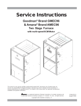
Measuring Current Draw
The best method to obtain the required setting for the heat anticipator is to measure the actual
current draw in the control circuit (“W”) using a low range (0—2.0 Amps) Ammeter. (See
Illustration) After measuring the current draw, simply set the heat anticipator to match that value. If
a low range ammeter is not available, a “Clamp—on” type ammeter may be used as follows:
1. Wrap EXACTLY ten (10) turns of wire around the jaws of a clamp--on type ammeter.
2. Connect one end of the wire to the ‘W’ terminal of the thermostat sub—base, and the other to
the “R” terminal.
3. Turn power on, and wait approximately 1 minute, then read meter.
4. Divide meter reading by 10 to obtain correct anticipator setting.
Electronic thermostats do not use a resistance type anticipator. These thermostats use a
Microprocessor that determines a cycle rate based on a program loaded into it at the factory.
Cycle rates are normally field adjustable for different types of equipment. The method of
adjustment, varies from one thermostat manufacturer to another. Check with the thermostat
manufacturer to find out the proper way of adjusting the cycle rate.
CONTROL WIRING
Control wiring is an important part of the total equipment installation, since it provides the vital
communications link between the thermostat, and the equipment. It is often overlooked as the
source of equipment malfunctions. Control wiring that is either too long, undersized, or improperly
connected (be it simply loose, or on the wrong terminal) can in fact be the source of many
equipment problems.
ALWAYS check to make sure that the control wiring is connected to the proper terminal(s) of the
equipment and thermostat you are using. Remember
different thermostat manufacturers do not
always identify thermostat terminals alike. Connections MUST be clean and tight to insure
trouble—free operation.
On the MGD models, the COOLING fan speed is energized via the Y terminal. The HEATING
speed will be energized via the W terminal.
11 of 22

MGD Gas Furnace Service Manual
DIAGNOSTIC FEATURES
This section describes the diagnostic features incorporated into the control. The furnace
electronic controls utilize an on-board LED to transmit a diagnostic flash code, which may be used
in troubleshooting system problems. The table below describes these codes.
Table of Diagnostic Codes
FLASHES FAULT CONDITION CHECK
STEADY ON NORMAL OPERATION
1 IGNITION FAILURE (ONE HOUR LOCKOUT) GAS FLOW, GAS PRESSURE, GAS VALVE, FLAME SENSOR
2 CLOSED PRESSURE SWITCH PRESSURE SWITCH STUCK CLOSED
3 PRESSURE SWITCH FAILED TO CLOSE VENTER, PRESSURE SWITCH, VENT BLOCKAGE
4 LIMIT SWITCH OPEN MAIN LIMIT, AUX. LIMIT
5 GAS VALVE ENERGIZED WITH (W) OFF GAS VALVE
RAPID FLASH INCORRECT LINE VOLTAGE PHASING L1 AND L2 CONNECTIONS REVERSED
LIMIT SWITCHES
Two different kinds of limit switches are used on the MGD series of gas furnaces. They are the
main limit (manual re-set) and the auxiliary limit (automatic re-set) and are used on ALL models.
Typical Limit Switch
It must be remembered, that a limit switch is a safety device and other than for testing purposes,
limit switches should never be jumped out Limit switches are normally closed electrical
switches that are designed to open when their pre-determined limit setting has been reached. It
should also be remembered, that when a limit switch opens, it more than likely is not due to a bad
switch!
The cause of the opening limit must be found and corrected, before the furnace can resume
proper operation.
12 of 22

MGD Gas Furnace Service Manual
WARNING
Fire hazard.
Limit controls are factory preset and MUST NOT be adjusted. Use ONLY
manufacturer’s authorized replacement parts.
Failure to do so can result in personal injury and/or death.
MAIN LIMIT SWITCH - 180°F MANUAL RESET
A Normally Closed switch located on the blower deck of the unit. Its purpose is to monitor supply
air temperature, and to interrupt burner operation when a supply air temperature is sensed which
would result in the furnace exceeding maximum allowable outlet air temperature. While the main
limit is open, the combustion blower, and/or the circulating blower will be energized continuously.
This control is a manual re-set control, which must be re-set manually when the temperature
sensed drops to a safe level.
If this limit switch trips during furnace operation, it is more than likely due to a high temperature
rise through the furnace. See checking temperature rise section in this manual.
High temperature rise can be caused by either OVER-FIRING (high manifold pressure, incorrect
orifices, etc.) or LOW AIR FLOW (dirty filter, blower speed too low, excessive static in duct
system, etc.)
To verify this, the cut-out temperature of the switch should be checked using a thermocouple type
thermometer connected to the switch as follows:
1. Operate furnace for several minutes.
2. Block return air grille(s) to furnace.
3. Observe temperature at which switch opens and burner operation ceases.
4. Remove blockage from return grille(s).
5. Observe temperature at which switch closes and burner operation resumes.
6. Compare readings with the limit setting listed in the Tech. Service Data section for the model
you are servicing.
If switch is opening within the specified range, then it is simply doing its job, and the cause of the
over—temperature must be determined and corrected.
13 of 22

MGD Gas Furnace Service Manual
If, however, the switch is found to be opening prematurely, then it should be replaced. When
replacing ANY limit switch, use ONLY a switch of EXACTLY the same temperature setting. Use of
a different temperature limit switch can create a dangerous situation. Be certain you have the
correct control part when replacing the limit switch.
AUXILLIARY LIMIT SWITCH - 140°F AUTO RESET
This limit switch is located inside the control box and automatically re-sets itself after the
temperature of the switch has dropped below the factory set point. This switch is normally closed
and operates much like the main limit switch. This switch can be tested using the same procedure
as described in the main limit switch section of this manual.
When replacing, use only exact replacement parts with the same temperature setting. Use of a
different temperature limit switch can create a dangerous situation.
PRESSURE SWITCHES
An air-proving pressure switch is used on all models to insure that a draft has been established
through the heat exchanger before allowing burner operation.
All Models use a dual port switch which senses the pressure differential that is created by the
combustion blower.
All Models use the same setting Normally Open pressure switch. The particular setting is
required to insure continued SAFE, RELIABLE, operation. NEVER SUBSTITUTE a pressure
switch with one that is similar in appearance. ONLY FACTORY PROVIDED or AUTHORIZED
SUBSTITUTES ARE ACCEPTABLE.
If you are servicing a unit whose pressure switch will not close, or remain closed during operation,
the operating pressure of that unit should be checked and compared to the switch setting.
Under normal operating conditions, sufficient negative pressure will be created to close the
pressure switch, and keep it closed to keep the furnace section operating. Under abnormal
conditions, however, such as a restricted vent (flue exhaust hood), or a leak in the heat
exchanger, sufficient negative pressure will not be created. This will result in the switch failing to
closed or failing to remain closed during furnace section operation.
COMBUSTION AIR BLOWER
All models use the same combustion air mounted on the inlet side of the heat exchanger. The
purpose of the combustion blower is to establish a draft (flow) through the heat exchanger, to
insure that all flue products are carried outside the unit via the flue exhaust hood.
There is a pressure tap on the induced draft blower housing, and one on the burner box, which
connect via a silicone rubber tube to the taps on the unit’s pressure switch. During normal
operation the exhaust blower develops a sufficient differential pressure to close the pressure
switch and keep it closed.
14 of 22

MGD Gas Furnace Service Manual
A 115-volt motor drives the exhaust blower. Basically there are only two problems that can be
experienced with this component. It can have a motor failure, or it can become noisy due to bad
bearings, loose blades, etc.
When servicing the blower be certain to insure that gaskets and sealing material are replaced.
Leaks can cause operational problems, such as the pressure switch not closing.
CAPACITORS
A permanent split capacitor is used for the circulating blower fan motor. Before replacing a motor,
the condition of the capacitor should be verified, since it, and not the motor may be the source of
the problem.
Before checking the capacitor, the supply power to the unit should be turned OFF.
The capacitor should then be discharged through a resistor before testing. A 20,000 Ohm 2 Watt
resistor can be used for this purpose.
The condition of the capacitor should be verified with a capacitor analyzer, one that indicates the
capacitor’s value in microfarads, rather than with an Ohmmeter. The reason for this is that an
Ohmmeter test can only indicate if a capacitor is OPEN, or SHORTED. It cannot verify if its
value (microfarads) is within an acceptable range.
Capacitor should test to within 10% of its rated value. Capacitors testing outside this range should
be replaced. A weak capacitor can be the cause of a motor failing to start, or failing to run at
proper speed.
Checking Capacitor
BLOWER ASSEMBLY
All models use a multi-speed, permanent split capacitor motor, direct-drive, blower assembly.
Different size (HP) motors and/or different diameter blower wheels are used in each model to
obtain the required airflow. The method for accessing and removing the blower motor/assembly
for servicing is described below.
15 of 22

MGD Gas Furnace Service Manual
Blower Assembly removal and replacement
1. Disconnect electrical power to the furnace.
2. Remove the blower access panel.
3. Unplug blower-wiring harness from plug in top of control box.
4. Remove the four screws securing the blower housing.
5. Slide entire housing to the left to disengage the tabs holding the right side.
6. Pull back on top of blower and lift bottom to disengage the two tabs on the bottom side.
7. Lift blower assembly out of furnace cabinet.
8. Installation is the reverse of these removal steps.
Blower wheel inspection
Visually inspect the blower wheel for accumulations of dirt or lint which will reduce airflow. Clean
the blower wheel of any accumulations.
BLOWER SPEEDS
The wide variety of applications and installations of furnaces throughout the country makes it
impossible to factory select blower speeds that will provide proper operation for all installations.
The blower speeds for both heating and cooling must be field selected for each particular
installation to insure proper operation.
The criteria for selecting the proper blower speeds IS NOT High for cooling, Low for heating. That
may be how it works out SOMETIMES but it can be exactly the opposite.
The PROPER CRITERIA FOR SELECTING BLOWER SPEEDS is as follows:
A blower speed must be selected that will provide proper temperature rise through the furnace.
See Checking Temperature Rise found elsewhere in this manual. The required CFM for a
particular temperature rise can also be calculated by using the following formula:
Output BTU
Temp. Rise X 1.08 = CFM
EXAMPLE: A model MGD75-E3A has an output of 60,000 Btuh. A temperature rise of 60°F
(range of 45-75°F allowable) is desired. Measured external static pressure is 0.3” W.C. with a
dry
coil.
60,000 or 60,000 = 926 CFM
60 X 1.08 64.8
16 of 22

MGD Gas Furnace Service Manual
Checking the blower performance data for this model, (see chart below) indicates that at 0.3”
W.C., low speed will deliver 910 CFM to a system that has no coil installed. Accordingly, low
speed should be used in this example for the HEATING speed. If a coil is installed however, the
chart indicates that 865 CFM will be delivered on low speed and 1030 on MED speed.
BLOWER PREFORMANCE DATA - MGD FURNACE
ESP, IN. W.C. DUCT 0.1 0.2 0.3 0.4 0.5
A3/12 BLOWER - 10 X 8, 1/3 HP, 3 SP (Accessory P/N: 87-1008-3/12A1
CFM - NO COIL LOW 980 950 910 875 825
" MED 1220 1170 1120 1065 1015
" HIGH 1460 1400 1340 1270 1195
CFM - WITH COIL LOW 945 905 865 815 775
" MED 1130 1085 1030 970 905
" HIGH 1300 1240 1180 1105 1035
BLOWER - 10 X 8, 3/4 HP, 4 SP (Accessory P/N: 87-1008-4/16A1
CFM - NO COIL LOW 995 960 915 875 825
" MED 1205 1165 1130 1090 1045
" MED HIGH 1470 1425 1385 1345 1310
" HIGH 1810 1765 1720 1680 1635
CFM - WITH COIL LOW 950 905 865 835 790
" MED 1145 1115 1080 1035 1000
" MED HIGH 1375 1345 1315 1280 1245
" HIGH 1700 1660 1620 1575 1540
SELECTING BLOWER SPEEDS
After determining necessary CFM and speed tap data, refer to the unit wiring diagram for the
correct speed tap.
BURNERS
Burners used in this series are of the INSHOT type. Their operation can be compared to that of a
torch since they produce a hard, sharp, flame. Proper adjustment of the manifold gas pressure is
essential, to insure that the burners are operating properly.
The burners used in this series ARE NOT EQUIPPED WITH AIR SHUTTERS, as none are
required. Proper operation is obtained by insuring that the orifice size and manifold pressure are
correct for the fuel being used and the altitude of the installation.
PILOT ADJUSTMENT (All Models)
Pilot flame adjustment is the same for all models, regardless of which ignition system is used. The
pilot flame should be adjusted to envelop flame sensor. Turn pilot adjustment screw
COUNTERCLOCKWISE (out) to INCREASE and CLOCKWISE (in) to DECREASE.
17 of 22

MGD Gas Furnace Service Manual
BURNER/HEAT EXCHANGER INSPECTION & CLEANING
Check the exterior and the interior flue gas passages of the heat exchanger for any evidence of
deterioration due to corrosion, cracking or other causes. If signs of scaling or sooting exist,
remove the burners and clean the heat exchanger as required.
Note: Under normal operating circumstances, the heat exchanger should NOT require cleaning.
If a unit requires cleaning, it indicates that there are likely operational problems such as low gas
pressure, etc. which may cause sooting. The cause of such improper operation MUST be
determined and corrected to insure continued safe, reliable operation.
INSPECTION AND CLEANING OF BURNER
ASSEMBLY AND HEAT EXCHANGER
Inspecting the burners and heat exchanger tubes requires the use of a light and small mirror on an
extension handle.
I. Disconnect all electrical power to unit.
2. Turn gas OFF at manual shut off valve.
3. Disconnect gas pipe at union.
4. Disconnect wires from gas valve, note connections.
5. Remove screws securing the burner box cover and remove the cover, gas valve, and burner
assembly as one unit.
6. Clean burner assembly with a stiff brush.
Note: The burner assembly is equipped with a hot surface igniter. Use extreme caution not
to damage it. This igniter is usually made of a ceramic type material, which is VERY brittle,
and breaks easily.
7. Clean interior of heat exchanger including flue gas passages by using small brushes and a
vacuum cleaner. It may be necessary to fabricate handle extensions for the brushes to reach
the areas that require cleaning. Re-inspect after cleaning and replace the heat exchanger if
defective.
8. Reinstall parts and gaskets in reverse order. Any gaskets damaged during disassembly
MUST be replaced with new gaskets.
9. Turn gas
ON and check for leaks. Any leaks found MUST be repaired immediately.
10. Install all access panels, turn electrical power on and check furnace for normal operation.
18 of 22

MGD Gas Furnace Service Manual
HEAT EXCHANGER REMOVAL/REPLACEMENT
Removal of the heat exchanger from the unit is only required if the heat exchanger has failed. The
causes of heat exchanger failures are normally NOT due to defects in material and workmanship
in the heat exchanger itself.
Before replacing any heat exchanger, the cause of its failure must be determined and corrected.
Failure to do so will cause the replacement heat exchanger to also fail for the same reasons.
Some possible causes of heat exchanger failure are as follows:
1. Temperature rise too high, causing heat exchanger to exceed design-operating
temperature. Operating outside allowable temperature rise range will eventually cause
cracks to appear in the heat exchanger. Filter may be dirty, registers may be closed off,
blower speed may be too low, or unit may be over—fired as a result of manifold pressure
being too high or incorrect orifice being used.
2. Temperature rise too low, causing heat exchanger to never achieve design-operating
temperature. Operating outside allowable temperature rise range can allow condensation
to form inside the heat exchanger, eventually causing corrosion to appear in the heat
exchanger. Blower speed may be too high, return air duct may be open and leak ambient
air or unit may be under—fired as a result of manifold pressure being too low or incorrect
orifice being used.
DIAGNOSTIC
FEATURES
This section will describe the diagnostic features incorporated into the control. The furnace
electronic controls utilize an on-board LED to transmit a diagnostic flash code, which may be used
in troubleshooting system problems. The table below describes these codes.
Table of Diagnostic Codes
FLASHES FAULT CONDITION CHECK
STEADY ON NORMAL OPERATION
1 IGNITION FAILURE (ONE HOUR LOCKOUT) GAS FLOW, GAS PRESSURE, GAS VALVE, FLAME SENSOR
2 CLOSED PRESSURE SWITCH PRESSURE SWITCH STUCK CLOSED
3 PRESSURE SWITCH FAILED TO CLOSE VENTER, PRESSURE SWITCH, VENT BLOCKAGE
4 LIMIT SWITCH OPEN MAIN LIMIT, AUX. LIMIT
5 GAS VALVE ENERGIZED WITH (W) OFF GAS VALVE
RAPID FLASH INCORRECT LINE VOLTAGE PHASING L1 AND L2 CONNECTIONS REVERSED
19 of 22

MGD Gas Furnace Service Manual
PRESSURE CONTROL LOCKOUT
Pressure control lockout happens when the differential pressure switch fails to operate properly
during a call for heat. If the pressure switch is continuously closed, even with the draft inducer off,
no further operation of the furnace will occur, except if flame is detected, main valve is detected, or
if the limit opens. If the condition persists for 30 seconds, the control will flash lockout code 3 until
the condition is corrected or the call for heat is removed. If the differential pressure switch will not
close after the draft inducer has been energized for 30 seconds, the control will begin to flash
lockout code 3 until the condition is corrected or the call for heat is
removed. If the differential
pressure switch has operated properly but opens during normal operation with W energized, the
main valve is de-energized immediately and lockout code 3 will flash. If the differential pressure
switch re-closes, normal operation will return but the differential pressure switch failure will be
counted as a recycle. If the differential pressure switch does not re-close, the control will continue
to flash the lockout code until it does close or the call for heat is removed.
FLAME SENSOR INPUTS
The flame sensor input is capable of reliably detecting the presence of a flame through the use of
the flame Rectification Principle. In order to achieve this, the circuit must properly sense a flame or
its absence whenever the AC Line voltage (between L1 and L2) is at 90 Vrms, and flame
rectification current built into the system is recognized. This allows the verification of the circuits
operation if a flame is detected.
ONE HOUR LOCKOUT
A one-hour lockout occurs following: three retries, five recycles, and five limit cycles in a single call
for heat. During the one-hour lockout, flame detection, limit conditions, and main valve are tested.
Any improper results will cause the appropriate action to occur. While in the one-hour lockout, the
cooling operation of the furnace will continue to function fully. Removing the call for heat will reset
the one-hour lockout period.
20 of 22
/