Page is loading ...

RS6612013
August 2014
This manual is to be used by qualified, professionally trained HVAC technicians only. Goodman does not
assume any responsibility for property damage or personal injury due to improper service procedures or
services performed by an unqualified person. The material in this manual does not supercede manufacturers
installation and operation instructions.
Copyright© 2014 Goodman Company, L.P.
Service Instructions
Goodman
®
Brand GMEC96
& Amana
®
Brand AMEC96
Two Stage Furnace
with multi-speed ECM Motor
®
is a registered trademark of Maytag Corporation or its related companies and
is used under license to Goodman Company, L.P., Houston, TX, USA. All rights reserved.

2
IMPORTANT INFORMATION
Pride and workmanship go into every product to provide our customers with quality products. It is possible, however,
that during its lifetime a product may require service. Products should be serviced only by a qualified service technician
who is familiar with the safety procedures required in the repair and who is equipped with the proper tools, parts, testing
instruments and the appropriate service manual. REVIEW ALL SERVICE INFORMATION IN THE APPROPRIATE
SERVICE MANUAL BEFORE BEGINNING REPAIRS.
IMPORTANT NOTICES FOR CONSUMERS AND SERVICERS
RECOGNIZE SAFETY SYMBOLS, WORDS AND LABELS
TABLE OF CONTENTS
WARNING
HIGH VOLTAGE
D
ISCONNECT ALL POWER BEFORE SERVICING OR
INSTALLING THIS UNIT.
MULTIPLE POWER SOURCES MAY
BE PRESENT.
FAILURE TO DO SO MAY CAUSE PROPERTY
DAMAGE, PERSONAL INJURY OR DEATH.
G
OODMAN
WILL
NOT
BE
RESPONSIBLE
FOR
ANY
INJURY
OR
PROPERTY
DAMAGE
ARISING
FROM
IMPROPER
SERVICE
OR
SERVICE
PROCEDURES
. I
F
YOU
INSTALL
OR
PERFORM
SERVICE
ON
THIS
UNIT
,
YOU
ASSUME
RESPONSIBILITY
FOR
ANY
PERSONAL
INJURY
OR
PROPERTY
DAMAGE
WHICH
MAY
RESULT
. M
ANY
JURISDICTIONS
REQUIRE
A
LICENSE
TO
INSTALL
OR
SERVICE
HEATING
AND
AIR
CONDITIONING
EQUIPMENT
.
T
O
PREVENT
THE
RISK
OF
PROPERTY
DAMAGE
,
PERSONAL
INJURY
,
OR
DEATH
,
DO
NOT
STORE
COMBUSTIBLE
MATERIALS
OR
USE
GASOLINE
OR
OTHER
FLAMMABLE
LIQUIDS
OR
VAPORS
IN
THE
VICINITY
OF
THIS
APPLIANCE
.
IMPORTANT INFORMATION ......................... 2 - 6
PRODUCT IDENTIFICATION ........................ 7 - 8
INSTALLATION CONSIDERATIONS ........... 9 - 26
SYSTEM OPERATION ...............................27 - 33
ACCESSORIES..........................................34 - 37
SERVICING TABLE OF COnTENTS.................38
SERVICING ................................................ 39 - 56
MAINTENANCE ............................................57- 58

3
IMPORTANT INFORMATION
To locate an authorized servicer, please consult your telephone book or the dealer from whom you purchased this
product. For further assistance, please contact:
CONSUMER INFORMATION LINE
GOODMAN
®
BRAND PRODUCTS
TOLL FREE
1-877-254-4729 (U.S. only)
email us at:
fax us at: (731) 856-1821
(Not a technical assistance line for dealers.)
CONSUMER INFORMATION LINE
AMANA
®
BRAND PRODUCTS
TOLL FREE
1-877-254-4729 (U.S. only)
email us at:
hac.consumer[email protected]
fax us at: (731) 856-1821
(Not a technical assistance line for dealers.)
Outside the U.S., call 1-713-861-2500.
(Not a technical assistance line for dealers.) Your telephone company will bill you for the call.
DANGER
0140M00020-D
CARBON MONOXIDE POISONING HAZARD
Special warning for installation of furnaces or air handling units in enclosed area such as garages, utility rooms or parking areas. Carbon monoxide producing
devices (such as automobile, space heater, gas water heater, etc.) Should not be operated in enclosed areas such as unventilated garages or utility rooms because
of the danger of carbon monoxide (CO) poisoning resulting from the exhaust emissions. If a furnace or air handler is installed in an enclosed area and a carbon
monoxide producing device is operated therein, there must be adequate direct outside ventilation. Carbon monoxide emissions can be (re)circulated throughout
the structure if the furnace or air handler is operating in any mode. CO can cause serious illness including permanent brain damage or death.
A
vertissement special au sujet de l'installation d'appareils de chauffage ou de traitement d'air dans des endroits clos, tets les garages, les locaux d'entretien et les
RISQUE D'EMPOISONNEMENT AU MONOXYDE DE CARBONE
stationnements. Evitez de mettre en marche les appareils produisant du monoxyde de carbone (tels que les automobile, les appareils de chauffage autonome,etc.)
dans des endroits non ventilés tels que les d'empoisonnement au monoxyde de carbone. Si vous devez faire fonctionner ces appareils dans un endroit clos,
assures-vous qu'il y ait une ventilation directe provenant de l'exterie . Les émissions de monoxyde de carbone peuvent etre recircules dans les endroits clos,
si l'appareil de chauffage ou de traitement d'air sont en marche. Le monoxyde de carbone peut causer des maladies graves telles que des dommages permanents
au cerveau et meme la mort.
Advertencia especial para la instalación de calentadores ó maneja oras de aire en áreas cerradas como estacionamientos ó cuartos de servicio. Los equipos ó
RIESGO DE INTOXICACIÓN POR MONÓXIDO DE CARBONO
aparatos que producen monóxido de carbono (tal como automóvil, calentador de gas, calentador de agua por medio de gas, etc) no deben ser operados en
áreas cerradas debido al riesgo de envenenamiento por monóxido de carbono (CO) que resulta de las emisiones de gases de combustión. Si el equipo ó
aparato se opera en dichas áreas, debe existir una adecuada ventilac ón directa al exterior. Las emisiones de monóxido de carbono pueden circular a través
del aparato cuando se opera en cualquier modo. El monóxido de carbono puede causar enfermedades severas como daño cerebral permanente ó muerte.
DANGER
PELIGRO

4
gas. If you then smell gas, STOP!above on this label.
Follow "B" in the safety information
above on this label. If you don't smell
8. Move the gas control switch or knob
9. Replace control access panel.
gas, go to the next step.
technician or gas supplier.
11. Set the thermostat to the desired
12. If the appliance will not operate,
To Appliance" and call your service
5. Replace control access panel.
to "OFF". Do not force.
follow the instructions "To Turn Off Gas
4. Move the gas control switch or knob
Do not store or use gasoline or
other flammable vapors and liquids in the vicinity of this
TO TURN OFF GAS TO APPLIANCE
10. Turn on all electric power to the
FOR YOUR SAFETY
or any other appliance.
2. Turn off all electric power to the
appliance if service is to be performed.
1. Set the thermostat to its lowest setting.
3. Remove control access panel.
automatic ignition system which
4. This appliance is equipped with an
3. Turn off all electric power to the
2. Set the thermostat to lowest setting.
5. Remove control access panel.
try to light the burners by hand.
6. Move the gas control switch or knob
automatically lights the burners. Do not
to "OFF".
appliance.
setting.
appliance.
to "ON".
0140F00001P
SWITCH SHOWN
IN "ON" POSITION
GAS CONTROL
Force or attempted repair may result in
FOR YOUR SAFETY READ BEFORE OPERATING
call the fire department.
damage, personal injury or loss of life.
If you cannot reach your gas supplier,
a fire or explosion may result causing property
If you do not follow these instructions exactly,
which has been under water.
C. Use only your hand to move the gas
control switch or knob. Never use
tools. If the gas control switch or knob
D. Do not use this appliance if any part
has been under water. Immediately call
a qualified service technician to inspect
the appliance and to replace any part of
the control system and any gas control
7. Wait five (5) minutes to clear out any
will not operate, don't try to repair it,
call a qualified service technician.
is heavier than air and will settle on the
Immediately call your supplier
the gas suppliers instructions.
WHAT TO DO IF YOU SMELL GAS
Do not try to light any appliance.
Do not touch any electric switch;
do not use any telephone in your
from a neighbor's phone. Follow
1. STOP! Read the safety information
OPERATING INSTRUCTIONS
floor.
building.
a fire or explosion.
try to light the burners by hand.
smell next to the floor because some gas
the appliance area for gas. Be sure to
B. BEFORE OPERATING smell around
automatically lights the burners. Do not
is equipped with an ignition device which
A. This appliance does not have a pilot. It
reproductive harm.
This product contains
fiberglass insulation.
cancer.
California to cause
contains a chemical
Fiberglass insulation
instructions and local
If notWARNING:
cause cancer, birth
defects or other
in fuel combustion
you to substances
death or serious
which can cause
State of California to
are known to the
illness and which
accordance with the
and maintained in
instructions, this
product could expose
manufacturer's
installed, operated
For outdoor
PGB & PGJ
For indoor installation.
of local codes, follow
codes. In the absence
Code, ANSI Z223.1.
the National Fuel Gas
installation only.
cause injury or
consult a qualified
Refer to the user's
information manual
provided with this
property damage.
This furnace must be
or the gas supplier.
alteration, service or
maintenance can
WARNING: Improper
IMPORTANT INFORMATION

5
IMPORTANT INFORMATION
CONSIGNES DE SECURITE - LIRE
AVANT D'ALLUMER L'APPAREIL
AVERTISSEMENT: Le non-respect des instructions qui suivent peut
entrainer un risque d'incendie ou d'explosion causant des dommages,
des blessures ou la mort.
A. Cet appareil comporte pas de veilleuse. Il est muni d'un mecanisme qui allume
automatiquement le bruleur. N
'allumez paz le bruleur manuellement.
B. Sentir tout autour de l'appariel AVANT D'ALLUMER afin de deceler toute fuite de gaz.
Assurez-vous de sentir tout pres du plancher car certains gaz sont plus lourds que l'air
et se deposeront sur le plancher.
SI VOUS SENTEZ UNE ODEUR DE GAZ:
Ne tentez d'allumer aucun appariel.
Ne touchez pas aux interrupteurs electriques; n'utiliser aucun telephone
dans l'edifice ou vous vous trouvez.
Appelez immediatement votre fournisseur de gaz en utilisant le telephone
d'un voisin et suivez les instructions du fournisseur.
Appelez les pompiers si vous ne parvenez pas a rejoindre votre fournisseur
de gaz.
C. N'utiliser que votre main pour pousser ou tourner le commande du gaz. N'utilisez
jamais d'outils. Si vous ne parvenez pas a pousser ou a tourner la commande, ne tentez
pas de la reparer; appelez un reparateur qualifie. Forcer la commande ou essayer de la
reparer peut entrainer un risque d'incendie ou d'explosion.
D. N'utilisez pas cet appareil si l'une de ses parties a ete dans l'eau. Si cela se produit,
demandez immediatement a un reparateur qualifie d'inspecter l'appareil et de remplacer
toute piece du systeme de controle et toute commande de gaz ayant ete dans l'eau.
0140F00002P
INSTRUCTIONS DE SERVICE
1. UN INSTANT! Lisez d'abord les consignes
2. Reglez le thermostat a son point le plus bas.
3. Coupez l'alimentation electrique de l'appareil.
4. Cet appareil est muni d'un mecanisme qui
allume automatiquement le bruleur. Ne tentez
pas d'allumer le bruleur manuellement.
5. Retirez le panneau d'acces de la commande.
6. Mettez la commande de gaz a la position
7. Attendez cinq (5) minutes afin de permettre a
tout gaz present d'etre evacue. Si vous sentez
une odeur de gaz a ce moment, ARRETEZ! et
suivez les consignes de securite donnees au
de gaz, passez a l'etape suivante.
8. Mettez la commande de gaz a la position
en place.
10. Retablissez l'alimenation electrique de l'appareil.
11. Reglez le thermostat a le temperature desiree.
12. Si l'appareil ne fonctionne pas, suivez les
instructions intitulees "Arret du gaz" et appelez un
reparateur qualifie ou votre fournisseur de gaz.
ARRET DU GAZ
1. Reglez le thermostat a son point le plus bas.
2. Coupez l'alimentation electrique de l'appareil si vous devez effectuer un entretien.
3. Retirez le panneau d'acces de la commande.
4. Mettez la commande de gaz a la position ARRET ("OFF").
5. Remettez le panneau d'acces de la commande en place.
de securite ci-dessus.
ARRET ("OFF").
paragraphe B ci-dessus. Si vous ne sentez pas
MARCHE ("ON").
9. Remettez la panneau d'acces de la commande
^^
^
^
^
^
^
^
^
^
^
^
^
Commande de
"MARCHE"
gaz en position

6
D
U
G
A
Z
A
R
R
I
V
E
E
I
N
L
E
T
G
A
S
I
N
"
O
N
"
P
O
S
L
E
V
E
R
S
H
O
W
N
M
A
N
U
A
L
G
A
S
"
O
N
/
M
A
R
C
H
E
"
M
A
N
U
E
L
,
E
N
P
O
S
R
O
B
I
N
E
T
A
G
A
Z
IMPORTANT INFORMATION

PRODUCT IDENTIFICATION
7
The model and manufacturing number are used for positive identification of component parts used in manufacturing.
Please use these numbers when requesting service or parts information.
* M E C 96 060 3 B N A A
1 2 3 4 5,6 7,8,9 10 11 12 13 14
Brand
Motor
NOx
AFUE
MBTU/h
A - Amanafi Brand
G - Goodmanfi Brand
A - Amana® Brand
G - Goodman® Brand
MODEL # MFG. # DESCRIPTION
AMEC96
AMEC060302BNAA
AMEC960402BNAA
AMEC060603BNAA
AMEC960803BNAA
AMEC961004CNAA
AMEC961205DNAA
Amana® Brand 96% Two Stage Heating / Two Stage Cooling Gas Furnace, Up
flow/Horizontal Left and Right, 34.5" tall, Induced Draft, Nidec multi-speed ECM motor.
Stainless Steel tubular heat exchanger. 115 volt silicon nitride igniter. Left or right gas
ent
GM EC9 6
GMEC060302BNAA
GMEC960402BNAA
GMEC060603BNAA
GMEC960803BNAA
GMEC961004CNAA
GMEC961205DNAA
Goodman ® Brand 96% Two Stage Heating / Two Stage Cooling Gas Furnace, Up
flow/Horizontal Left and Right, 34.5" tall, Induced Draft, Nidec multi-speed ECM motor.
Aluminized Steel tubular heat exchanger. 115 volt silicon nitride igniter. Left or right gas

PRODUCT IDENTIFICATION
8
MODEL # MFG # DESCRIPTION
AFE18-60A
N/A
Fossil Fuel Kit.
The AFE18-60A control is designed for use where the indoor coil is located
above/downstream of a gas or fossil fuel furnace when used with a heat pump. It will
operate with single and two stage heat pumps and single and two stage furnaces. The
AFE18-60A control will turn the heat pump unit off when the furnace is turned on. An anti-
short cycle feature initiates a 3 minute timed off delay when the compressor goes off.
AMU1620
AMU1625
AMU2020
AMU2025
GMU1620
GMU1625
GMU2020
GMU2025
P1251305F
P1251306F
P1251307F
P1251308F
N/A
Media Air Cleaner
. The Amana (AMU*) and Goodman (GMU*) Media Air Cleaner is a high
efficiency air filtration device designed to remove dirt, dust, pollen and other microscopic
particles from the air passing through it. Flexible performance range up to 2,000 CFM
capacity. The air cleaner should be installed in the system so that all the system air is
circulated through the air cleaner. The air cleaner will only remove the airborne
contaminants delivered to it. Maximum performance is obtained when the system blower
is set for continuous operation. Carbon filters (optional) are available.
ASAS-10
ASAS-11
ASAS-12
ASAS-18
P1251301F
P1251302F
P1251303F
P1251304F
Electronic Air Cleaner
. The High-Efficiency Electronic Air Cleaner is designed to remove
air contaminants down to .01 microns. Carbon filters (optional) remove odors. Dual
indicator lights show unit operation at a glance. Electronic proving switch cycles the air
cleaner On/Off with the system fan. Durable powder-coat paint finish resists corrosion.
DCVK-20
DCVK-30
P1254001F
P1254002F
Concentric Vent Kit
. For use with Amana® Brand high efficiency furnace models. This kit
is designed to allow terminations of a direct vent furnace to be "concentrically" vented
through a wall or roof. This kit allows a single penetration to support terminations for both
the vent/flue and the combustion air intake pipe. The DCVK-20 (2") and DCVK-30 (3") kits
are certified for models listed above. See specification sheets on future models for use of
the vent kit.
0170K00000S
N/A
Side Wall Only Concentric Vent Kit
. For use with high efficiency furnace models. This kit
is to be used with 2" - 3" vent systems. The vent kit must terminate outside the structure.
This kit is NOT intended for use with single pipe (indirect vent) installations.
0170K00001S
N/A
Side Wall Only Concentric Vent Kit
. For use with high efficiency 90% furnace models.
This kit is to be used with 2" only vent systems. The vent kit must terminate outside the
structure. This kit is NOT intended for use with single pipe (indirect vent) installations.
EFR0 2
P1221001
P1221002F
External Filter Rack Kit
. This kit is intended to provide a location, external to the furnace
casing, for installation of a permanent filter. The rack is mounted over the indoor air
blower compartment area of either side panel, and provide filter retention as well as a
location for attaching return air ductwork.
LPLP03
N/A
LP Gas Low Pressure Kit
. Designed for application on Goodman® and Amana® Brand's
80% and 90% single-stage and two-stage gas fired furnace products installed on LP gas
listed in this manual. This kit includes harness adaptors to work with White-Rodgers
single & two stage gas valves,Honeywell single and two-stage gas valves, as well as
modulating gas valves.
RF000142
N/A
Vent Drain Coupling
. For use when the furnaces is installed in horizontal left position and
the internal elbow is removed.

INSTALLATION CONSIDERATIONS
9
Introduction
This is a Category lV furnace. This furnace uses a pressur-
ized venting system and must be installed per National and
local codes requirements and the installation manual that
was shipped with the furnace.
The *MEC96 34.5" furnace is one of the products in our
newly redesigned line of shorter chassis furnaces. It is avail-
able in the following sizes and suitable for up flow / horizon-
tal installation.
*MEC960302BNAA
*MEC960402BNAA
*MEC960603BNAA
*MEC960803BNAA
*MEC961004CNAA
*MEC961205DNAA
Safety
Please adhere to the following warnings and cautions when
installing, adjusting, altering, servicing, or operating the fur-
nace.
T
O PREVENT PERSONAL INJURY OR DEATH DUE TO IMPROPER INSTALLATION,
ADJUSTMENT, ALTERATION, SERVICE OR MAINTENANCE, REFER TO THIS
MANUAL.
F
OR ADDITIONAL ASSISTANCE OR INFORMATION, CONSULT A
QUALIFIED INSTALLER, SERVICE AGENCY OR THE GAS SUPPLIER.
WARNING
WARNING
T
HIS PRODUCT CONTAINS OR PRODUCES A CHEMICAL OR CHEMICALS WHICH
MAY CAUSE SERIOUS ILLNESS OR DEATH AND WHICH ARE KNOWN TO THE
S
TATE OF
C
ALIFORNIA TO CAUSE CANCER, BIRTH DEFECTS OR OTHER
REPRODUCTIVE HARM.
WARNING
TO PREVENT POSSIBLE PROPERTY DAMAGE, PERSONAL INJURY OR DEATH
DUE TO ELECTRICAL SHOCK, THE FURNACE MUST BE LOCATED TO PROTECT
THE ELECTRICAL COMPONENTS FROM WATER.
Charge (ESD) Precautions
NOTE: Discharge body’s static electricity before touching
unit. An electrostatic discharge can adversely affect electri-
cal components.
Use the following precautions during furnace installation and
servicing to protect the integrated control module from dam-
age. By putting the furnace, the control, and the person at
the same electrostatic potential, these steps will help avoid
exposing the integrated control module to electrostatic dis-
charge. This procedure is applicable to both installed and
uninstalled (ungrounded) furnaces.
1. Disconnect all power to the furnace. Do not touch the
integrated control module or any wire connected to the
control prior to discharging your body’s electrostatic
charge to ground.
2. Firmly touch a clean, unpainted, metal surface of the
furnace near the control. Any tools held in a person’s
hand during grounding will be discharged.
3. Service integrated control module or connecting wiring
following the discharge process in Step 2. Use caution
not to recharge your body with static electricity; (i.e., do
not move or shuffle your feet, do not touch ungrounded
objects, etc.). If you come in contact with an ungrounded
object, repeat Step 2 before touching control or wires.
4. Discharge any static electricity from your body to ground
before removing a new control from its container. Follow
Steps 1 through 3 if installing the control on a furnace.
Return any old or new controls to their containers before
touching any ungrounded object.
Product Application
This product is designed for use as a residential home gas
furnace. It is not designed or certified for use in mobile home,
trailer, or recreational vehicle applications.
This furnace can be used in the following non-industrial
commercial applications: Schools, Office buildings, Churches,
Retail stores, Nursing homes, Hotels/motels, Common or
office areas. In such applications, the furnace must be installed
with the installation instructions.
The *MEC96 furnaces are ETL certified appliances and are
appropriate for use with natural or propane gas. (NOTE: If
using propane gas, a propane conversion kit is required).
*MEC96 furnaces are dual certified.
Dual certification means that the combustion air inlet pipe is
optional and the furnace can be vented as a:
Non-direct vent (single pipe) central forced air furnace
in which combustion air is taken from the installation
area or from air ducted from the outside or,
Direct vent (dual pipe) central forced air furnace in which
all combustion air supplied directly to the furnace burn-
ers through a special air intake system outlined in
this manual and the installation instructions.
To ensure proper installation, operation and servicing, thor-
oughly read the installation and service manuals for specif-
ics pertaining to the installation, servicing and application of
this product.
WARNING
P
OSSIBLE PROPERTY DAMAGE, PERSONAL INJURY OR DEATH DUE TO FIRE,
EXPLOSION, SMOKE, SOOT, CONDENSTAION, ELECTRICAL SHOCK OR CARBON
MONOXIDE MAY RESULT FROM IMPROPER INSTALLATION, REPAIR, OPERATION,
OR MAINTENANCE OF THIS PRODUCT.

INSTALLATION CONSIDERATIONS
10
WARNING
T
O PREVENT PROPERTY DAMAGE, PERSONAL INJURY OR DEATH DUE TO FIRE,
DO NOT INSTALL THIS FURNACE IN A MOBILE HOME, TRAILER, OR RECREATIONAL
VEHICLE.
To ensure proper furnace operation, install, operate, main-
tain and service the furnace in accordance with the installa-
tion, operation and service instructions, all local building
codes and ordinances. In their absence, follow the latest
edition of the National Fuel Gas Code (NFPA 54/ANSI
Z223.1), and/or CAN/CGA B149 Installation Codes, local
plumbing or waste water codes, and other applicable codes.
A copy of the National Fuel Gas Code (NFPA 54/ANSI
Z223.1) can be obtained from any of the following:
American National Standards Institute
1430 Broadway
New York, NY 10018
National Fire Protection Association
1 Batterymarch Park
Quincy, MA 02269
CSA International
8501 East Pleasant Valley
Cleveland, OH 44131
A copy of the CAN/CGA B149 Installation Codes can be
obtained from:
CSA International
178 Rexdale Boulevard
Etobicoke, Ontario, Canada M9W, 1R3
The rated heating capacity of the furnace should be greater
than or equal to the total heat loss of the area to be heated.
The total heat loss should be calculated by an approved
method or in accordance with “ASHRAE Guide” or “Manual
J-Load Calculations” published by the Air Conditioning Con-
tractors of America.
Location Requirements and Considerations
WARNING
T
O PREVENT POSSIBLE EQUIPMENT DAMAGE, PROPERTY DAMAGE, PERSONAL
INJURY OR DEATH, THE FOLLOWING BULLET POINTS MUST BE OBSERVED
WHEN INSTALLING THE UNIT.
Follow the instructions listed below when selecting a fur-
nace location. Refer also to the guidelines provided in the
Combustion and Ventilation Air Requirements section in
this manual or the installation instructions for details.
• Centrally locate the furnace with respect to the pro-
posed or existing air distribution system.
• Ensure the temperature of the return air entering the
furnace is between 55°F and 100°F when the furnace
is heating.
• If the furnace is installed in an application where the
typical operating sound level of a furnace is deemed
objectionable, an optional sound reduction kit is avail-
able. Consult your local distributor for more details.
• Provide provisions for venting combustion products
outdoors through a proper venting system. Special
consideration should be given to vent/flue pipe routing
and combustion air intake pipe when applicable.
90% Furnaces: Refer to the Vent/Flue Pipe and Com-
bustion Air Pipe -Termination Locations section in this
manual or the installation instructions for appropriate
termination locations. Also for 90% furnaces, refer to
the Vent/Flue Pipe and Combustion Air Pipe -Termi-
nation Locations section in this manual or the instal-
lation instructions to determine if the piping system
from furnace to termination can be accomplished
within the guidelines given.
NOTE: The length of flue and/or combustion air piping can
be a limiting factor in the location of the furnace.
• Locate the 90% furnace so that the condensate can
be piped at a downward slope away from the furnace
to the drain. Do not locate the furnace or its conden-
sate drainage system in any area subject to below
freezing temperatures without proper freeze protec-
tion. Refer to the Condensate Drain Lines and Trap
section in this manual or the installation instructions
for further details.
• Set the 90% furnace on a level floor to enable proper
condensate drainage. If the floor becomes wet or damp
at times, place the furnace above the floor on a con-
crete base sized approximately 1-1/2" larger than the
base of the furnace. Refer to the Horizontal Applica-
tions and Considerations section in this manual or
the installation instructions for leveling of horizontal
furnaces.
• Ensure upflow or horizontal furnaces are not installed
directly on carpeting, or any other combustible mate-
rial. The only combustible material allowed is wood.
• Exposure to contaminated combustion air will result
in safety and performance-related problems. Do not
install the furnace where the combustion air is ex-
posed to the following substances:
chlorinated waxes or cleaners
chlorine-based swimming pool chemicals
water softening chemicals
deicing salts or chemicals
carbon tetrachloride
halogen type refrigerants

INSTALLATION CONSIDERATIONS
11
cleaning solutions (such as perchloroethylene)
printing inks
paint removers
varnishes
hydrochloric acid
cements and glues
antistatic fabric softeners for clothes dryers
and masonry acid washing materials
• Isolate a non-direct vent furnace if it is installed near
an area frequently contaminated by any of the above
substances. This protects the non-direct vent furnace
from airborne contaminants. To ensure that the en-
closed non-direct vent furnace has an adequate sup-
ply of combustion air, vent from a nearby uncontami-
nated room or from outdoors. Refer to the Combus-
tion and Ventilation Air Requirements section in this
manual or the installation instructions for details.
• If the furnace is used in connection with a cooling
unit, install the furnace upstream or in parallel with
the cooling unit coil. Premature heat exchanger fail-
ure will result if the cooling unit coil is placed in the
return air of the furnace.
• If the furnace is installed in a residential garage, po-
sition the furnace so that the burners and ignition
source are located not less than 18 inches (457 mm)
above the floor. Protect the furnace from physical
damage by vehicles.
• If the furnace is installed horizontally, the furnace ac-
cess doors must be vertical so that the burners fire
horizontally into the heat exchanger. Do not install
the unit with the access doors on the “up/top” or “down/
bottom” side of the furnace.
Clearances and Accessibility
Installations must adhere to the clearances to combustible
materials to which this furnace has been design certified.
The minimum clearance information for this furnace is pro-
vided on the unit’s clearance label. These clearances must
be permanently maintained. Refer to Specification Sheet for
minimum clearances to combustible materials. Clearances
must also accommodate an installation’s gas, electrical,
and drain trap and drain line connections. If the alternate
combustion air intake or vent/flue connections are used on
a 90% furnace, additional clearances must be provided to
accommodate these connections. Refer to Vent Flue Pipe
and Combustion Air Pipe section in this manual or the in-
stallation instructions for details. NOTE: In addition to the
required clearances to combustible materials, a minimum
of 24 inches service clearance must be available in front of
the unit.
A furnace installed in a confined space (i.e., a closet or
utility room) must have two ventilation openings with a total
minimum free area of 0.25 square inches per 1,000 BTU/hr
of furnace input rating. One of the ventilation openings must
be within 12 inches of the top; the other opening must be
within 12 inches of the bottom of the confined space. In a
typical construction, the clearance between the door and
door frame is usually adequate to satisfy this ventilation
requirement.
POSITION SIDES REAR FRONT BOTTOM FLUE TOP
Upflow 0" 0" 1" C 0" 1"
Horizontal 6" 0" 1" C 0" 4"
MINIMUM CLEARANCES TO COMBUSTIBLE MATERIALS
• C = if placed on combustible floor, the floor MUST be wood ONLY.
• For servicing or cleaning, a 24" front clearance is recommended.
• Unit connections (electrical, flue, and drain) may necessitate greater clearances than the minimum clearances
listed above
• In all case, accessibility clearance must take precedence over from the enclosure where accessitility clearances
are greater.
• Approved for line contact in the horizontal position.

INSTALLATION CONSIDERATIONS
12
f. After it has been determined that each appliance connected to the
venting system properly vents when tested as outlined above,
return doors, windows, exhaust fans, fireplace dampers and any
other gas burning appliance to their previous conditions of use;
g. If improper venting is observed during any of the above tests, the
common venting system must be corrected.
Corrections must be in accordance with the latest edition of
the National Fuel Gas Code NFPA 54/ANSI Z223.1 and/or
CSA B149 Installation Codes.
If resizing is required on any portion of the venting system,
use the appropriate table in Appendix G in the latest edition
of the National Fuel Gas Code ANSI Z223.1 and/or CSA B149
Installation Codes.
Thermostat Requirements
A two stage heat/cool thermostat is recommended. A single
stage heating thermostat may be used. It is recommended
that a high quality thermostat with a "C" terminal is used to
operate the furnace.
Thermostat Location
In an area having good air circulation, locate the thermostat
about five feet high on a vibration-free inside wall. Do not
install the thermostat where it may be influenced by any of
the following:
• Drafts, or dead spots behind doors, in corners, or un-
der cabinets.
• Hot or cold air from registers.
• Radiant heat from the sun.
• Light fixtures or other appliances.
• Radiant heat from a fireplace.
• Concealed hot or cold water pipes, or chimneys.
• Unconditioned areas behind the thermostat and de-
humidistat, such as an outside wall.
COMBUSTION AND VENTILATION AIR
REQUIREMENTS
WARNING
P
OSSIBLE PROPERTY DAMAGE, PERSONAL INJURY OR DEATH MAY OCCUR
IF THE FURNACE IS NOT PROVIDED WITH ENOUGH FRESH AIR FOR PROPER
COMBUSTION AND VENTILATION OF FLUE GASES. MOST HOMES REQUIRE
OUTSIDE AIR BE SUPPLIED TO THE FURNACE AREA.
Improved construction and additional insulation in buildings
have reduced heat loss by reducing air infiltration and es-
cape around doors and windows. These changes have helped
in reducing heating/cooling costs but have created a prob-
lem supplying combustion and ventilation air for gas fired
and other fuel burning appliances. Appliances that pull air
out of the house (clothes dryers, exhaust fans, fireplaces,
etc.) increase the problem by starving appliances for air.
When the furnace is installed as a direct ven (2-pipe) fur-
nace, no special provisions for air for combustion are re-
quired. However, if this furnace is to be installed in the same
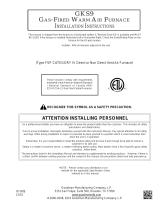
Furnace Suspension
If suspending the furnace from rafters or joist, use 3/8"
threaded rod and 2”x2”x1/8” angle iron as shown in the fol-
lowing figure. If the furnace is installed in a crawl space it
must also be suspended from the floor joist or supported by
a concrete pad. Never install the furnace on the ground or
allow it to be exposed to water. The length of rod will de-
pend on the application and the clearances necessary.
TILT OUTWARD TO ALLOW FOR
DOOR AND CIRCULATOR BLOWER
REMOVAL.
3/8" DIAMETER
THREADED ROD
(6 PLACES)
PROVIDE 8" MINIMUM CLEARANCE BETWEEN
CENTER ROD AND FURNACE CABINET
TO ALLOW FOR CIRCULATOR BLOWER REMOVAL.
ASSURE FURNACE IS LEVEL FROM
END TO END.
ON
90% FURNACES MAKE SURE
THE UNIT HAS A SLIGHT
FORWARD TILT WITH THE FRONT
OF THE FURNACE 0"-3/4"
BELOW THE BACK OF THE FURNACE.
POSITION AS CLOSE AS POSSIBLE
TO BLOWER DECK TO ALLOW FOR
CIRCULATOR BLOWER REMOVAL.
2"X2"X1/8"
ANGLE IRON
(3 PLACES)
HOLD DOWN
NUTS
SUPPORT
NUTS
CONDENSATE
DRAIN
GAS PIPING
ALTERNATE
GAS PIPING
90% Suspended Furnace Shown
EXISTING FURNACE REMOVAL
NOTE: When an existing furnace is removed from a venting
system serving other appliances, the venting system may
be too large to properly vent the remaining attached appli-
ances.
The following vent testing procedure is reproduced from the
American National Standard/National Standard of Canada for
Gas-Fired Central Furnaces ANSI Z21.47, latest edition,
CSA-2.3b, latest edition Section 1.23.1.
The following steps shall be followed with each appliance connected to
the venting system placed in operation, while any other appliances
connected to the venting system are not in operation:
a. Seal any unused openings in the venting system;
b. Inspect the venting system for proper size and horizontal pitch,
as required by the National Fuel Gas Code, ANSI Z223.1 or the
CSA B149 Installation Codes and these instructions. Determine
that there is no blockage or restriction, leakage, corrosion and
other deficiencies which could cause an unsafe condition;
c. In so far as practical, close all building doors and windows and
all doors between the space in which the appliance(s) connected
to the venting system are located and other spaces of the building.
Turn on clothes dryers and any appliance not connected to the
venting system. Turn on any exhaust fans, such as range hoods
and
bathroom exhausts, so they shall operate at maximum speed.
Do not operate a summer exhaust fan. Close fireplace dampers;
d. Follow the lighting instructions. Place the appliance being in-
spected in operation. Adjust thermostat so appliance shall
operate continuously;
e. Test for draft hood equipped spillage at the draft hood relief
opening after 5 minutes of main burner operation. Use the flame
of a match or candle;

INSTALLATION CONSIDERATIONS
13
space with other gas appliances, such as a water heater,
ensure there is an adequate supply of combustion and ven-
tilation air for the other appliances. Refer to the latest edi-
tion of the National Fuel Gas Code NFPA 54/ANSI Z223.1
(Section 9.3), or CAN/CGA B149 Installation Codes (Sec-
tions 7.2, 7.3, or 7.4), or applicable provisions of the local
building codes for determining the combustion air require-
ments for the appliances.
Most homes will require outside air be supplied to the fur-
nace area by means of ventilation grilles or ducts connect-
ing directly to the outdoors or spaces open to the outdoors
such as attics or crawl spaces.
The following information on air for combustion and ventilation
is reproduced from the National Fuel Gas Code NFPA 54/ANSI
Z223.1 Section 9.3.
9.3* Air for Combustion and Ventilation.
9.3.1 General.
9.3.1.1 Air for combustion, ventilation, and dilution of flue gases for
appliances installed in buildings shall be obtained by application of one
of the methods covered in 9.3.2 through 9.3.6. Where the requirements
of 9.3.2 are not met, outdoor air shall be introduced in accordance with
methods covered in 9.3.3 through 9.3.6.
Exception No. 1: This provision shall not apply to direct vent appliances.
9.3.1.2 Appliances of other than natural draft design and other than
Category 1 vented appliances shall be provided with combustion, ven-
tilation, and dilution air in accordance with the appliance manufacturer’s
instructions.
9.3.1.3 Appliances shall be located so as not to interfere with proper
circulation of combustion, ventilation, and dilution air.
9.3.1.4 Where used, a draft hood or a barometric draft regulator shall be
installed in the same room or enclosure as the appliance served so as to
prevent any difference in pressure between the hood or regulator and the
combustion air supply.
9.3.1.5 Makeup air requirements for the operation of exhaust fans, kitchen
ventilation systems, clothes dryers, and fireplaces shall be considered in
determining the adequacy of a space to provide combustion air require-
ments.
9.3.2 Indoor Combustion Air. The required volume of indoor air shall
be determined in accordance with the method in 9.3.2.1 or 9.3.2.2 ex-
cept that where the air infiltration rate is known to be less than 0.40
ACH, the method in 9.3.2.2 shall be used. The total required volume
shall be the sum of the required volume calculated for all appliances
located within the space. Rooms communicating directly with the space
in which the appliances are installed through openings not furnished
with doors, and through combustion air openings sized and located in
accordance with 9.3.2.3, are considered a part of the required volume.
9.3.2.1* Standard Method. The minimum required volume shall be 50
ft
3
per 1,000/Btu/hour (4.8m
3
/kW).
9.3.2.2* Known Air Infiltration Rate Method. Where the air infiltra-
tion rate of a structure is known, the minimum required volume shall be
determined as follows:
(1) For appliances other than fan-assisted, calculate using the following
equation:
21 ft
3
I
other
Required Volume
other
> ________ _________
ACH 1000 Btu/hr
(2) For fan-assisted appliances, calculate using the following equation:
15 ft
3
I
fan
Required Volume
fan
> ________ _________
ACH 1000 Btu/hr
where:
I
other
= all appliances other than fan-assisted input in Btu per
hour
I
fan
= fan-assisted appliances input in Btu per hour
ACH = air change per hour (percent of volume of space exchanged
per hour, expressed as a decimal)
(3) For purposes of this calculation, an infiltration rate greater than
0.60 ACH shall not be used in the equations in 9.3.2.2(1) and
9.3.2.2(2).
9.3.2.3 Indoor Opening Size and Location. Openings used to con-
nect indoor spaces shall be sized and located in accordance with the
following:
(1)*Combining spaces on the same story. Each opening shall have a
minimum free area of 1 in.
2
/1000Btu/hr (2200 mm
2
/kW) of the total
input rating of all appliances in the space but not less than 100 in.
2
(0.60m
2
). One opening shall commence within 12 in. (300 mm) of
the top, and one opening shall commence within 12 in. (300 mm) of
the bottom, of the enclosure [see Figure A.9.3.2.3(1)]. The mini-
mum dimension of air openings shall be not less than 3 in. (80 mm).
Furnace
Water
Heater
Opening
Chimney or Gas Vent
Opening
NOTE: Each opening must have
a free area of not less than one
square inch per 1000 BTU of
the total input rating of all equip-
ment in the enclosure, but not
less than 100 square inches.
Figure A.9.2.3.3.(1) All Combustion Air from Adjacent
Indoor Spaces through Indoor Combustion Air Openings.
(2) Combining spaces in different stories. The volumes of spaces in
different stories shall be considered as communicating spaces where
such spaces are connected by one or more openings in doors or
floors having a total minimum free area of 2 in.
2
/1000 Btu/hr (4400
mm
2
/kW) of total input rating of all appliances.
9.3.3 Outdoor Combustion Air. Outdoor combustion air shall be
provided through opening(s) to the outdoors in accordance with the
methods in 9.3.3.1 or 9.3.3.2. The minimum dimension of air openings
shall not be less than 3 in. (80 mm).
(
)
(
)

INSTALLATION CONSIDERATIONS
14
9.3.3.1 Two Permanent Openings Method. Two permanent open-
ings, one commencing within 12 in. (300 mm) of the top and one com-
mencing within 12 in. (300 mm) of the bottom, of the enclosure shall be
provided. The openings shall communicate directly, or by ducts, with
the outdoors or spaces that freely communicate with the outdoors, as
follows:
(1)*Where directly communicating with the outdoors or where commu-
nicating to the outdoors through vertical ducts, each opening shall
have a minimum free area of 1 in.
2
/4000 Btu/hr (550 min
2
/kW) of
total input rating of all appliances in the enclosure. [See Figure
A.9.3.3.1(1)(a) and Figure A.9.3.3.1(1)(b).]
Furnace
Water
Heater
Outlet Air
Chimney or Gas Vent
NOTE: The inlet and outlet air
openings must each have a free
area of not less than one square
inch per 4000 BTU of the
total input rating of all equipment
in the enclosure.
Inlet Air
Ventilation louvers for
unheated crawl space
A
lternate
air inlet
Ventilation louvers
(each end of attic)
Figure A.9.3.3.1(1)(a) All Combustion Air From Outdoors -
Inlet Air from Ventilated Crawl Space and Outlet Air
to Ventilated Attic.
Furnace
Water
Heater
Outlet Air
Chimney or Gas Vent
NOTE: The inlet and outlet air
openings must each have a free
area of not less than one square
inch per 4000 BTU of the
total input rating of all equipment
in the enclosure.
Inlet air duct
[ends 1 ft (300 mm)
above floor]
Ventilation louvers
(each end of attic)
Figure A.9.3.3.1(1)(b) All Combustion Air
From Outdoors through Ventilated Attic.
(2)*Where communicating with the outdoors through horizontal ducts,
each opening shall have a minimum free area of 1 in.
2
/2000 Btu/hr
(1100 min
2
/kW) of total input rating of all appliances in the enclo-
sure. [See Figure A.9.3.3.1(2).]
Furnace
Water
Heater
Chimney or Gas Vent
NOTE: The air duct openings
must have a free area of not
less than one square inch per
2000 BTU of the total input
rating of all equipment in the
enclosure*.
Outlet air duct
Inlet air duct
Figure A.9.3.3.1(2) All Combustion Air From Outdoors
through Horizontal Ducts.
9.3.3.2* One Permanent Opening Method. One permanent open-
ings, commencing within 12 in. (300 mm) of the top of the enclosure,
shall be provided. The appliance shall have clearances of at least 1 in.
(25 mm) from the sides and back and 6 in. (150 mm) from the front of
the appliance. The opening shall directly communicate with the out-
doors or shall communicate through a vertical or horizontal duct to the
outdoors or spaces that freely communicate with the outdoors (see
Figure A.9.3.3.2) and shall have a minimum free area of the following:
(1) 1 in.
2
/3000 Btu/hr (700 mm
2
per kW) of the total input rating of all
appliances located in the enclosure, and
(2) Not less than the sum of the areas of all vent connectors in the
space.
Furnace
Water
Heater
Opening
Chimney or Gas Vent
NOTE: The single opening must have
a free area of not less than one
square inch per 3000 BTU of
the total input rating of all equip-
ment in the enclosure, but not less than
the sum of the areas of all vent
connectors in the confined space.
Alternate
Opening
Location
Figure A.9.3.3.2 All Combustion Air
From Outdoors through Single Combustion Air Opening.
9.3.4 Combination Indoor and Outdoor Combustion Air. The use
of a combination of indoor and outdoor combustion air shall be in
accordance with (1) through (3) (see example calculation in Annex J]:
(1) Indoor Openings: Where used, openings connecting the interior
spaces shall comply with 9.3.2.3.
(2) Outdoor Opening(s) Location. Outdoor opening(s) shall be lo-
cated in accordance with 9.3.3.
(3) Outdoor Opening(s) Size. The outdoor opening(s) size shall be
calculated in accordance with the following:
(a) The ratio of the interior spaces shall be the available volume
of all communicating spaces divided by the required volume.
(b) The outdoor size reduction factor shall be 1 minus the ratio
of interior spaces.

INSTALLATION CONSIDERATIONS
15
(c) The minimum size of outdoor opening(s) shall be the full size
of outdoor opening(s) calculated in accordance with 9.3.3,
multiplied by the reduction factor. The minimum dimension
of air openings shall not be less than 3 in. (80 mm).
9.3.5 Engineered Installations. Engineered combustion air installa-
tions shall provide an adequate supply of combustion, ventilation, and
dilution air and shall be approved by the authority having jurisdiction.
9.3.6 Mechanical Combustion Air Supply. Where all combustion air
is provided by a mechanical air supply system, the combustion air shall
be supplied form outdoors at the minimum rate of 0.35 ft
3
/min per
1000 Btu/hr (0.034 m
3
/min per kW) for all appliances located within
the space.
9.3.6.1 Where exhaust fans are installed, additional air shall be provided
to replace the exhausted air.
9.3.6.2 Each of the appliances served shall be interlocked to the me-
chanical air supply system to prevent main burner operation where the
mechanical air supply system is not in operation.
9.3.6.3 Where combustion air is provided by the building’s mechanical
ventilation system, the system shall provide the specified combustion
air rate in addition to the required ventilation air.
9.3.7 Louvers, Grilles, and Screens.
9.3.7.1 Louvers and Grilles. The required size of openings for com-
bustion, ventilation, and dilution air shall be based on the net free area
of each opening. Where the free area through a design of louver or grille
or screen is known, it shall be used in calculating the size opening
required to provide the free area specified. Where the louver and grille
design and free area are not known, it shall be assumed that wood
louvers will have 25 percent free area, and metal louvers and grilles will
have 75 percent free area. Nonmotorized louvers and grilles shall be
fixed in the open position.
9.3.7.2 Minimum Scree Mesh Size. Screens shall not be smaller than
1/4 in. mesh.
9.3.7.3 Motorized Louvers. Motorized louvers shall be interlocked
with the appliance so they are proven in the full open position prior to
main burner ignition and during main burner operation. Means shall be
provided to prevent the main burner form igniting should the louver fail
to open during burner startup and to shut down the main burner if the
louvers close during burner operation.
9.3.8 Combustion Air Ducts. Combustion air ducts shall comply with
9.3.8.1 through 9.3.8.8.
9.3.8.1 Ducts shall be constructed of galvanized steel or a material
having equivalent corrosion resistance, strength, and rigidity.
Exception: Within dwellings units, unobstructed stud and joist spaces
shall not be prohibited from conveying combustion air, provided that
not more than one fireblock is removed.
9.3.8.2 Ducts shall terminate in an unobstructed space, allowing free
movement of combustion air to the appliances.
9.3.8.3 Ducts shall serve a single space.
9.3.8.4 Ducts shall not serve both upper and lower combustion air
openings where both such openings are used. The separation between
ducts servicing upper and lower combustion air openings shall be main-
tained to the source of combustion air.
9.3.8.5 Ducts shall not be screened where terminating in an attic space.
9.3.8.6 Horizontal upper combustion air ducts shall not slope down-
ward toward the source of combustion air.
9.3.8.7 The remaining space surrounding a chimney liner, gas vent,
special gas vent, or plastic piping installed within a masonry, metal, or
factory built chimney shall not be used to supply combustion air.
Exception: Direct vent appliances designed for installation in a solid
fuel-burning fireplace where installed in accordance with the
manufacture’s installation instructions.
9.3.8.8 Combustion air intake openings located on the exterior of the
building shall have the lowest side of the combustion air intake open-
ings located at least 12 in. (300 mm) vertically from the adjoining grade
level.
Horizontal Applications and Considerations
Horizontal applications, in particular, may dictate many of
the installation’s specifics such as airflow direction, duct-
work connections, flue and/or combustion air pipe connec-
tions, etc. The basic application of this furnace as a hori-
zontal furnace differs only slightly from an upright installa-
tion.
Horizontal Installations
1. Horizontal installations require 5.5" under the furnace
to accommodate the drain trap.
2. Horizontal furnaces must be installed with ¾” slope from
back to front to permit condensate flow towards the
front of the furnace.
When installing a *MEC96 horizontally with the left side
down, there are two options for connecting the vent pipe to
the furnace.
1. Venting may be connected to the furnace vent pipe fit-
ting on the original top (now the end) of the furnace
2. The internal vent pipe and elbow may be removed from
the furnace to permit the vent to exit the top (original
side) of the furnace. If this option is used, an RF000142
Vent-Drain coupling must be used to keep condensate
from collecting in the inducer assembly
Refer to the following instructions and illustration.

INSTALLATION CONSIDERATIONS
16
Insert flange. Cut 2 ½” long.
R 000142F
C
U
T
H
E
R
E
Vent/Flue Pipe Cuts
1. Remove screws from the vent flange.
2. Remove the internal elbow and vent pipe
3. Cut 2 1/2" from the flange .
4. Remove cabinet plug adjacent to inducer outlet and
install an original cabinet vent hole.
5. Install RF000142 coupling on inducer outlet.
6. Install flanged vent section removed in step 2 and se-
cure with clamps.
7. Secure flange to cabinet using screws removed in step1.
Drain Trap and Lines
In horizontal applications the condensate drain trap is se-
cured to the furnace side panel, suspending it below the
furnace. A minimum clearance of 5.5" below the furnace
must be provided for the drain trap. Additionally, the appro-
priate downward piping slope must be maintained from the
drain trap to the drain location. Refer to Condensate Drain
Trap and Lines section in this manual or the installation
instructions for further details. If the drain trap and drain line
will be exposed to temperatures near or below freezing,
adequate measures must be taken to prevent condensate
from freezing. NOTE: The use of insulation and/or heat tape
is recommended. Failure to provide proper condensate drain-
age can result in property damage.
Leveling
Leveling ensures proper condensate drainage from the heat
exchanger and induced draft blower. For proper flue pipe
drainage, the furnace must be level lengthwise from end to
end. The furnace should also be level from back to front or
have a slight tilt with the access doors downhill (approxi-
mately 3/4") from the back panel. The slight tilt allows the
heat exchanger condensate, generated in the recuperator
coil, to flow forward to the recuperator coil front cover.
A
IR
DISCHARGE
Bottom
Return
Duct
Connection
Side
Return
Duct
Connection
Side
Return
Duct
Connection
UPFLOW
UPRIGH
T
Bottom
Return
Duct
Connection
UPFLOW HORIZONTAL
LEFT AIR DISCHARGE
Bottom
Return
Duct
A
IR
DISCHARGE
UPFLOW HORIZONTAL
RIGHT AIR DISCHARGE
90% Furnace Recommended Installation Positions
Alternate Electrical and Gas Line Connections
The furnaces have provisions allowing for electrical and gas
line connections through either side panel. In horizontal ap-
plications the connections can be made either through the
“top” or “bottom” of the furnace.
Drain Pan
A drain pan must be provided if the furnace is installed above
a conditioned area. The drain pan must cover the entire area
under the furnace (and air conditioning coil if applicable).

INSTALLATION CONSIDERATIONS
17
Freeze Protection
If the drain trap and drain line will be exposed to tempera-
tures near or below freezing, adequate measures must be
taken to prevent condensate from freezing. NOTE: The use
of insulation and/or heat tape is recommended. Failure to
provide proper condensate drainage can result in property
damage.
Propane Gas and/or High Altitude Installations
WARNING
P
OSSIBLE PROPERTY DAMAGE, PERSONAL INJURY OR DEATH MAY OCCUR IF
THE CORRECT CONVERSION KITS ARE NOT INSTALLED.
THE APPROPRIATE KITS
MUST BE APPLIED TO INSURE SAFE AND PROPER FURNACE OPERATION.
ALL
CONVERSIONS MUST BE PERFORMED BY A QUALIFIED INSTALLER OR SERVICE
AGENCY.
This furnace is shipped from the factory configured for natu-
ral gas at standard altitude. Propane gas installations re-
quire an orifice change to compensate for the energy con-
tent difference between natural and propane gas.
High altitude installations may require both a pressure switch
and an orifice change. These changes are necessary to com-
pensate for the natural reduction in the density of both the
gas fuel and the combustion air at higher altitude.
Refer to the Accessories Charts in this manual or product
Specification Sheet for a tabular listing of appropriate
manufacturer’s kits for propane gas and/or high altitude in-
stallations. The indicated kits must be used to insure safe
and proper furnace operation. All conversions must be per-
formed by a qualified installer, or service agency.
VENT/FLUE PIPE AND COMBUSTION AIR PIPE
ONLY)
WARNING
F
AILURE TO FOLLOW THESE INSTRUCTIONS CAN RESULT IN BODILY INJURY OR
DEATH.
CAREFULLY READ AND FOLLOW ALL INSTRUCTIONS GIVEN IN THIS
SECTION.
WARNING
UPON COMPLETION OF THE FURNACE INSTALLATION, CAREFULLY INSPECT THE
ENTIRE FLUE SYSTEM BOTH INSIDE AND OUTSIDE THE FURNACE TO ASSURE IT
IS PROPERLY SEALED.
LEAKS IN THE FLUE SYSTEM CAN RESULT IN SERIOUS
PERSONAL INJURY OR DEATH DUE TO EXPOSURE TO FLUE PRODUCTS,
INCLUDING CARBON MONOXIDE.
A condensing gas furnace achieves its high level of efficiency
by extracting almost all of the heat from the products of
combustion and cooling them to the point where condensa-
tion takes place. Because of the relatively low flue gas tem-
perature and water condensation requirements, PVC pipe is
used as venting material.
This furnace must not be connected to Type B, BW, or L
vent or vent connector, and must not be vented into any
portion of a factory built or masonry chimney except when
used as a pathway for PVC as described later in this sec-
tion. Never common vent this appliance with another ap-
pliance or use a vent which is used by a solid fuel appli-
ance.
It is the responsibility of the installer to follow the manufac-
turers’ recommendations and to verify that all vent/flue pip-
ing and connectors are compatible with furnace flue prod-
ucts. Additionally, it is the responsibility of the installer to
ensure that all piping and connections possess adequate
structural integrity and support to prevent flue pipe separa-
tion, shifting, or sagging during furnace operation.
Materials and Joining Methods
WARNING
T
O AVOID BODILY INJURY, FIRE OR EXPLOSION, SOLVENT CEMENTS MUST BE
KEPT AWAY FROM ALL IGNITION SOURCES (I.E., SPARKS, OPEN FLAMES, AND
EXCESSIVE HEAT) AS THEY ARE COMBUSTIBLE LIQUIDS.
A
VOID BREATHING
CEMENT VAPORS OR CONTACT WITH SKIN AND/OR EYES.
Precautions should be taken to prevent condensate from
freezing inside the vent/flue pipe and/or at the vent/flue
pipe termination. It is our recommendation that all vent/
flue piping exposed to temperatures below 35°F for
extended periods of time should be insulated with 1/2”
thick closed cell foam. Also all vent/flue piping exposed
outdoors in excess of the terminations shown in this manual
(or in unheated areas) should be insulated with 1/2” thick
closed cell foam. Inspect piping for leaks prior to installing
insulation.
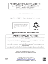
The following bullets and diagram describe the restrictions
concerning the appropriate location of vent/flue pipe and
combustion air intake pipe (when applicable) terminations.
Refer to or the installation instructions for specific details
on termination construction.
• All terminations must be located at least 12 inches
above ground level or the anticipated snow level.
• Vent terminations must terminate at least 3 feet
above any forced air inlet located within 10 feet.
NOTE: This provision does not apply to the combus-
tion air intake termination of a direct vent applica-
tion.
• The vent termination of a non-direct vent application
must terminate at least 4 feet below, 4 feet horizon-
tally from, or 1 foot above any door, window, or grav-
ity air inlet into any building.
• The vent termination of a direct vent application must
terminate at least 12 inches from any opening through
which flue gases may enter a building (door, win-
dow, or gravity air inlet).

INSTALLATION CONSIDERATIONS
18
• The vent termination of vent pipe run vertically through
a roof must terminate at least 12 inches above the
roof line (or the anticipated snow level) and be at least
12 inches from any vertical wall (including any antici-
pated snow build up).
• A vent termination shall not terminate over public walk-
ways or over an area where condensate or vapor could
create a nuisance or hazard or could be detrimental
to the operation of regulators, relief valves, or other
equipment.
• The combustion air intake termination of a direct vent
application should not terminate in an area which is
frequently dusty or dirty.
NOTE: In Canada, the B149 Fuel Gas Code takes prece-
dence over the preceding termination restrictions.
12"
12"
NON-DIRECT VENT
VENT/FLUE TERMINATION
NO TERMINATIONS
ABOVE WALKWAY
12"
4'
4'
NON-DIRECT VENT
VENT/FLUE TERMINATION
DIRECT VENT
VENT/FLUE TERMINATION
12"
10'
3"
FORCED AIR
INLET
OTHER THAN
COMBUSTION AIR
TERMINATION INTAKE
GRADE OR HIGHEST
ANTICIPATED
SNOW LEVEL
90% Furnace Vent Termination Clearances
WARNING
T
HE RUBBER ELBOW IS NOT DESIGNED TO SUPPORAT A LOAD.
W
HEN THE
RUBBER ELBOW IS MOUNTED EXTERNALLY TO THE FURNACE CABINET,
EXTREME CARE MUST BE TAKEN TO ADEQUATELY SUPPORT FIELD-SUPPLIED
VENT/FLUE PIPING, AS DAMAGE CAN RESULT IN LEAKS CAUSING BODILY
INJURY OR DEATH DUE TO EXPOSURE TO FLUE GASES, INCLUDING CARBON
MONOXIDE.
Vent/Flue Pipe Lengths (Non-Direct Vent) and Diam-
eters
Refer to the following tables for applicable length, elbows,
and pipe diameter for construction of the vent/flue pipe sys-
tem of a non-direct vent installation. In addition to the vent/
flue pipe, a single 90° elbow must be secured to the com-
bustion air intake to prevent inadvertent blockage. The tee
or elbows used in the vent/flue termination must be included
when determining the number of elbows in the piping sys-
tem.
12345678
40,000
2
or 2 1/2
120 115 110 105 100 95 90 85
60,000
2
or 2 1/2
95 90 85 80 75 70 65 60
80,000 "B" 2 or 2 1/2 75 70 65 60 55 50 45 40
80,000 "B" 3 200 193 186 179 172 165 158 151
80,000 "C" 2 or 2 1/2 25 20 15 10 5 N/A N/A N/A
80,000 "C" 3 200 193 186 179 172 165 158 151
100,000 2 or 2 1/2 25 20 15 10 5 N/A N/A N/A
100,000 3 200 193 186 179 172 165 158 151
120,000 2 or 2 1/2 45 40 35 30 25 20 15 10
120,000 3 95 90 85 80 75 70 65 60
*MEC96 Direct Vent (2 - Pipe) and Non-Direct Vent (1- Pipe)
(6)
Maximum Allowable Length of Vent/Flue Pipe
& Combustion Air Pipe (ft)
(1) (2)
Unit Input
(Btu)
Pipe Size
(4)
(in.)
Number of Elbows
(3) (5)
1) Maximum allowable limits listed on individual lengths for inlet and flue and NOT a combination.
2) Minimum requirement for each vent pipe is five (5) feet in length and one elbow/tee.
3) Tee used in the vent/flue termination must be included when determining the number of elbows in
the piping system.
4) 2 1/2” or 3” diameter pipe can be used in place of 2” diameter pipe.
5) Increased Clearance Configurations using (2) 45 deg. Long Sweep elbows should be consid-
ered equivalent to one 90 deg. elbow.
6) One 90° elbow should be secured to the combustion air intake connection.
12" MINIMUM
VENT/FLUE TEE
OR
90° ELBOW TURNED
DOWN
12" MINIMUM ABOVE
HIGHEST ANTICIPATED
SNOW LEVEL
90% Furnace Horizontal Termination (Single Pipe)
Above Highest Anticipated Snow Level

INSTALLATION CONSIDERATIONS
19
NOTE: Terminate both pipes in the same pressure zone
(same side of roof, no major obstacles between pipes,
etc.).
COMBUSTION AIR INTAKE
(OPTIONAL)
*Not required for
single pipe installation
TEE (OPTIONAL)
9
6
”
M
A
X
.
-
3
”
M
I
N
.
R
O
O
F
L
I
N
E
INTAKE
SCREEN
OPTIONAL
12” MIN
HEIGHT DIFFERENCE
BETWEEN
INTAKE AND VENT
12” MIN TO ROOF OR HIGHEST
ANTICIPATED SNOW LEVEL
STRAIGHT
ELBOWS
VENT/FLUE TEE (
or
45° ELBOW
TURNED DOWN or
90° ELBOW TURNED
DOWN
OPTIONAL)
12" MIN. ABOVE
HIGHEST ANTICIPATED
SNOW LEVEL
12" MIN.
Horizontal Termination (Single Pipe)
Above Highest Anticipated Snow Level
90º OR 45°
ELBOW
SCREEN
(OPTIONAL)
12" MIN. TO GRADE OR
HIGHEST ANTICIPATED
SNOW LEVEL
6” MAX
10”- 24”
4” MIN
Standard Horizontal Terminations (Dual Pipe)
SCREEN
(OPTIONAL)
AIR
INTAKE
90°
ELBOWS
12" MIN. ABOVE
HIGHEST ANTICIPATED
SNOW LEVEL
3” - 24”
Alternate Horizontal Vent Termination (Dual Pipe)
SCREEN
(OPTIONAL)
AIR
INTAKE
90°
ELBOWS
12" MIN. ABOVE
HIGHEST ANTICIPATED
SNOW LEVEL
3”-24” BETWEEN PIPES
Combustion Air Intake may also be snorkeled to obtain 12” min ground
clearance.
Alternate Vent Termination Above Anticipated Snow Level
(Dual Pipe)

INSTALLATION CONSIDERATIONS
20
VENT/INTAKE T ERMINATIONS F OR INSTALLATION OF M UL-
TIPLE D IRECT V ENT F URNACES
If more than one direct vent furnace is to be installed verti-
cally through a common roof top, maintain the same mini-
mum clearances between the exhaust vent and air intake
terminations of adjacent units as with the exhaust vent and
air intake terminations of a single unit.
If more than one direct vent furnace is to be installed hori-
zontally through a common side wall, maintain the clear-
ances as in the following figure. Always terminate all ex-
haust vent outlets at the same elevation and always termi-
nate all air intakes at the same elevation.
3” MIN
12” MIN TO GRADE OR HIGHEST
ANTICIPATED SNOW LEVEL
12” MIN SEPARATION
3” - 24”
OPTIONAL
INTAKE
SCREENS
Termination of Multiple Direct Vent Furnaces
Direct Vent
Terminal
50,000 Btuh
or less
9"
12"
12"
12"
Direct Vent Term inal
More than 50,000 Btuh
Forced Air Inlet
3'
G
R
A
D
E
FIGURE 1
(DCVK) Vent Termination Clearances
1. The vent termination must be located at least 12” above
ground or normally expected snow accumulation levels.
2. Do NOT terminate over public walkways. Avoid areas
where condensate may cause problems such as above
planters, patios, or adjacent to windows where steam
may cause fogging.
3. The vent termination shall be located at least 4’
horizontally from any electric meter, gas meter,
regulator and any relief equipment. These distances
apply ONLY to U.S. Installations.
4. The vent termination shall be located at least 3’ above
any forced air inlet located within 10’; and at least 10’
from a combustion air intake of another appliance,
except another direct vent furnace intake.
5. In Canada, the Canadian Fuel Gas Code takes
precedence over the preceding termination instructions.
3" or 4" Diameter
SDR-26 Pipe
2 or 2 1/2" Diameter
SDR-26 Pipe
2" or 3" Diameter
Y Concentric Fitting
2" or 3" Diameter
Rain Cap
These kits are for vertical or horizontal termination of the
combustion air inlet and the exhaust vent pipes on Category
IV gas-fired condensing furnaces. The DCVK-30 (CVENT-
3) kit can be used for 3” diameter pipe systems. The DCVK-
20 (CVENT-2) kit can be used for the 2” diameter pipe
system. Both the combustion air inlet and the exhaust vent
pipes must attach to the termination kit. The termination
kit must terminate outside the structure and must be installed
per the instructions outlined below for vertical or horizontal
termination. Vertical termination is preferred. Field supplied
pipe and fittings are required to complete the installation.
1. Determine the best location for the termination kit. Roof
termination is preferred since it is less susceptible to
damage, has reduced intake contaminants and less
visible vent vapors. For side termination, consideration
should be given to:
a. Possible damage from the vapors to plants/shurbs,
other equipment and building materials
b. Possible damage to the terminal from foreign ob-
jects
c. Wind effects that may cause recirculation of flue
products, debris or light snow
d. Visible vent vapors.
/