8
The 80% gas furnaces are design
certified by CSA for use with natural and
propane gases as follows:
As a Category I furnace, it may be
vented vertically with type B-1 vent
pipe and also may be common
vented as described in these
instructions.
This furnace should be installed in
accordance with the American National
Standard Z223.1 - latest edition booklet
entitled “National Fuel Gas Code”
(NFPA 54) (in Canada, CSA B149.1 and
.2 Installation Codes for gas burning
appliances), and the requirements or
codes of the local utility or other
authority having jurisdiction including
local plumbing or waste water codes.
The National Appliance Energy
Conservation Act (NAECA) of 1987
states that any gas furnace
manufactured after January 1, 1992,
must have a minimum Annual Fuel
Utilization Efficiency (AFUE) of 78%.
The higher the AFUE percentage the
more usable heat energy the consumer
gets for every dollar of fuel purchased.
This is similar to the EPA's minimum gas
mileage requirement for automobiles. It
gives the consumer a relatively easy
way to make direct efficiency
comparisons between different furnace
brands and styles.
A high AFUE value, which translates into
a low operating cost, is not the only
concern that consumers have. They also
want a furnace with a reasonable
installed cost. They want a furnace that
provides them with comfort – their main
concern. And they expect a furnace with
exceptional reliability and longevity.
Gas furnace manufacturers are always
striving to provide consumers with the
best furnace value. The Low Profile
Furnace addresses all those consumer
needs. It gives exceptional efficiency
with a low installation cost. It delivers the
comfort the customer wants along with
the reliability they expect.
The key to all these customer benefits is
the furnace's heat exchanger. The
materials used to construct the furnace
in general and the heat exchanger in
particular make it a rugged, long lasting
unit. The unique heat exchanger design
provides the customer with a furnace
only 34 inches high. This gives the
consumer a unit easily installed in
almost every location that accepts all
customary accessories.
With the introduction of higher efficiency
furnaces, special attention must be paid
to the venting system. Only listed
venting systems may be used as stated
in the installation instructions and the
National Fuel Gas Code, ANSI Z223.1
(NFPA 54), or the Canadian CAN/CGA
B149.1 and B149.2 Installation Codes
for Gas Burning Appliances. Since
furnace technology and venting
requirements are changing, awareness
of local, state, and federal codes and
industry changes is imperative.
GENERAL INFORMATION
IMPORTANT INFORMATION
ABOUT EFFICIENCY AND
INDOOR AIR QUALITY
Central cooling and heating equipment
is only as efficient as the duct system
that carries the cooled or heated air. To
maintain efficiency, comfort and good
indoor air quality, it is important to have
the proper balance between the air
being supplied to each room and the air
returning to the cooling and heating
equipment.
Proper balance and sealing of the duct
system improves the efficiency of the
heating and air conditioning system
and improves the indoor air quality of
the home by reducing the amount of
airborne pollutants that enter homes
from spaces where the ductwork and /
or equipment is located. The
manufacturer and the U.S.
Environmental Protection Agency’s
Energy Star Program recommend that
central duct systems be checked by a
qualified contractor for proper balance
and sealing.
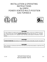
DUCT LEAKS CAN CREATE AN
UNBALANCED SYSTEM AND DRAW
POLLUTANTS SUCH AS DIRT, DUST,
FUMES AND ODORS INTO THE
HOME CAUSING PROPERTY
DAMAGE. FUMES AND ODORS
FROM TOXIC, VOLATILE OR
FLAMMABLE CHEMICALS, AS WELL
AS AUTOMOBILE EXHAUST AND
CARBON MONOXIDE (CO), CAN BE
DRAWN INTO THE LIVING SPACE
THROUGH LEAKING DUCTS AND
UNBALANCED DUCT SYSTEMS
CAUSING PERSONAL INJURY OR
DEATH (SEE FIGURE 1).
• IF AIR-MOVING EQUIPMENT OR
DUCTWORK IS LOCATED IN
GARAGES OR OFF-GARAGE
STORAGE AREAS - ALL JOINTS,
SEAMS, AND OPENINGS IN THE
EQUIPMENT AND DUCT MUST BE
SEALED TO LIMIT THE MIGRATION
OF TOXIC FUMES AND ODORS
INCLUDING CARBON MONOXIDE
FROM MIGRATING INTO THE
LIVING SPACE.
FIGURE 1
MIGRATION OF DANGEROUS SUBSTANCES, FUMES, AND ODORS INTO LIVING SPACES
NOTE: Always perform a proper heat
loss calculation before specifying the
furnace size. This ensures that the
furnace is sized to adequately,
economically, heat the building and
provide the correct airflow for your
application.
IMPORTANT: PROPER APPLICATION,
INSTALLATION AND MAINTENANCE
OF THIS FURNACE IS A MUST IF
CONSUMERS ARE TO RECEIVE THE
FULL BENEFITS FOR WHICH THEY
HAVE PAID.
Additional helpful publications available
from the “National Fire Protection
Association” are: NFPA-90A –
Installation of Air Conditioning and
Ventilating Systems 1985 or latest
edition. NFPA-90B – Warm Air Heating
and Air Conditioning Systems 1984.
These publications are available from:
National Fire Protection Association,
Inc.
Batterymarch Park
Quincy, MA 02269
CSA-INTERNATIONAL
178 Rexdale Blvd.
Etobicoke (Toronto), Ontario
Canada M9W, 1R3
WARNING
!