Page is loading ...

2017-01-09
EN
0000000310
V.002
X.38.0
3204
93218-001
PE-K Pellet Boiler
105-140 kW
Service manual

ETA Heiztechnik
Gewerbepark 1
A-4716 Hofkirchen an der Trattnach
Tel: +43 (0) 7734 / 22 88 -0
Fax: +43 (0) 7734 / 22 88 -22
www.eta.co.at

General information
3
1 General information
Support for cleaning and maintenance
This document helps support you with the cleaning
and maintenance of the boiler. The required steps are
listed in detail here.
Take note of the date of the cleaning or maintenance
and any faults that may have occurred. This facilitates
troubleshooting for the expert (system operator,
heating technician...).
For services (such as commissioning, mainte-
nance, fault fixing provided by ETA customer
service), the service reports are provided in digital
form. For clarity, you should staple these reports to this
document or enclose them.
Commissioning data
Enter the boiler number (printed on the type plate), the
date of commissioning as well as the heating
technician who commissioned the system.
Copyright
All contents of this document are property of ETA
Heiztechnik GmbH and are protected by copyright.
Any reproduction, transfer to third parties or use for
other purposes is prohibited without written permission
from the owner.
Subject to technical changes
We reserve the right to make technical modifications
without notice. Printing and typesetting errors or
changes of any kind made in the interim are not cause
for claims. Individual configurations depicted or
described here are only available optionally. In the
event of contradictions between individual documents
regarding delivery scope, the information in our current
price list applies.
Explanation of symbols
Instructions and information
Layout of safety instructions
SIGNAL WORD!
Type and source of danger
Possible effects
• Measures for avoiding the danger
Types of safety instruction
CAUTION!
On non-compliance with this safety instruction, there is
a risk of material damage.
WARNING!
On non-compliance with this safety instruction, there is
a risk of physical injury.
DANGER!
On non-compliance with this safety instruction, there is
a risk of major physical injury.
Commissioning data
Boiler number:
________________________________________
Commissioned on:
_________________________________________
Commissioned by (company):
_________________________________________
_________________________________________
_________________________________________

4 www.eta.co.at
Maintenance notes Cleaning and maintenance
2 Cleaning and maintenance
2.1 Maintenance notes
Performing regular cleaning and maintenance
To ensure satisfactory functioning, cleaning and
maintenance must be performed at regular intervals.
Carry out this work within the intervals stated here.
All tasks where the maintenance table reads
"Customer" or "Customer or expert" in the column
"To be carried out by" can be carried out by any trained
adult. Instructions can be provided by the heating
technician or our customer service.
Steps that are marked with "Expert" only can only be
carried out by the heating technician or our customer
service.
Operation only by trained personnel
The product may be operated by trained adults only.
Training may be provided by the heating technician or
our customer service. Please read the associated doc-
umentation carefully in order to avoid errors during
operation and maintenance.
Persons who lack experience and knowledge as well
as children may not operate, clean, or maintain the
product.
Explanation of pictograms
Switch the boiler on/off with the mains switch.
Perform a visual check of the components.
Clean the components, for example, with a
soft cloth.
Remove deposits with a vacuum or an ash
vacuum.
Remove deposits with the poker.
Remove deposits with the cleaning brush.
Replace the wear parts (e.g. seals) on the
components.
Lubricate the components. The lubricant to
use is listed in the respective step.
Install the components with some force (for
example the retaining tube or the Lambda
probe).
Handle the components carefully, since they
break very easily.
Clean panels
If necessary, clean the panels of the boiler and the
ETAtouch screen with a moist cloth.
Under no circumstances use aggressive
solvents, chemicals or scouring agents. They can
lead to stress cracks and damage.
Checking the boiler counters
The counters can be seen in the boiler's text menu.
Counter [Full load hours since maint.] is used for the
service intervals. If it has reached one of the listed
intervals, maintenance is required. This counter is in:
Counters
Full load hours since maint.

Cleaning and maintenance Maintenance notes
5

6 www.eta.co.at
Maintenance openings in the boiler Cleaning and maintenance
2.2 Maintenance openings in the
boiler
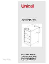
Maintenance openings and components
The illustration depicts a boiler with the pellet
hopper on the left side.
1 Combustion chamber door
2 Secondary air actuator (mirrored for pellet hopper
on the right side)
3 Drive for tilting grate (mirrored for pellet hopper on
the right side)
4 Maintenance cover for flue gas recirculation
5 Primary air actuator (mirrored for pellet hopper on
the right side)
6 Firebed switch (mirrored for pellet hopper on the
right side)
7 Stoker drive chains

Cleaning and maintenance Maintenance openings in the boiler
7
1 Maintenance cover for flue gas recirculation
2 Flue gas temperature sensor
3 Heat exchanger cleaner
4 Frequency converter
5 Fill level sensor in pellet hopper
6 Ignition
7 Stoker drive chains
8 Maintenance cover for flue gas recirculation
9 Plug screw for lubricating the de-ashing system's
drive chain
10 Draught fan

8 www.eta.co.at
Maintenance table Cleaning and maintenance
2.3 Maintenance table
Tasks
Regular
ly
Every
2500 h
or
1 year
Every
5000 h
or
3years
to be
performed by
Empty the ash box
• Remove excess ash from secondary combustion chamber
• Empty the ash box
• Check the seals
X X X Customer
Check the pressure of the heating system X X X Customer
Check safety devices
• Visual check of the safety valves
• Visual check of the thermal relief valve
X X
Customer or
specialist
Chimney
• Clean the flue tube
• Flush the chimney's condensate drain
X X
Customer or
specialist
Clean combustion chamber
• Clean inside of the secondary combustion chamber
• Clean tilting grate
• Clean secondary air openings
• Clean ignition tubes
• Check firebed button and firebed switch
• Check refractory lining
X X
Customer or
specialist
Clean heat exchanger
• Clean heat exchanger and downdraft channel
• Clean lambda probe
• Check heat exchanger tubes
• Check heat exchanger cleaner
• Clean the housing of the frequency converter
• Inspect seals on heat exchanger covers
X X
Customer or
specialist
Clean flue gas recirculator
• Clean flue gas recirculation piping
• Inspecting seals on maintenance covers
X X
Customer or
specialist
Clean the draught fan X Specialist
Clean the temperature sensor X Specialist
Check air valve for primary and secondary air X Specialist
Lubricate the grate drive X Specialist
Check the ash box position switch X Specialist
Check de-ashing system X Specialist
Check boiler doors X Specialist
Check the stoker unit
• Check the stoker drive chains
X Specialist
Clean ignition X Specialist
Check the pellet hopper
• Clean the fill level sensor
• Clean the strainer
X Specialist
Calibrate the lambda probe X Specialist

Cleaning and maintenance Maintenance table
9
Reset the maintenance counter X Specialist
Perform heating test X Specialist
Tasks
Regular
ly
Every
2500 h
or
1 year
Every
5000 h
or
3years
to be
performed by

10 www.eta.co.at
Regularly Cleaning and maintenance
2.4 Regularly
2.4.1 Preparation
Stop heating
End the boiler's heating mode with the On/Off switch
in the boiler overview window. The boiler
performs an ember burnout and then changes to
[Switched off] mode. Press the [De-ash] button to
make the boiler perform a final de-ashing.
2.4.2 Empty the ash box
Remove excess ash from secondary combustion
chamber
Open the combustion chamber door and use the poker
to scrape the excess ash into the combustion
chamber.
The ash in the secondary combustion chamber
may not be steeper than 45°.
To remove this ash, initiate boiler de-ashing by
pressing the [De-ash] button.
Empty the ash box, inspect the seals
Use the two sight glasses to check the fill level of
the ash box without opening it.
Fig. 2-1: Sight glasses
Open both lateral fasteners by pressing their safety
catches in the direction of the arrow. Remove the ash
box from the boiler.
Close the covers on the ash box and fasten them with
the wing nuts.
Fig. 2-2: Covers

Cleaning and maintenance Regularly
11
Open the fasteners on the lid and empty the ash box.
Fig. 2-3: Check ash
If there are large pieces of slag in the ash, the
combustion chamber and the tilting grate must be
checked and the de-ashing interval reduced, if
necessary.
Inspect the integrity of the seal on the ash box lid, and
replace it if necessary.
Fig. 2-4: Seal
Inspect the integrity of the ash box seals on the boiler,
replace them if necessary.
Fig. 2-5: Seal
Attaching the ash box to the boiler
Reattach the cover of the ash box and secure with the
fasteners. Then re-open the covers.
Fig. 2-6: Covers
Push the ash box over the connection on the boiler and
attach it to the boiler with the fasteners.

12 www.eta.co.at
Regularly Cleaning and maintenance
2.4.3 Check pressure of the heating
system
Check heating system water pressure
In buildings with up to three storeys, the optimum
water pressure in a cold heating system is between 1
and 2 bar. For a warm heating system, the optimum
water pressure is between 1.5 and 2.5 bar.
Fig. 2-7: Pressure gauge
If the water pressure is too low, fill the cold
heating system to approx. 2 bar. Do not fill to a
higher pressure, as water expands with increasing
temperature and the water pressure also rises when
the boiler is in heating mode. The safety valve triggers
at approx. 2.8 bar.
If the water pressure drops several times a year,
contact a heating professional. When refilling
water in the heating system, the same water as used
during initial filling should be used whenever possible
(e.g. prepared water).
2.4.4 Establish operational readiness
Switching on the boiler
Switch the boiler back on with the On/Off
switch.

Cleaning and maintenance 2500 h / annually
13
2.5 2500 h / annually
2.5.1 Preparation
Stop heating
End the boiler's heating mode with the On/Off switch
in the boiler overview window. The boiler
performs an ember burnout and then changes to
[Switched off] mode. Press the [De-ash] button to
make the boiler perform a final de-ashing.
Switch off boiler via mains switch
WARNING!
Switch off the electricity to the boiler via the mains
switch. This prevents injuries caused by switching
the boiler on inadvertently.
WARNING!
Burns caused by hot parts
Risk of burning on parts located behind the
boiler housing, even after shutting the
boiler down.
Allow the boiler to cool down sufficiently
before starting any activities.
2.5.2 Check safety devices
Checking the safety valves
Perform a visual check of all safety valves of the
heating system. The outlets of the safety valves may
not drip.
Fig. 2-8: Safety valve
If the safety valve drips, open it with a quarter turn of
the red cap and rinse it out (danger of scalding). If the
safety valve still cannot be sealed effectively after
being rinsed several times, it must be cleaned or
replaced by an installer (heating technician).
A manual check of the safety valve is carried out
with a 1/4 turn of the red cap. This rinses the
safety valve. However it is very likely that the seal will
be damaged in the process and thus the outlet will drip.
That is why you should only perform this check on
weekdays and never on weekends in cold winter, as no
heating technician may be available if the seal is
defective.

14 www.eta.co.at
2500 h / annually Cleaning and maintenance
Checking the thermal relief valve
Visually examine the thermal relief valve. The outlet
should not drip.
Fig. 2-9: Thermally actuated drain valve
If the relief valve is dripping, rinse it by pressing the red
button (risk of scalding). If the relief valve still cannot
be closed tightly after being rinsed several times, it
must be cleaned by an installer (heating technician) or
replaced.
A manual check of the relief valve is carried out
by pressing the red button. This rinses the relief
valve. However it is very likely that the seal will be
damaged in the process and thus the outlet will drip.
That is why you should only perform this check on
weekdays and never on weekends in cold winter, as no
heating technician may be available if the seal is
defective.
2.5.3 Chimney
Clean the flue tube
Sweep the flue tube from the flue outlet to the chimney
and remove flue ash from the chimney using a vacuum
cleaner.
Fig. 2-10: Flue tube
Sweep the ash into the chimney, not into the
boiler. Otherwise, ash will collect in the
fan housing and can block the draught fan.
Rinse the chimney's condensate drain
Check the chimney's condensate drain to make sure it
is free, as ash can block the outlet. To check, rinse the
outlet with some water.
Fig. 2-11: Condensate drain

Cleaning and maintenance 2500 h / annually
15
2.5.4 Cleaning the combustion chamber
Clean inside of the secondary combustion
chamber
Open the combustion chamber door and scrape all of
the ash from the secondary combustion chamber into
the primary combustion chamber with the poker.
Fig. 2-12: Secondary combustion chamber
Remove the combustion chamber cover in the
secondary combustion chamber.
Fig. 2-13: Combustion chamber cover
Clean tilting grate
The tilting grate cannot be rotated by hand. Therefore,
press the [De-ash] button to de-ash the boiler. The
grate is tilted and remains in this position for approxi-
mately 15 seconds.
WARNING!
Danger of crushing due to tilting grate
When the grate is tilted, switch off the boiler with
the mains switch. This causes the grate to remain
in this position so injuries while cleaning the grate
are prevented.
Use the poker to clean the tilting grate and the
openings in it; let the ash fall down.
Fig. 2-14: Tilting grate
Do not hit the tilting grate with the poker.
Clean secondary air openings
Clean secondary air openings (above the tilting grate).
Fig. 2-15: Secondary air openings

16 www.eta.co.at
2500 h / annually Cleaning and maintenance
Clean ignition tubes
Check the ignition tube for combustion residues and
clean it by vacuuming.
Fig. 2-16: Ignition tubes
Remove the cover on the front
Remove the screws for securing the cover. Push the
cover on the front up slightly, detach and remove it.
Fig. 2-17: Cover
Check firebed button and firebed switch
Check the mobility of the firebed button in the
combustion chamber by repeated lifting.
Fig. 2-18: Firebed button
The firebed switch on the front of the boiler must be
actuated when lifting.
Fig. 2-19: Firebed switch
Mount cover on the front
Mount the cover on the front of the boiler. Also re-install
the screws for securing the cover.
Fig. 2-20: Cover

Cleaning and maintenance 2500 h / annually
17
Check refractory lining
Check the refractory lining of the primary and
secondary combustion chambers for damage and
cracks.
Replace the combustion chamber cover
Reinsert the combustion chamber cover, ensuring that
it is properly centred.
Fig. 2-21: Combustion chamber cover
The convex surface of the combustion chamber
cover must point to the top of the boiler.
2.5.5 Cleaning the heat exchanger
Remove heat exchanger cover
Open the maintenance cover in the top of the boiler
casing and remove the insulating cover.
Fig. 2-22: Insulating cover
Loosen the knurled nuts on the heat exchanger cover
by turning them anti-clockwise and rotate the
ball knobs by 180°.
Fig. 2-23: Knurled nuts and ball knobs
Remove the heat exchanger cover.
Fig. 2-24: Heat exchanger cover

18 www.eta.co.at
2500 h / annually Cleaning and maintenance
Clean heat exchanger and downdraft channel
Remove the internal cover between the secondary
combustion chamber and the heat exchanger.
Fig. 2-25: Internal cover
Brush out the downdraft channel and remove the flue
ash from the heat exchanger, for example with an
ash vacuum.
Fig. 2-26: Heat exchanger and downdraft channel
After cleaning, replace the internal cover. Ensure that
it is firmly seated.
Clean lambda probe
Vacuum out the head of the lambda probe using a
vacuum cleaner. Do not dismantle the lambda probe.
Fig. 2-27: Head of the lambda probe
Check heat exchanger tubes
Check the heat exchanger tubes and the turbulators
for tar deposits.
Fig. 2-28: Heat exchanger tubes

Cleaning and maintenance 2500 h / annually
19
Tar deposits can have several causes, for
example:
• leak air through the heat exchanger cover, the
combustion chamber door or the lambda probe.
• an incorrectly calibrated lambda probe
• insufficient boiler runtime (start-stop operation)
Check heat exchanger cleaner
Remove the cover for the heat exchanger cleaner
drive.
Fig. 2-29: Cover
Lubricate the spring, guide and bearing with a heat-
resistant lubricant.
Fig. 2-30: Lever
Clean the housing of the frequency converter
Clean dust and dirt from the frequency converter
housing.
Fig. 2-31: Frequency converter
Install the cover
Re-attach the cover to the boiler.
Inspect seals on heat exchanger covers
Inspect the integrity of the seals on the heat exchanger
covers and replace if necessary.
Fig. 2-32: Heat exchanger cover

20 www.eta.co.at
2500 h / annually Cleaning and maintenance
CAUTION!
Avoid operation with damaged seals
Never operate the boiler with damaged seals.
Otherwise, leak air is sucked in, disturbing the
combustion process and causing increased wear.
Always replace seals as soon as they are
damaged.
Close heat exchanger cover
Position the heat exchanger cover carefully.
Fig. 2-33: Heat exchanger cover
Turn the ball knobs by 180° to secure the heat
exchanger covers. Then tighten the knurled nuts
evenly and alternately by turning them clockwise.
Fig. 2-34: Knurled nuts and ball knobs
Put the insulating cover back on.
Fig. 2-35: Insulating cover
/