Page is loading ...

2016-04-05
EN
0000000305
V.001
X.36.0
3503
93824-001
Moving-grate boiler
Size 2
Service guide

ETA Heiztechnik
Gewerbepark 1
A-4716 Hofkirchen an der Trattnach
Tel: +43 (0) 7734 / 22 88 -0
Fax: +43 (0) 7734 / 22 88 -22
www.eta.co.at

General information
3
1 General information
Support for cleaning and maintenance
This document helps support you with the cleaning
and maintenance of the boiler. The required steps are
listed in detail here.
Take note of the date of the cleaning or maintenance
and any faults that may have occurred. This facilitates
troubleshooting for the expert (system operator,
heating technician...).
For services (such as commissioning, mainte-
nance, fault fixing provided by ETA customer
service), the service reports are provided in digital
form. For clarity, you should staple these reports to this
document or enclose them.
Commissioning data
Enter the boiler number (printed on the type plate), the
date of commissioning as well as the heating
technician who commissioned the system.
Copyright
All contents of this document are property of ETA
Heiztechnik GmbH and are protected by copyright.
Any reproduction, transfer to third parties or use for
other purposes is prohibited without written permission
from the owner.
Subject to technical alterations
We reserve the right to make technical modifications
without notice. Printing and typesetting errors or
changes of any kind made in the interim are not cause
for claims. Individual configurations depicted or
described here are only optionally available. In the
event of contradictions between individual documents
regarding delivery scope, the information in our current
price list applies.
Explanation of symbols
Instructions and information
Layout of safety instructions
SIGNAL WORD!
Type and source of danger
Possible effects
• Measures for avoiding the danger
Types of safety instruction
CAUTION!
On non-compliance with this safety instruction, there is
a risk of material damage.
WARNING!
On non-compliance with this safety instruction, there is
a risk of physical injury.
DANGER!
On non-compliance with this safety instruction, there is
a risk of major physical injury.
Commissioning data
Boiler number:
________________________________________
Commissioned on:
_________________________________________
Commissioned by (company):
_________________________________________
_________________________________________
_________________________________________

4 www.eta.co.at
Cleaning and maintenance
2 Cleaning and maintenance
Maintenance openings and components
1 Draught fan of flue gas recirculation
2 Maintenance cover for flue gas recirculation piping
3 Draught fan
4 Heat exchanger cover
5 Maintenance cover for reversing chamber on heat
exchanger
6 Combustion chamber door
7 Maintenance cover for flue gas recirculation
(behind panel)
8 Ignition fan
9 Actuator for primary air
10 Maintenance cover for secondary combustion
zone

Cleaning and maintenance
5
1 Drive of heat exchanger cleaner
2 Temperature sensor of combustion chamber
3 Actuator for flue gas recirculation flap
4 Maintenance cover for flue gas recirculation
(behind panel)
5 Boiler mains switch
6 Maintenance cover for reversing chamber on heat
exchanger

6 www.eta.co.at
Cleaning and maintenance
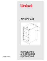
The conveyor depicted here is the standard con-
figuration.
1 Drop chute maintenance cover
2 Rotary valve maintenance cover
3 Safety switch for rotary valve maintenance cover
4 Drop chute safety switch
Fig. 2-1: Rotary valve position sensor

Cleaning and maintenance General information
7
2.1 General information
Operation only by trained personnel
The product may be operated by trained adults only.
Training may be provided by the heating technician or
our customer service. Please read the associated doc-
umentation carefully in order to avoid errors during
operation and maintenance.
Persons who lack experience and knowledge as well
as children may not operate, clean, or maintain the
product.
Performing regular cleaning and maintenance
To ensure satisfactory functioning, cleaning and
maintenance must be performed at regular intervals.
Carry out this work within the intervals stated here.
All tasks where the maintenance table reads
"Customer" or "Customer or expert" in the column
"To be carried out by" can be carried out by any trained
adult. Instructions can be provided by the heating
technician or our customer service.
Steps that are marked with "Expert" only can only be
carried out by the heating technician or our customer
service.
Checking the boiler counters
The counters can be seen in the boiler's text menu.
Counter [Full load hours since maint.] is used for the
service intervals. If it has reached one of the listed
intervals, maintenance is required. This counter is in:
Counters
Full load hours since maint.

8 www.eta.co.at
Maintenance table Cleaning and maintenance
2.2 Maintenance table
Tasks
Regular
ly
Every
3,000 h
or once
a year
Every
6,000 h
or
every
2years
to be done by
Check fill level of ash bins X X X Customer
Check heating system's water pressure X X X Customer
Check air intake in installation room X X Customer
Clean flue tube X X Customer
Clean combustion chamber X X Customer
Check lining of the combustion chamber X X Customer
Check the firebed switch X X Customer
Visual check of the stoker screw X X Customer
Clean ignition fan and openings X X Customer
Check protective elements and grate elements X X Customer
Visual check of the ash cross screw X X Customer
Check grate ash screw X X Customer
Clean roller guide of the moving grate X X Customer
Remove ash from the reversing chamber X X Customer
Check turbulators X X Customer
Clean flue gas recirculation ducts X X Customer/expert
Clean the heat exchanger X X Customer/expert
Clean connection pipe to draught fan X X Customer/expert
Visual check of the heat exchanger screw X X Customer/expert
Clean flue gas temperature sensor X X Customer/expert
Clean flue gas recirculation piping, check flue gas recirculation
flap
X X Customer/expert
Clean draught fan of the flue gas recirculation X X Customer/expert
Lubricate heat exchanger cleaner drive X X Customer/expert
Check stoker drive chain X X Customer/expert
Check the seal of the ash bin or the transfer coupling X X Customer/expert
Check heat exchanger ash screw X X Customer/expert
Clean the lambda probe X X Customer/expert
Visually check safety valves X X Customer/expert
Visually check thermal relief valves X X Customer/expert
Check operational readiness of safety devices in fuel path X X Customer/expert
Clean the upper area of the heat exchanger X Expert
Clean draught fan X Expert
Check seal on heat exchanger cover X Expert
Check safety switch of the discharge X Expert
Check rotary valve stop X Expert
Check silicon hoses for differential pressure switch and
transmitter
X Expert
Check air valve X Expert
Check automatic closing of the actuators X Expert

Cleaning and maintenance Maintenance table
9
Check seal on combustion chamber door X Expert
Calibrate lambda probe X Expert
Perform heating test X Expert
Reset maintenance counter X Expert
Tasks
Regular
ly
Every
3,000 h
or once
a year
Every
6,000 h
or
every
2years
to be done by

10 www.eta.co.at
Regular maintenance Cleaning and maintenance
2.3 Regular maintenance
Check fill level of ash bins
The boiler does not have to be switched off to
empty the ash bins or container.
Before starting the de-ashing emptying, press the
[De-ash] button. This prevents the ash screw
from switching on during the emptying process. If the
ash screw already has a malfunction, first empty the
ash bins or the container and then acknowledge the
fault.
De-ashing with transfer flap
1. Lift the protective mat from the underside. Move
the container to the side and empty.
Fig. 2-2: Protective mat
2. Before placing the protective mat, make sure the
adhesive seal is in a good condition to prevent ash
from escaping.
Fig. 2-3: Seal on the sealing plate
De-ashing with ash bins
1. Turn the locks on the ash bin lid upwards by 90°.
Fig. 2-4: Open the locks
2. Push the lid up and fix in "Park position".
Fig. 2-5: Park position
3. Empty the ash bins. Unhook the lid from "Park
position" and fix to the ash bin with the locks.
DANGER!
Risk of injury from the ash screw
If only one ash bin or none at all is
connected, the ash screw is accessible
from below.
For this reason, operation with only one ash
bin or none at all is prohibited. In addition,
the boiler would take in leak air and hot ash
would fall to the ground, increasing the fire
risk.
The boiler may not be operated for more than
2 minutes without ash bins or an ash container.

Cleaning and maintenance Regular maintenance
11
Check heating system's water pressure
The heating system's water pressure is
measured by the control system and displayed
on the screen. A visual check is still necessary though.
In buildings with up to three storeys, the optimum
water pressure in a cold heating system is between 1
and 2 bar. For a warm heating system, the optimum
water pressure is between 1.5 and 2.5 bar.
If the water pressure is too low, fill the cold heating
system to approx. 2 bar. Do not fill to a higher
pressure, as water expands with increasing
temperature and the water pressure also rises when
the boiler is heating. The safety valve triggers at
approx. 2.8 bar.
If the boiler is operated at maximum 6 bar water
pressure, the values listed above must be
increased accordingly.

12 www.eta.co.at
Every 3000 hours / annually Cleaning and maintenance
2.4 Every 3000 hours / annually
Before this maintenance, perform all steps for the
preceding maintenance intervals
Before this maintenance, all steps for the
preceding maintenance intervals must be
performed.
Stop heating
End the boiler's heating mode with the On/Off switch
in the boiler overview window. The boiler
performs an ember burnout and then changes to
[Switched off] mode. Press the [De-ash] button to
make the boiler perform a final de-ashing.
Switch off boiler via mains switch
WARNING!
Switch off the electricity to the boiler via the mains
switch. This prevents injuries caused by switching
the boiler on inadvertently.
WARNING!
Burns caused by hot parts
Even after the boiler has been switched off,
there will still be a danger of burns caused
by the cleaning and maintenance covers of
the combustion chamber and the heat
exchanger, and by the combustion chamber door.
These parts cool off more slowly, so they may still be
hot.
Allow the boiler cool off long enough, or wear
appropriate protective clothing.
Air intake in installation room must be clear
Air intake for the boiler in installation room must be
clear. It may not be shut or closed.
Cleaning the flue pipe
Sweep the flue pipe from the flue outlet to the chimney,
and remove flue ash from the chimney using a vacuum
cleaner.
Sweep the ash into the chimney, not into the
boiler.
Clean combustion chamber
Carefully pull the temperature sensor of the
combustion chamber out by loosening the screw on
the boiler.
Fig. 2-6: Temperature sensor of combustion chamber
Take off the maintenance cover of the secondary
combustion zone by loosening the 4 screws.
Fig. 2-7: Maintenance cover

Cleaning and maintenance Every 3000 hours / annually
13
Using the poker, remove loose and baked on ash from
the upper part of the combustion chamber. Sweep the
ash backwards into the heat exchanger or forwards
onto the moving grate.
Fig. 2-8: Upper part of the combustion chamber
A thin coating of ash (~ 5 mm) may remain on the
lining. This does not adversely affect operation
and acts as an additional protective layer. Significant
discolouration of the lining is normal.
CAUTION!
Never treat the lining with force, as this may cause
parts of it to be knocked off.
Open the combustion chamber door and remove
baked on ash deposits from around the opening and
from the combustion chamber door
Fig. 2-9: Combustion chamber door
Next, using the poker, remove baked on ash deposits
from inside the combustion chamber and sweep onto
the moving grate.
Fig. 2-10: Lower part of the combustion chamber
A thin coating of ash (~ 5 mm) may remain on the
lining. This does not adversely affect operation
and acts as an additional protective layer. Significant
discolouration of the lining is normal.
Then re-insert the combustion chamber temperature
sensor in the opening and secure with the screw.
Removing ash deposits near the opening of the
secondary combustion zone
Remove ash deposits around the opening of the
secondary combustion zone and also from the
maintenance cover.
Fig. 2-11: Opening of secondary combustion zone
Otherwise, the maintenance cover will not seal
tightly when it is subsequently closed.

14 www.eta.co.at
Every 3000 hours / annually Cleaning and maintenance
Fit maintenance cover for secondary combustion
zone
Remove the ash from the opening for the
maintenance cover with a vacuum cleaner so the
maintenance cover can form a proper seal.
Attach the maintenance cover for the secondary
combustion zone to the boiler using the 4 screws.
Tighten the screws evenly and cross-wise.
Fig. 2-12: Maintenance cover
Cleaning openings in the lining
Clean the openings on both sides of the lining and
remove any baked on ash deposits. Then vacuum the
openings with an ash or vacuum cleaner
Fig. 2-13: Openings in the lining
Check lining of the combustion chamber
After cleaning, check the combustion chamber lining
for cracks or damage.
Significant discolouration of the lining is normal.
Fig. 2-14: Discolourations
Check the firebed switch
Manually actuate the firebed switch and check that it
moves easily.
Fig. 2-15: Firebed switch
In the combustion chamber, check the position of the
firebed switch actuating lever.
Fig. 2-16: Firebed switch actuating lever

Cleaning and maintenance Every 3000 hours / annually
15
Visual check of the stoker screw
Visually check the stoker screw for damage from the
combustion chamber. It can be a bit burnt on the ends
due to the high levels of heat.
It must be replaced if the stoker screw is partially
burnt on the ends.
Fig. 2-17: Stoker screw
Clean ignition fan and photocell
Remove both ignition fans from the boiler.
Fig. 2-18: Removing the ignition fan
Detach the ignition tube by loosening the 4 screws and
remove the ignition rod.
Clean the visible photocell with a soft cloth. Then
reattach the ignition tube.
Also clean the openings in the boiler for the ignition
tube.
Fig. 2-19: Ignition openings
Re-install both ignition fans and attach them to the
boiler with the chain.

16 www.eta.co.at
Every 3000 hours / annually Cleaning and maintenance
Check protective elements and grate elements
Check the protective elements for damage or warping
on both sides of the moving grate.
Fig. 2-20: Protective elements
Also check the individual grate elements for damage.
Fig. 2-21: Grate elements
Visual check of the ash cross screw
From the combustion chamber, visually check the ash
cross screw for damage.
Fig. 2-22: Ash cross screw
Checking the grate ash screw
Lift up the panel slightly and remove from the boiler.
Fig. 2-23: Cover panel
Take off the maintenance cover by loosening the
screws and nuts.
Fig. 2-24: Maintenance cover
Carry out a visual check and remove any possible
foreign bodies (nails, stones...).
Fig. 2-25: Grate ash screw
Inspect the seal of the maintenance cover to ensure it
is in good order, and replace if necessary.
WARNING!
Never operate the boiler with defective seals.
Clean roller guide of the moving grate
Clean the 4 rollers as well as the guides of the moving
grate and check for any possible foreign bodies.

Cleaning and maintenance Every 3000 hours / annually
17
For better checking and cleaning, remove the
panel as well as the maintenance cover on the
opposite side.
Fig. 2-26: Roller guide of the moving grate
Finally, replace the seals of the maintenance cover,
reinstall it on the boiler and hook in the panel.
Remove ash from the reversing chamber
The maintenance covers for the reversing chamber
are situated on each side of the heat exchanger. Take
off both maintenance covers by unscrewing the four
screws on each one and remove the ash with the
poker.
Fig. 2-27: Maintenance cover of the reversing chamber
Fig. 2-28: Maintenance cover of the reversing chamber
Check the seals on both maintenance covers to
ensure they are in good condition, replace if
necessary.
Cleaning the turbulators
Check the ends of the turbulators for deposits and
remove them if necessary.
Fig. 2-29: Turbulators
Clean flue gas recirculation ducts
Remove the panels on both sides of the boiler by
unscrewing the screws on the top and bottom.
Fig. 2-30: Cover panel

18 www.eta.co.at
Every 3000 hours / annually Cleaning and maintenance
Remove the two maintenance covers of the flue gas
recirculation ducts on both sides of the boiler.
Fig. 2-31: Maintenance cover for flue gas recirculation
Using an ash vacuum cleaner, remove ash from the
ducts. Likewise, clean the round openings of the flue
gas recirculation on both sides.
Fig. 2-32: Clean ducts
Fig. 2-33: Clean ducts
Check the seals of both maintenance covers to ensure
they are in good condition, replace if necessary.
CAUTION!
Never operate the boiler with damaged seals.
Reinstall the maintenance cover for the flue gas recir-
culation and also the panels.
Clean the heat exchanger
First, loosen the two knurled nuts of the heat
exchanger covers by turning them anti-clockwise.
Fig. 2-34: Knurled nut
Next, turn each of the ball knobs by 180°.
Fig. 2-35: Ball knob

Cleaning and maintenance Every 3000 hours / annually
19
Lift the two heat exchanger covers and open fully.
Fig. 2-36: Heat exchanger cover
WARNING!
Injuries caused by heavy moving parts
Possible crushing injuries due to the two
heavy heat exchanger covers.
Work carefully around the open heat exchanger
covers so that they do not accidentally fall shut.
Remove the flue cover by unscrewing the two screws.
Fig. 2-37: Flame pipe cover
When this is removed, the first tube of the heat
exchanger is visible. Clean it with the poker. Sweep
ash that has collected at the top down into the
reversing chamber.
Fig. 2-38: First tube of the heat exchanger
Clean connection pipe to draught fan
Check the connection pipe from the heat exchanger to
the draught fan for contamination and remove if
necessary.
Fig. 2-39: Connection pipe to draught fan

20 www.eta.co.at
Every 3000 hours / annually Cleaning and maintenance
Visual check of the heat exchanger ash screw
Perform a visual check of the cyclone tubes. You
should be able to see the heat exchanger ash screw
below them.
Fig. 2-40: Heat exchanger ash screw
If it is not visible, close the heat exchanger
covers, switch on the boiler via the mains switch
and press [De-ash] to begin de-ashing. Perform the
visual check once again and again switch off the
electricity to the boiler via the mains switch.
Close heat exchanger cover
Carefully close both heat exchanger covers. Next, turn
the two ball knobs clockwise until the stop.
Then tighten the two knurled nuts evenly and cross-
wise by turning them clockwise.
Clean flue gas temperature sensor
The temperature sensor is located in the flue
connection. To clean, loosen the screw and pull out the
flue gas temperature sensor.
Fig. 2-41: Flue gas temperature sensor
Clean the sensor with a soft cloth and then re-install it.
When fixing the temperature sensor in place, only
tighten the screw hand-tight so as not to damage the
sensor.
/