Armstrong ACUM65 User manual
- Category
- Power generators
- Type
- User manual

AR-EXP-CUMMINS-07-00 OWNERS MANUAL
Date:
10/01/07
OWNERS MANUAL
CUMMINS SERIES:
MODELS ACUM65, ACUM84, ACUM110, ACUM140,
ACUM185, ACUM210

AR-EXP-CUMMINS-07-00 OWNERS MANUAL
Page 2
SAVE THESE INSTRUCTIONS
This manual contains important instructions regarding for all Armstrong
Power Systems LLC power generator Models. The information contained
here must be followed during installation and maintenance of the genera-
tor and batteries. Keep this manual with the equipment. If the equipment
is traded or sold, give the manual to the new owner.
You are now the owner of a Armstrong Power generator powered by
CUMMINS engine. All our components keep the highest standards in
quality, efficiency and durability.
Each unit pass thru a complete test and inspection to guarantee the
quality of your unit. We provide warranty on every component subject to
the warranty coverage and limitations.
To get the best results from your new generator please read carefully
this document before starting the unit and follow the instructions.
If you have any question regarding your equipment please call your
dealer or contact us. Please have the generator model, and serial num-
bers when you call. Parts may be obtained directly from our distributors.
Once again thank you for your trust in Armstrong Power and welcome to
our family.

AR-EXP-CUMMINS-07-00 OWNERS MANUAL
Page 3
The warranty period for the power generator begins on the date of sale and continues for a period of 2 years or 1500 hours (what ever comes first).
Responsibilities: a) As the owner, you are responsible for the performance of the required maintenance listed on your operators manual. b) Armstrong Power may
deny your warranty coverage if your engine or part has failed due to abuse, neglect, improper maintenance or unapproved modifications.
Coverage: Armstrong Power warrants that your unit shall be free from defects in materials and workmanship which cause the unit to fail. During the period mentioned
above from the date of the original sale.
Limitations: this warranty certificate shall not cover any of the following. a) Repair or replacement required because of misuse or neglect, improper maintenance,
repairs improperly performed or replacements not conforming to Armstrong Power specifications that adversely affect performance and/or durability, and alteration or
modifications not recommended or approved in writing by Armstrong Power. b) Replacement of parts and other services and adjustments necessary for required
maintenance at and after the first scheduled replacement point.
WA R R A N T Y C E RT I F I C AT E

AR-EXP-CUMMINS-07-00 OWNERS MANUAL
Page 4

AR-EXP-CUMMINS-07-00 OWNERS MANUAL
Page 5
1. INTRODUCTION
This manual provides general safety information for installing, operating and maintenance of Armstrong Power
equipments. The purchaser should comply with the instructions and information in this manual, and is strongly ad-
vised that all personnel to be associated with the equipment supplied should be made familiar with the information
contained herein.
It is essential that the personnel engaged in the installation, commissioning and maintenance of this equipment are
both competent and experienced in these fields, and that they comply with the relevant statutory requirements and
regulations, including he provisions of the Health and Safety act 1974, and any such modifications and amendments
which may subsequently become a legal requirement.
The equipment supplied by Armstrong Power should be installed by, or under the supervision of, competent person-
nel in accordance with good engineering practice, established codes of practice, those statutory requirements appli-
cable to the installation site, the IEE regulations as applicable and, where the appropriate, in accordance with any
instructions specifically advised by the company.
You are requested, in accordance with the needs of safe operation and the provisions of the act, to take such steps
as are necessary to ensure that the appropriate information on the proper use and handling of our equipment is
made available by yourself to all those concerned. Similarly, this information must be available to anyone who may
purchase, or otherwise acquire from your self, such products for use in their own premises.
2. GENERAL
The generating set is designed to be safe when used in the correct manner. The following safety precautions, if fol-
lowed will minimize the possibility of accidents. Before performing any procedure or operating technique, it is up to
the user to ensure that it’s safe. The generating set should only be operated by personnel who are authorized and
trained.
Warning:
• Read and understand all safety precautions, and warnings before operating the generating set.
• Failure to follow the instructions, procedures and safety precautions in this manual may increase the possibility
of accidents and injuries.
• Never start the generating set unless it is safe to do so.
• Do not attempt to operate the generating set with a know unsafe condition.
• If the generating set is unsafe, fit danger notices and disconnect the battery negative (-) lead so that it cannot
be started until the condition is corrected.
• Disconnect the battery negative (-)lead prior to attempting any repairs or cleaning inside the enclosure, if
equipped.
• Appropriate firefighting equipment is to hand.
• The metal work on every part of the generating set must be connected by means of an earth continuity conduc-
tor to an effective earth point.
• Care must be taken to avoid spillage from the batteries.
• No loose items or combustible material should be left on or against any part of the generator.
• Do not risk injury by coming into contact with moving parts of the plant, or by allowing anything to be draw in
by the cooling fan or intake system.
• Install and operate this generating set only in full compliance with relevant National, local or federal codes,
standards or other requirements.

AR-EXP-CUMMINS-07-00 OWNERS MANUAL
Page 6
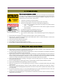
3. FIRE AND EXPLOSION
Risk of serious injuries or death
Fuels and fumes associated with generating sets can be flammable and potentially explo-
sive. Proper care in handling these materials can dramatically limit the risk of fire or explo-
sion. However, safety dictates that fully charged BC and ABC fire extinguishers are kept on
hand. Personnel must know how to operate them.
• The acids in the battery can cause explosion.
• Avoid any contact between the tools and the terminals in the battery.
• Never use metallic objects on the neck or hands when handling the set.
• Never connect the negative terminal from the battery to the positive terminal
from the starter.
• Don’t smoke or allow sparks, flames or other sources of ignition around the
fuel or batteries.
• Use adequate equipment to take fuel from the set.
• Never test the battery by touching together the terminals.
• Ensure the generating set room is properly ventilated.
• Don’t touch the battery charger or the connections during the battery charging proc-
ess.
• Always disconnect the negative terminal from the battery before to start any work on the unit.
• Keep the room, the floor and the generating set clean. When spills of fuel, oil, battery electrolyte or coolant occur
they should be cleaned up immediately.
• Never store flammable liquids near the engine.
• Store oily rags in covered metal containers.
• Avoid refilling the fuel tank while the engine is running.
• Do not attempt to operate the generating set with any known leaks in the fuel system.
4. INSTALLATION, HANDLING AND TOWING
• Make electrical connections in compliance with relevant electrical codes, standards or other requirements. This in-
cludes requirements for grounding and ground/earth faults.
• For stationary generating sets with remote fuel storage systems, make sure such systems are installed in compliance
with relevant codes, standards or other requirements.
• Engine exhaust emissions are hazardous to personnel. The exhaust for all indoor generating sets must be piped out-
doors via leak-free piping in compliance with relevant codes, standards and other requirements. Ensure hot exhaust
silencers, piping and turbochargers, if equipped, are clear of combustible material and are guarded for personnel
protection per safety requirements. Ensure that fumes from the exhaust outlet will not be hazard.
• Never lift the generating set by attaching to the engine or alternator lifting lugs. Use a sling with a “spreader bar”
connected to the base frame.
• Ensure the lifting rigging and supporting structure is in good condition and has capacity suitable for the load.
• Keep all personnel away from the generating set when it is suspended.
• Make sure all personnel are out of the generating set canopy or container, if equipped, before closing and latching
enclosure doors.
• When towing a mobile generating set, observe all codes, standards or other regulations and traffic laws. These in-
clude those regulations specifying required equipment and maximum and minimum speeds. Ensure brakes, if fitted,
are in good order.
• Do not permit personnel to ride in or on the mobile generating set. Do not permit personnel to stand or ride on the
drawbar or to stand or walk between the generating set and the towing vehicle.
• Do not install or use the generating set in any classification of hazardous environment unless it has been specifically
designed for that environment.

AR-EXP-CUMMINS-07-00 OWNERS MANUAL
Page 7
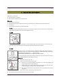
5. MECHANICAL
The generating set is designed with guards for protection from moving parts. Care
must still be taken to protect personnel and equipment from other mechanical
hazards when working around the generating set.
• Do not attempt to operate the generating set with safety guards removed.
While the generating set is running do not attempt to reach under or
around the guards to do maintenance or for any other reason.
• Keep hands, arms, long hair, loose clothing and jewellery away from pul-
leys, belts and other moving parts.
Attention!! Some moving parts con not be seen clearly when
the set is running.
• Keep access doors on enclosures, if equipped, closed and locked when not
required to be open.
• Avoid contact with hot oil, hot coolant, hot exhaust gases, hot surfaces and
sharp edges and corners.
• Wear protective clotting including gloves and hat when working around the generating set.
• Do not attempt to remove the radiator filler cap until the coolant has cooled. Then loosen the cap slowly to relive any
excess pressure before removing the cap completely.
• Ethyl ether starting aids must not be used on engines with combustion air preheating devises. These starting aids will
reduce the efficient working life of the engine.
6. CHEMICAL
Fuels, oils coolants, lubricants and battery electrolyte used in this generating set
are typical of the industry. However they can be hazardous to personnel if not
treated properly.
• Do not swallow or have skin contact with fuel, oil, coolant, lubricants and
battery electrolyte. If swallowed, seek medical treatment immediately. Do
not induce vomiting if fuel is swallowed. For skin contact, wash with soap
and water.
• Do not wear clothe that has been contaminated by fuel or lube oil.
• Wear an acid resistant apron and face shield or goggles when servicing
the battery. If electrolyte is spilled on skin or clotting, flush immediately
with large quantities of water.
• Always keep good ventilation when the equipment is working. Carbon
Monoxide inhalation cause death. Always maintain inspection routine of
the exhaust system.

AR-EXP-CUMMINS-07-00 OWNERS MANUAL
Page 8
7. NOISE
Generating sets that are not equipped with sound attenuating enclosures can produce
noise levels in excess of 105 dBA. Prolonged exposure to noise levels above 85 dBA is
hazardous to hearing.
• Ear protection must be worn when operating or working around an operating
set.
8. ELECTRICAL
Safe and efficient operation of electrical equipment can be achieved only if the equip-
ment is correctly installed, operated and maintained.
• The generating set must be connected to the load only by trained and quali-
fied electricians who are authorized to do so, and in compliance with rele-
vant electric codes, standards and other regulations.
• Ensure the generating set, is effectively grounded/earthed in accordance
with all relevant regulations prior operation.
• The generating sets should be shutdown with the battery negative (-) termi-
nal disconnected prior to attempting to connect or disconnect load connec-
tions.
• Do not attempt to connect or disconnect load connections while standing in
water or on wet or soggy ground.
• Do not touch electrical energized parts of the generating set and/or inter-
connecting cables or conductors with any part of the body or with any non
insulated conductive object.
• Place the control panel cover as soon as connection or disconnection of the
load cables is complete. Do not operate the generating set without the
cover securely on place.
• Connect the generating set only to loads and/or electrical systems that are com-
patible with it’s electrical characteristics and that are within it’s rated capacity.
• Be sure all power is disconnected from the electrical equipment being serviced.
• Keep all electrical equipment clean and dry. Replace any wiring where the insulation is cracked, cut, abraded or oth-
erwise degraded. Replace terminals that are worm, discolored or corrode. Keep terminals clean and tight.
• Insulate all connections and disconnected wires.
• Use only class BC or Class ABC extinguishers on electrical fires.

AR-EXP-CUMMINS-07-00 OWNERS MANUAL
Page 9
9. FIRST AID FOR ELECTRIC SHOCK
Identification / look out for:
• Unconsciousness and Burns
• Establish site of entry and exit of electric shock
What to do:
• Switch off the main switch.
• Break the contact between electrical source and patient using dry non-conductive object like wooden stick.
• Call for help.
• If breathing and heartbeat has stopped begin CPR
1. CALL
Check the victim for unresponsiveness. If there is no response, Call 911 and return to the victim. In most locations
the emergency dispatcher can assist you with CPR instructions.
2. BLOW
Tilt the head back and listen for breathing. If not breathing normally, pinch nose and cover the mouth with yours
and blow until you see the chest rise. Give 2 breaths. Each breath should take 1 seconds.
3. PUMP
If the victim is still not breathing normally, coughing or moving, begin chest compressions.
Push down on the chest 11/2 to 2 inches 30 times right between the nipples. Pump at the
rate of 100/minute, faster than once per second.
CONTINUE WITH 2 BREATHS AND 30 PUMPS UNTIL HELP ARRIVES.
In unconscious patient with intact breathing and pulse recovery position ensures the preven-
tion of tongue falling back and blocking the airway.
What to do:
• Place the patient on their back.
• Lift the chin to ensure the air way is open.
• Patient's arm on your side should be positioned so as to make a right angle with his
body, with elbow bent and palm facing out.
• Patient's other arm on opposite side should be placed across the chest, with back
of their hand against the cheek on your side of the patient.
• Pull up the patient's knee joint (side away from you) as it bends with the foot flat on
the ground.
• Roll over the patient in this position towards your side.
• By tilting the patient's head back ensure that the airway is open.

AR-EXP-CUMMINS-07-00 OWNERS MANUAL
Page 10
10. SPECIAL CONSIDERATIONS FOR BATTERY
CAUTION – The electrolyte is a dilute sulfuric acid that is harmful to the skin
and eyes. It is electrically conductive and corrosive. The following procedures are
to be observed:
1) Wear full eye protection and protective clothing,
2) Where electrolyte contacts the skin, wash it off immediately with water,
3) Where electrolyte contacts the eyes, flush thoroughly and immediately with water and
seek medical attention, and
4) Spilled electrolyte is to be washed down with an acid neutralizing agent. A common
practice is to use a solution of one pound (500 grams) bicarbonate of soda to one gallon
(4 liters) of water. The bicarbonate of soda solution is to be added until the evidence of
reaction (foaming) has ceased. The resulting liquid is to be flushed with water and the
area dried.
CAUTION – Lead-acid batteries present a risk of fire because they generate
hydrogen gas. The following procedures are to be followed:
1) DO NOT SMOKE when near batteries,
2) DO NOT cause flame or spark in battery area, and
3) Discharge static electricity from body before touching batteries by first touching a
grounded metal surface.

AR-EXP-CUMMINS-07-00 OWNERS MANUAL
Page 11
GENERATING SET
INSTALLATION

AR-EXP-CUMMINS-07-00 OWNERS MANUAL
Page 12
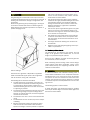
1. LOCATION
The generating set sub base tank or frame (if it’s the case)
is specifically designed for ease of moving the set. Improper
handling can cause serious damage to the generator and
components.
Never lift the generating set by attaching lugs to the engine
or alternator. Shackles and chains of suitable length and
lifting capacity must be used. A spreader bar is required to
prevent damaging the set.
See the drawings:
The location for a generator is dependent on applicable
codes and associated support systems for the generator
such as ventilation, wiring, fuel, and exhaust.
The following factors should be considered:
• The ideal location for any generator is away from ex-
treme ambient temperatures and where the generator
is protected from adverse weather conditions. It is
recommended that generator be as close to the load it
is supporting as possible.
• The structure where the Generator Set will be set upon
must be strong enough to support the weight of the
Gen-Set, its' auxiliary equipment, and other equipment
mounted on the structure.
• The structure must meet a 1 hour non-combustion fire
rating.
• The installation site must be clean, dry and not subject
to flooding.
• Because of excessive ambient temperatures associ-
ated with the use of stand-alone metal sheds from
exposure to sunlight, a concrete pad with a supported
roof and an outside security enclosure (fence) to pro-
tect the unit from vandalism, birds, rodents, and other
small animals is recommended.
• The Gen-Set generates heat while running. Installing
the Gen-Set in a tightly enclosed building or shed is not
recommended. The site must provide for adequate
cooling and ventilation with a minimum of duct work.
Adequate ventilation for a generator is specified in
cubic feet per minute.
• The site must permit engine exhaust gases to be piped
away to an area that is uninhabited by people or ani-
mals. Care must be given to ensure that exhaust gases
do not re-enter an occupied area.
• The outside site must provide access to the generator
to allow for maintenance, service, and repair. A three
foot (.914 meter) service clearance around the unit is
recommended.
• Fuel supply and ease of refueling must be taken into
consideration.
• Adequate normal and emergency lighting must be pro-
vided in any installation.
1.1. GROUND/FLOOR LOADING
The foundation for the generator must support the total
weight of the generator. This includes fuel, oil, and the
weight of any associated support systems.
Plan for 3 feet (1 Meters) of access around the generator
for maintenance, service and repair.
When calculating the floor loading, ensure the fuel weight,
cooling system fluids (where applicable), piping, pumps,
power cables/runways and supporting structures are in-
cluded in the calculations.
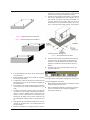
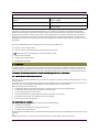
2. MOUNTING
A concrete foundation with anchored mounting bolts, is
recommended. Steel Beams are an acceptable alternative.
Foundations help in the servicing and repair of Gen-Set's
and protect the unit from moisture that could occur from
seepage. The concrete base that the generator is mounted
to should be separate and independent from the surround-
ing structure.
The following applies to concrete bases:
A Single (See Figure 1)or Double (See Figure 2) pedestal
base may be used. A height of at least 6 inches higher than
floor level is recommended.

AR-EXP-CUMMINS-07-00 OWNERS MANUAL
Figure 1- Single Pedestal Concrete Mount
Figure 2 - Double Pedestal Concrete Mount
• A double pedestal base allows easier cleaning under
most generator's.
• Double pedestals provide better access for inspecting
for oil or fuel tank leaks.
• The generator should be retained to the pedestal base
with fasteners that are recommended by the generator
set manufacturer.
• The concrete base should extend beyond the genera-
tor's "Footprint" by at least 12 Inches (305 mm) on all
sides.
• The higher the mounting base is made, the easier the
unit will be to work on when performing maintenance,
service, or repairs. Typically bases are required to be
raised at least 6 inches (153 mm) above floor level.
Placing the unit higher than 6 inches sometimes has
the advantage of making it easier to change the unit's
oil.
• Passing fuel lines and electrical conduit for a "stub-up"
through the concrete base is a standard practice of
gen-set installers.
• Concrete foundations are typically mixed by volume.
The typical ratio of cement, sand, and aggregate is
1:2:3 with a maximum 4 inch (102 mm) slump and 28
day compressive strength of 2500 psi (173 kPa).
• A generator can typically be mounted to a combustible
floor or roof, dependent upon code, however, the sur-
face beneath the engine and beyond the engine to a
minimum distance of 12 inches (305 mm) must be
covered with a non combustible insulation and a mini-
mum of 24 gage sheet metal between the insulation
and the generator. See Figure 3.
Figure 3. Combustible Floor and Roof
• Optional vibration isolators beyond those already built
in the generator also help reduce transmitted noise,
however, it is recommended that one verify that the
generator manufacturer recommends the use of an
isolator.
• Insulation must be a non-combustible material, typi-
cally a Fiberglas mat.
3. VENTILATION
3.1. OUTDOOR INSTALLATIONS - AIR COOLED UNITS
If your generator is expected to be in temperatures lower
than -20
o
F(-29
o
C) a cold weather package may be required.
The following general rules apply:
• Where strong prevailing winds are anticipated, face the
engine end away from the wind.
• Plan the installation carefully to prevent the cooling air
vents on the generator from becoming clogged by
leaves, grass, snow, etc.
Page 13

AR-EXP-CUMMINS-07-00 OWNERS MANUAL
Page 14
4. ELECTRICAL SYSTEM
There are a number of different generator systems and
typical loads in the context of electrical systems. Most sys-
tems, unless they contain automated switch gear, have a
means of disconnect between the generator and the
load. This is typically a transfer switch or discon-
nect. Ensure the contacts on the switch are rated for the
size of your system.
4.1. GENERAL ELECTRICAL SYSTEM
When mounting electrical panels, a 3 foot clearance is re-
quired and the use of an emergency light to illuminate the
unit during operation is typically required. Power for the
emergency light should be from both the primary utility and
the generator. This is highly recommend so that in the event
of a malfunction there is a light source to see to work on the
unit. Refer to your local building and electrical codes to
ensure compliance.
4.2. CONDUCTOR SIZING CONNECTION
This information is dependent upon your generator output
and intended load. When connecting cables to the genera-
tor, make connections at the generator first. Make the con-
nections at the load last. Failure to do so may constitute a
fire or safety hazard.
All ampacities are typically calculated at 75
o
C (Celsius)
(167
o
F(Fahrenheit) in the conductor size charts. Building
wire conductors should be rated at 90
o
C(194
o
F) to allow for
different ambient temperatures that these conductors may
pass through.
All conductors are typically required by electrical code to be
copper. The recommended conductor sizes are based on
maximum current. Ampacities are found in NEC Article 310,
Table 310-16. Conductor resistances are found in NEC Ta-
ble 8 "Conductor Properties".
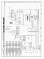
4.3. CONNECTING THE GENERATOR
Please the refer to the electrical drawing of the unit and
your transfer switch documentation for information related.
Leave the installation only to a trained personnel and don’t
forget to observe the local laws and permit requirements.
Errors during the installation may damage the equipment
and electrical devices connected to the unit and may create
fire and electrocution risks.
5. EXHAUST SYSTEM
5.1. GENERAL (EXHAUST SYSTEM)
Generator engines give off deadly carbon monoxide gas
through their exhaust systems.
Carbon monoxide gas, if breathed in sufficient concentra-
tions, can cause unconsciousness or death. Exhaust gases
must be piped safely away from any room or enclosure that
houses a generator and to a well ventilated area where
people will not be endangered.
Besides the possibility of carbon monoxide poisoning, ex-
haust piping becomes extremely hot during operation and
remains hot for a long time after shutdown. For that reason,
the following precautions are necessary:
• Avoid contact with hot engines, exhaust manifolds,
exhaust piping and mufflers. Any of these can cause
severe burns.
• Where piping must pass through combustible walls or
ceilings, special precautions must be taken to prevent
fire or heat damage such as using heat thimbles
through walls and ceilings.
5.2. GENERAL RULES FOR EXHAUST SYSTEM
When installing an exhaust system for a generator, the fol-
lowing rules should be considered:
• Exhaust piping should be of wrought iron or steel hav-
ing adequate strength and durability.
• Exhaust fittings may be of cast iron. A 9 inch spacing
(10 inches (250mm) recommended) from the exhaust
pipe and walls is also required by most local codes.
• Low points in horizontal runs of piping should be pro-
vided with condensation traps, as well as condensation
drains.
• Piping and mufflers must be properly supported and
connected.
• A flexible length of exhaust pipe is required between
the engine exhaust manifold and rigid exhaust piping.
• Exhaust piping must be terminated safely outside a
structure that houses a generator, in such a way that
hot gases and sparks will be discharged harmlessly
and will not blow against any combustible surface or
material.
• Exhaust piping must not terminate under loading plat-
forms, structures, or near any opening in a building.
• Where necessary, exhaust piping must be guarded
and/or insulated to prevent burns.
• Provide a clearance of at least 9 inches (229mm)(10
inches (250mm) recommended) between exhaust
piping and any combustible material.
• Keep exhaust piping well clear of fuel tanks, fuel lines,
etc.
5.3. RAIN CAP
A rain cap is recommended on the end of the exhaust pipe.
The rain cap is attached to the end of the pipe and opens
due to the pressure from the exhaust discharge force. The
rain cap protects the exhaust system from the environment
when the system is not running.
5.4. SPARK ARRESTOR
Use of a spark arrestor is required by the U.S. Department
of Forestry if located on lands under their jurisdiction. The
spark arrestor is recommended in areas where combustible
materials may ignite such as dry grass, leaves, or other
combustible materials.

AR-EXP-CUMMINS-07-00 OWNERS MANUAL
Page 15
6. INSTALLATION CHECKLIST BATTERY INSTALLATION
Battery is connected properly.
Recommended battery is installed.
Cables are clean and tight.
Terminals are coated with anti-corrosion grease, and
terminal covers are positioned.
FUEL SYSTEM
Complies with local and NFPA codes.
Fuel is connected and checked for leaks.
Correct fuel pressure (11-14 inches of water (0.6 psi) at
all load ranges).
Load block adjusted for maximum power for natural gas
fuel.
LOCATION
Unit is fastened to the appropriate mounting pad.
Louvers are free from obstruction.
Exhaust is clear of flammable objects and debris.
ELECTRICAL CONNECTIONS
Complies with local code requirements and all National
Electrical Codes.
Utility is connected and present.
Transfer switch is connected.
All wires running outside of the generator are in NEC-
approved conduit. *Note: Utility wires and transfer switch
control wires must be in separate conduit.
Unit is grounded to an approved earth ground.
COOLING AND VENTILATING
All inlets and outlets are free from obstruction.
OTHER
Verify that the unit is filled to the proper level with the
proper break-in oil. Adjust as required.

AR-EXP-CUMMINS-07-00 OWNERS MANUAL
Page 16

AR-EXP-CUMMINS-07-00 OWNERS MANUAL
Page 17
GENERATING SET
OPERATION AND
MAINTENANCE

AR-EXP-CUMMINS-07-00 OWNERS MANUAL
Page 18
6. PRE-OPERATION CHECK
Before starting, complete the following:
1. Set the generator's Start/stop switch to the
Stop position.
2. Turn OFF the utility power supply to the transfer
switch using the means provided (such as the
utility main line circuit breaker).
3. Check the engine crankcase oil level and, if necessary,
fill to the dipstick FULL mark with the recommended
oil. Do not fill above the FULL mark.
4. Check the fuel supply. All fuel shutoff valves in the fuel
supply lines must be open.
Never operate the engine with the oil level
below the “Add” mark on the dipstick. Doing
this could damage the engine.
6.1. Electrical Checks.
Complete electrical checks as follows:
1. Turn on the utility power supply to the transfer switch
using the means provided (such as a utility main line circuit
breaker).
The transfer switch is now electrically “hot.”
Contact with “hot” parts will result in extremely
hazardous and possibly fatal electrical shock.
Proceed with caution.
2. Use an accurate AC voltmeter to check utility power
source voltage across terminals.
3. Check utility power source voltage across terminals and
the transfer switch neutral lug; then across second terminal
and neutral. Nominal line-to neutral voltage should be 120
volts AC.
4. When certain that utility supply voltage is compatible with
transfer switch and load circuit ratings, turn OFF the utility
power supply to the transfer switch.
5. Set the generator's main circuit breaker to its OFF (or
open) position. Initial tests will be conducted at no-load
condition.
6. On the generator panel Start/stop switch to the to start
position The engine should crank and start when the re-
mote start input is activated.
7. Let the engine warm up for about five minutes to
allow internal temperatures to stabilize. Then, set
the generator’s main circuit breaker to its ON (or closed)
position.
Proceed with caution! Generator power voltage
is now supplied to the transfer switch. Contact
with live transfer switch parts will result in
dangerous and possibly fatal electrical shock.
8. Connect an accurate AC voltmeter and an AC frequency
meter across transfer switch terminal lugs and voltage and
frequency of the unit must be accord to the specifications
of the generator.
9. Connect the AC voltmeter test leads across terminal
Lugs and neutral, one by one.
10. Set the generator’s main circuit breaker to its OFF (or
open) position. Let the engine run at no load for a few min-
utes to stabilize internal engine generator temperatures.
11. Set the generator's Start/stop switch to stop position.
The engine should shut down.
NOTE:
It is important that you DO NOT proceed until you are cer-
tain that generator AC voltage and frequency are correct
and within the stated limits. Generally, if both AC frequency
and voltage are high or low, the engine governor requires
adjustment. If frequency is correct, but voltage is high or
low, the generator’s voltage regulator requires adjustment.
6.2. GENERATOR TESTS UNDER LOAD
To test the generator set with electrical loads applied, pro-
ceed as follows:
1. Set generator’s main circuit breaker to its OFF (or open)
position.
2. Set the generator's Start/stop switch to OFF.
3. Turn OFF the utility power supply to the transfer switch,
using the means provided (such as a utility main line circuit
breaker).
Do not attempt manual transfer switch operation
until all power voltage supplies to the transfer
switch have been positively turned off. Failure to
turn off all power voltage supplies will result in
extremely hazardous and possibly fatal electrical
shock.
4. Manually set the transfer switch to the STANDBY posi-
tion, i.e., load terminals connected to the generator's termi-
nals. The transfer switch operating lever should be down.
5. Set the generator's Start/stop switch to MANUAL. The
engine should crank and start immediately.
6. Let the engine stabilize and warm up for a few minutes.
7. Set the generator’s main circuit breaker to its ON (or
closed) position. Loads are now powered by the standby

AR-EXP-CUMMINS-07-00 OWNERS MANUAL
Page 19
generator.
8. Turn ON electrical loads. Apply an electrical load equal to
the full rated wattage/amperage capacity of the installed
generator.
9. Connect an accurate AC frequency meter across terminal
lugs . Voltage should be +/- 1.5% of the specificated, and
frequency +/- 4.0% of the specificated on the unit.
10. Let the generator run at full rated load for 20-30 min-
utes. Listen for unusual noises, vibration or other indica-
tions of abnormal operation. Check for oil leaks, evidence of
overheating, etc.
11. When testing under load is complete, turn OFF electrical
loads.
12. Set the generator's main circuit breakers to their OFF
(or open) positions.
13. Let the engine run at no-load for a few minutes.
14. Set the Start/stop switch to stop. The engine should
shut down.
6.3. CHECKING AUTOMATIC OPERATION
To check the system for proper automatic operation, pro-
ceed as follows:
1. Check that the Start/stop switch is set to stop.
2. Manually set the transfer switch to the UTILITY position,
i.e., load terminals connected to the utility power source
side.
3. Turn ON the utility power supply to the transfer switch,
using the means provided (such as a utility main line circuit
breaker).
4. Set the Start/stop switch to manual. The engine should
crank and start when the remote start input is activated.
5. Turn OFF the utility power supply to the transfer switch.
With the Start/stop switch at AUTO, the engine should crank
and start when the utility source power is turned OFF. After
starting, the transfer switch should connect load circuits to
the standby side. Let the system go through its entire auto-
matic sequence of operation.
With the generator running and loads powered by generator
AC output, turn ON the utility power supply to the transfer
switch. The following should occur:
• After about six seconds, the switch should transfer
loads back to the utility power source.
• About one minute after retransfer, the engine should
shut down.
Check the installation and application data charts for any
additional information.

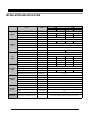
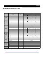
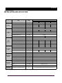
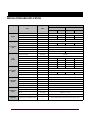
AR-EXP-CUMMINS-07-00 OWNERS MANUAL
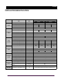
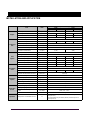
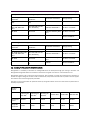
Item Units
Type of Operation and Application
60 Hz 50 Hz
Prime Standby Prime Standby
Engine
Rated Speed rpm 1800 1500
Gross Engine Output bhp (kWm) 90 (67) 99 (74) 77 (58) 85 (64)
BMEP psi (kPa) 165 (1137) 182 (1255) 169 (1165) 187 (1289)
Mean Piston Speed Ft/s (m/s) 23.6 (7.2) 19.66 (6.0)
Cooling Sys-
tem
Ambient Air Temperature °F (°C) 122 (50)
Engine Heat Reject to Coolant BTU/min (kW) 2035 (35.8) 2240 (39.3) 1750 (30.8) 1995 (35.0)
Coolant Capacity Gal (L) 1.9 (7.2)
Standard Thermostat Range °F (°C) 180-203 (82-95)
Maximum Pressure Cap Psi (kpa) 10 (69)
Maximum coolant friction Psi (kpa) 5 (35) 4 (28)
Fuel
System
Total drain flow gal/h (L/h) 8 (30)
Fuel Type Diesel #2
Fuel Consumption @ 25% Power gal/hr (L/hr)
1.08 1.19 0.94 1.04
Fuel Consumption @ 50% Power gal/hr (L/hr)
2.15 2.37 1.89 2.08
Fuel Consumption @ 75% Power gal/hr (L/hr)
3.23 3.56 2.83 3.12
Fuel Consumption @ 100% Power gal/hr (L/hr)
4.31 4.74 3.77 4.17
Air Require-
ment
Combustion Air Flow ft
3
/min (L/s) 194 (92) 197 (93) 141 (66) 145 (68)
Air Intake Restriction clean filter In.H
2
O (kPa) 10(2.49)
Air Intake Restriction dirty filter In.H
2
O (kPa) 25 (6.22)
Exhaust Temperature °F (°C) 886 (475) 934 (501) 974 (523) 1035 (557)
Maximun Allowable Back Pressure In.H
2
O (kPa) 3 (10.13)
Lubrication
System
Maximum oil temperature °F (°C) 250 (121)
Oil Pan Capacity gal (L) 2.5 (9.5)
Total Engine Oil Cap. w/filter gal (L) 2.88 (10.9)
Oil Filter Type Cartridge
Lube oil specifications grade SAE 15W - 40
Engine Elec-
tricals
Battery Charging Alternator Volts, Ground 12V, negative
Baterry Charging Alternator Rated amps 45
Recommended Battery Cold
Crank
CCA amps 600
Starter Motor Volts, Ground 12V, negative
Operation
Temperature and Altidtude Losses % 4% per 1000 ft (300 m) and 1% per 10°F (2% per 11°C)
ACUM65
INSTALLATION AND APPLICATION
Page is loading ...
Page is loading ...
Page is loading ...
Page is loading ...
Page is loading ...
Page is loading ...
Page is loading ...
Page is loading ...
Page is loading ...
Page is loading ...
Page is loading ...
Page is loading ...
Page is loading ...
Page is loading ...
-
 1
1
-
 2
2
-
 3
3
-
 4
4
-
 5
5
-
 6
6
-
 7
7
-
 8
8
-
 9
9
-
 10
10
-
 11
11
-
 12
12
-
 13
13
-
 14
14
-
 15
15
-
 16
16
-
 17
17
-
 18
18
-
 19
19
-
 20
20
-
 21
21
-
 22
22
-
 23
23
-
 24
24
-
 25
25
-
 26
26
-
 27
27
-
 28
28
-
 29
29
-
 30
30
-
 31
31
-
 32
32
-
 33
33
-
 34
34


Armstrong ACUM65 User manual
- Category
- Power generators
- Type
- User manual
Ask a question and I''ll find the answer in the document
Finding information in a document is now easier with AI
Related papers
Other documents
-
CUMMINS QD 3200 HDZAA User manual
-
Simplicity 040491-00 User manual
-
Vetus GHX_GLX50_60 Hz User manual
-
-
Kohler DIESEL10LC User manual
-
Hyundai power products 1500RPM Diesel Generator Owner's manual
-
Hyundai DHY15000SE(-3) User manual
-
-
-
Anova GC5500TFE Owner's manual