Page is loading ...

© 2011-2016 Tyco Fire Protection Products. Specifications and other information shown were current as of publication and are subject to change without notice.
TYCO, SIMPLEX, and the product names listed in this material are marks and/or registered marks. Unauthorized use is strictly prohibited.
579-977
Rev. C
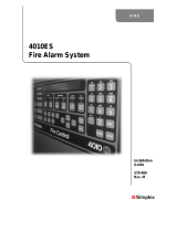
Introduction The 4606-9102 Liquid Crystal Display (LCD) Annunciator for the 4010ES provides remote
annunciation of the Fire Alarm Control Unit (FACU) status, see Figure 1. Visual status is
provided using an LCD and LEDs. Audible annunciation is provided using a piezo sounder. Use
the keyswitch to lock or enable the annunciator switch.
Figure 1. 4606-9102 LCD Annunciator
In this
publication
FIRE
ALARM
PRIORITY 2
ALARM
SYSTEM
SUPERVISORY
SYSTEM
TROUBLE
POWER
ON
ALARM
SILENCED
ALARM
ACK
ALARM
ACK
SUPV
ACK
TBL
ACK
ALARM
SILENCE
SYSTEM
RESET
DISPLAY
TIME
Topic Page
Specifications 2
Installing the 4606-9102 LCD Annunciator 2
Address chart 4
General wiring precautions 7
Specific wiring precaution 7
Wire length tables 7
Checkout procedure 8
Cautions
and warnings
READ AND SAVE THESE INSTRUCTIONS - Follow the instructions in this installation manual. These instructions
must be followed to avoid damage to this product and associated equipment. Product operation and reliability depend
upon proper installation.
DO NOT INSTALL ANY SIMPLEX® PRODUCT THAT APPEARS DAMAGED - Upon unpacking your
Simplex product, inspect the contents of the carton for shipping damage. If damage is apparent, immediately file a claim
with the carrier and notify an authorized Simplex product supplier.
ELECTRICAL HAZARD - Disconnect electrical field power when making any internal adjustments or repairs. All
repairs should be performed by a representative or authorized agent of your local Simplex product supplier.
STATIC HAZARD - Static electricity can damage components. Handle as follows:
• Ground yourself before opening or installing components.
• Prior to installation, keep components wrapped in anti-static material at all times.
EYE SAFETY HAZARD - Under certain fiber optic application conditions, the optical output of this device may exceed
eye safety limits. Do not use magnification (such as a microscope or other focusing equipment) when viewing the output
of this device.
SULFURIC ACID WARNING - Battery contains sulfuric acid, which can cause severe burns to the skin and eyes and
can destroy fabric. Replace any leaking or damaged battery while wearing appropriate protective gear. If you come in
contact with sulfuric acid, immediately flush skin or eyes with water for 15 minutes and seek immediate medical attention.
4606-9102 for 4010ES LCD
Annunciator installation instructions

2
Specifications
• Communication wiring is supervised and power-limited.
• 24V power wiring supplied by a 4010ES FACU is power-limited.
• If the interconnected control unit is not used to provide operating power to the annunciator, a
regulated UL-listed 24VDC power supply for fire protective signaling is required.
• A minimum 18 AWG Twisted pair wiring is required for communications. If twisted-
shielded pair wire is used, ground the shield at the main panel only.
• Connect a dedicated earth ground connection to the back box, in accordance with NFPA 70,
Article 250.
Flush mount 4606-9102 LCD Annunciators
• In masonry walls, use a Steel City GW-635-G (3½ in/89mm deep) masonry box, or an
equivalent box.
• In plasterboard walls, use six listed gangable switch boxes, RACO 590 (3½ in/89mm deep),
RACO 600 (2½ in/63.5mm deep), RACO 601 (3½ in/89mm deep), or an equivalent box.
Surface mount 4606-9102 LCD Annunciators
• Use a 2975-9206 box (2¾ in/69.85mm deep) or a 2975-9217 box (1¾ in/44.75mm deep).
Installing the
4606-9102 LCD
Annunciator
Complete the following steps to install the 4606-9102 LCD Annunciator:
1. Terminate the annunciator’s communication (COMM) and power lines as shown in Figure 2.
Figure 2. Terminating the COMM and Power Lines
2. Connect the ground harness to earth ground.
Note: To prevent Electrostatic Discharge (ESD), use a wrist strap assembly that connects to ground. Ensure
the power is OFF before installing or servicing the annunciator.
Table 1: Power requirements and environmental limitations
Voltage 24VDC Power Supply. 24VDC Nominal/18VDC minimum.
Current Maximum Current Draw. with LCD Backlight OFF at 24VDC: 65mA.
Maximum Current Draw. with LCD Backlight ON at 24VDC: 110mA.
Maximum Current Draw. with LCD Backlight ON and Piezo ON at 18VDC: 140mA.
Temperature Operating Range. 32°F to 120°F (0°C to 49°C).
Humidity The equipment operates normally under non-condensing humidity conditions up to 93%,
relative humidity at 100°F (38°C).
4 3 2 1
24V
24C (0V)
TB2
6 5 4 3 2 1
TB1
- COMM
+ COMM
SHIELD
TB2-1 to 24C of next annunciator.
TB2-2 from 24C of FACU power
supply or previous annunciator.
TB2-3 to 24V of next annunciator.
TB2-4 from 24V of FACU power
supply or previous annunciator.
TB1-1 SHIELD to next annunciator.
TB1-2 SHIELD from FACU or previous annunciator.
TB1-3 +COMM to next annunciator.
TB1-4 +COMM from FACU or previous annunciator.
TB1-5 -COMM to next annunciator.
TB1-6 -COMM from FACU
or previous annunciator.
4606-9102 LCD Annunciator installation instructions

3
Installing the
4606-9102 LCD
Annunciator
Figure 3. Power and RUI Communicating Wiring to TB1 and TB2
3. Using switch SW2 (see Figure 4), set the annunciator’s address in accordance
with Table 2. Switches SW2-1 through SW2-7 set the annunciator’s address, and switch SW2-8
sets the annunciator’s baud rate.
SW2-8 OFF or OPEN = 1200 Baud.
SW2-8 ON or CLOSED = 9600 Baud.
Figure 4. DIP switch SW2
Continued on the next page.
24C (0V)
+24VDC
24C (0V)
+24VDC
TB1
TB2
-COMM (RUI-)
+COMM (RUI+)
SHIELD
SHIELD
+COMM (RUI+)
-COMM (RUI-)
GROUND HARNESS
733-936
ON
Note: DIP switch SW2
is located at the bottom of the
electronics assembly.
Position of 3 shown
in OFF position.
Example depicts:
Address = 4
Baud Rate = 9600
4606-9102 LCD Annunciator installation instructions

4
Address chart
Table 2: Address chart
SW2-1 SW2-2 SW2-3 SW2-4 SW2-5 SW2-6 SW2-7 ADDRESS
OFF ON ON ON ON ON ON = ADDRESS 1
ON OFF ON ON ON ON ON = ADDRESS 2
OFF OFF ON ON ON ON ON = ADDRESS 3
ON ON OFF ON ON ON ON = ADDRESS 4
OFF ON OFF ON ON ON ON = ADDRESS 5
ON OFF OFF ON ON ON ON = ADDRESS 6
OFF OFF OFF ON ON ON ON = ADDRESS 7
ON ON ON OFF ON ON ON = ADDRESS 8
OFF ON ON OFF ON ON ON = ADDRESS 9
ON OFF ON OFF ON ON ON = ADDRESS 10
OFF OFF ON OFF ON ON ON = ADDRESS 11
ON ON OFF OFF ON ON ON = ADDRESS 12
OFF ON OFF OFF ON ON ON = ADDRESS 13
ON OFF OFF OFF ON ON ON = ADDRESS 14
OFF OFF OFF OFF ON ON ON = ADDRESS 15
ON ON ON ON OFF ON ON = ADDRESS 16
OFF ON ON ON OFF ON ON = ADDRESS 17
ON OFF ON ON OFF ON ON = ADDRESS 18
OFF OFF ON ON OFF ON ON = ADDRESS 19
ON ON OFF ON OFF ON ON = ADDRESS 20
OFF ON OFF ON OFF ON ON = ADDRESS 21
ON OFF OFF ON OFF ON ON = ADDRESS 22
OFF OFF OFF ON OFF ON ON = ADDRESS 23
ON ON ON OFF OFF ON ON = ADDRESS 24
OFF ON ON OFF OFF ON ON = ADDRESS 25
ON OFF ON OFF OFF ON ON = ADDRESS 26
OFF OFF ON OFF OFF ON ON = ADDRESS 27
ON ON OFF OFF OFF ON ON = ADDRESS 28
OFF ON OFF OFF OFF ON ON = ADDRESS 29
ON OFF OFF OFF OFF ON ON = ADDRESS 30
OFF OFF OFF OFF OFF ON ON = ADDRESS 31
ON ON ON ON ON OFF ON = ADDRESS 32
OFF ON ON ON ON OFF ON = ADDRESS 33
ON OFF ON ON ON OFF ON = ADDRESS 34
OFF OFF ON ON ON OFF ON = ADDRESS 35
ON ON OFF ON ON OFF ON = ADDRESS 36
OFF ON OFF ON ON OFF ON = ADDRESS 37
ON OFF OFF ON ON OFF ON = ADDRESS 38
OFF OFF OFF ON ON OFF ON = ADDRESS 39
ON ON ON OFF ON OFF ON = ADDRESS 40
OFF ON ON OFF ON OFF ON = ADDRESS 41
ON OFF ON OFF ON OFF ON = ADDRESS 42
OFF OFF ON OFF ON OFF ON = ADDRESS 43
ON ON OFF OFF ON OFF ON = ADDRESS 44
OFF ON OFF OFF ON OFF ON = ADDRESS 45
ON OFF OFF OFF ON OFF ON = ADDRESS 46
OFF OFF OFF OFF ON OFF ON = ADDRESS 47
ON ON ON ON OFF OFF ON = ADDRESS 48
OFF ON ON ON OFF OFF ON = ADDRESS 49
ON OFF ON ON OFF OFF ON = ADDRESS 50
OFF OFF ON ON OFF OFF ON = ADDRESS 51
ON ON OFF ON OFF OFF ON = ADDRESS 52
OFF ON OFF ON OFF OFF ON = ADDRESS 53
ON OFF OFF ON OFF OFF ON = ADDRESS 54
OFF OFF OFF ON OFF OFF ON = ADDRESS 55
ON ON ON OFF OFF OFF ON = ADDRESS 56
OFF ON ON OFF OFF OFF ON = ADDRESS 57
ON OFF ON OFF OFF OFF ON = ADDRESS 58
OFF OFF ON OFF OFF OFF ON = ADDRESS 59
ON ON OFF OFF OFF OFF ON = ADDRESS 60
OFF ON OFF OFF OFF OFF ON = ADDRESS 61
ON OFF OFF OFF OFF OFF ON = ADDRESS 62
OFF OFF OFF OFF OFF OFF ON = ADDRESS 63
ON ON ON ON ON ON OFF = ADDRESS 64
4606-9102 LCD Annunciator installation instructions
Continued on the next page.

5
OFF ON ON ON ON ON OFF = ADDRESS 65
ON OFF ON ON ON ON OFF = ADDRESS 66
OFF OFF ON ON ON ON OFF = ADDRESS 67
ON ON OFF ON ON ON OFF = ADDRESS 68
OFF ON OFF ON ON ON OFF = ADDRESS 69
ON OFF OFF ON ON ON OFF = ADDRESS 70
OFF OFF OFF ON ON ON OFF = ADDRESS 71
ON ON ON OFF ON ON OFF = ADDRESS 72
OFF ON ON OFF ON ON OFF = ADDRESS 73
ON OFF ON OFF ON ON OFF = ADDRESS 74
OFF OFF ON OFF ON ON OFF = ADDRESS 75
ON ON OFF OFF ON ON OFF = ADDRESS 76
OFF ON OFF OFF ON ON OFF = ADDRESS 77
ON OFF OFF OFF ON ON OFF = ADDRESS 78
OFF OFF OFF OFF ON ON OFF = ADDRESS 79
ON ON ON ON OFF ON OFF = ADDRESS 80
OFF ON ON ON OFF ON OFF = ADDRESS 81
ON OFF ON ON OFF ON OFF = ADDRESS 82
OFF OFF ON ON OFF ON OFF = ADDRESS 83
ON ON OFF ON OFF ON OFF = ADDRESS 84
OFF ON OFF ON OFF ON OFF = ADDRESS 85
ON OFF OFF ON OFF ON OFF = ADDRESS 86
OFF OFF OFF ON OFF ON OFF = ADDRESS 87
ON ON ON OFF OFF ON OFF = ADDRESS 88
OFF ON ON OFF OFF ON OFF = ADDRESS 89
ON OFF ON OFF OFF ON OFF = ADDRESS 90
OFF OFF ON OFF OFF ON OFF = ADDRESS 91
ON ON OFF OFF OFF ON OFF = ADDRESS 92
OFF ON OFF OFF OFF ON OFF = ADDRESS 93
ON OFF OFF OFF OFF ON OFF = ADDRESS 94
OFF OFF OFF OFF OFF ON OFF = ADDRESS 95
ON ON ON ON ON OFF OFF = ADDRESS 96
OFF ON ON ON ON OFF OFF = ADDRESS 97
ON OFF ON ON ON OFF OFF = ADDRESS 98
OFF OFF ON ON ON OFF OFF = ADDRESS 99
ON ON OFF ON ON OFF OFF = ADDRESS 100
OFF ON OFF ON ON OFF OFF = ADDRESS 101
ON OFF OFF ON ON OFF OFF = ADDRESS 102
OFF OFF OFF ON ON OFF OFF = ADDRESS 103
ON ON ON OFF ON OFF OFF = ADDRESS 104
OFF ON ON OFF ON OFF OFF = ADDRESS 105
ON OFF ON OFF ON OFF OFF = ADDRESS 106
OFF OFF ON OFF ON OFF OFF = ADDRESS 107
ON ON OFF OFF ON OFF OFF = ADDRESS 108
OFF ON OFF OFF ON OFF OFF = ADDRESS 109
ON OFF OFF OFF ON OFF OFF = ADDRESS 110
OFF OFF OFF OFF ON OFF OFF = ADDRESS 111
ON ON ON ON OFF OFF OFF = ADDRESS 112
OFF ON ON ON OFF OFF OFF = ADDRESS 113
ON OFF ON ON OFF OFF OFF = ADDRESS 114
OFF OFF ON ON OFF OFF OFF = ADDRESS 115
ON ON OFF ON OFF OFF OFF = ADDRESS 116
OFF ON OFF ON OFF OFF OFF = ADDRESS 117
ON OFF OFF ON OFF OFF OFF = ADDRESS 118
OFF OFF OFF ON OFF OFF OFF = ADDRESS 119
Table 2: Address chart
SW2-1 SW2-2 SW2-3 SW2-4 SW2-5 SW2-6 SW2-7 ADDRESS
4606-9102 LCD Annunciator installation instructions

6
Installing the
4606-9102 LCD
Annunciator
4. Mount the annunciator in the back box using the two slotted screws provided, see Figure 5.
Figure 5. LCD Assembly
IMPORTANT:
- Use the holes specified in Figure 5 to install the LCD assembly.
- The trim plate covers a hole in the keyboard which provides access to the display’s
contrast adjustment potentiometer.
5. Adjust the contrast located on the lower left-end corner of the electronics assembly, see Figure
5, using a small screw driver. Turn the potentiometer and observe the LCD display until the
contrast is at the correct setting.
6. Label the user-defined labels appropriately. Pull the top of the label pocket forward and insert
the user-defined labels.
7. Using the four oval-head screws provided, mount the trim plate to the back box, see Figure 6.
Figure 6. Expanded view of 4606-9102 LCD Annunciator
Continued on the next page.
Slotted screws
part no.412-059
Contrast adjustment
Label pocket
Four oval head screws
(part no. 411-702)
LCD assembly
Back box
Two slotted screws
(part no. 412-059)
Trim plate
4606-9102 LCD Annunciator installation instruction

7
General wiring
precautions
• All wiring must be copper conductors only.
• Do not exceed the maximum wiring lengths specified in the wire length tables in this
document.
• If shielding is used:
- Maintain the metallic continuity of the shield throughout the entire length of cable.
- The entire length of the cable must have a resistance greater than 1 X 10
6
Ohms to earth
ground.
- Ensure the shield is connected to a SHIELD terminal at each annunciator, and is
terminated only at the main panel.
• Ensure underground wiring is free of water.
• Do not run wires through elevator shafts.
• Wire runs in plenums must be in a conduit unless they are rated for plenum use.
• Splicing is permitted in the following situations:
- All connections are soldered (rosin-core solder), crimped in metal sleeves, or
encapsulated with an epoxy resin.
- When using solder or crimped metal sleeves, ensure the junction is insulated with a high
grade electrical tape that equals the quality of the original insulating jacket.
- The continuity of the shield is maintained throughout the length of the cable.
• Do not run other wiring in the same conduit as system wiring.
Specific wiring
precaution
• Ensure 24V power wiring is power limited.
• Communication wiring is supervised and power limited.
• 4606-9102 LCD Annunciator wiring that leaves the building, above or below ground,
requires overvoltage suppression at both ends for the communication and the power
wiring. Communication and power wiring must meet the following requirements using:
- A Simplex Model 2081-9044 overvoltage protector (200 mA) or a Simplex Model
2081-9027 (200 mA) isolated loop circuits protector.
- Simplex Model 2081-9028 (5-amp) isolated loop circuit protector.
- For underground wiring, select the appropriate isolated loop circuit protector. Run the
circuit wiring in a separate parallel wiring trough, to separate it from any commercial
power distribution wiring.
- For overhead wiring, select the appropriate isolated loop circuit protector. The wiring is
limited to one contiguous property and the total wire length must not exceed 2500 feet
(762 meters). Run the circuit wiring on separate poles, to separate it from any poles
supporting commercial power distribution wiring. Run the wiring in parallel with direct
relation to the commercial power distribution. The separation is a minimum distance,
whichever is greater, of 100 feet (30.48 meters), or the maximum span between any two
adjacent poles of either the system’s circuit or the commercial power distribution circuit.
• For the maximum wire lengths with or without circuit protectors, see Tables 3 through 6.
Wire length
tables
Table 3 and Table 4 show the maximum wire lengths possible for the power wiring. Table 5
and Table 6 show the maximum wire lengths for the communication wiring.
Note:
• When using multiple annunciators and runs, ensure the total of all runs does not exceed 10,000 feet
(3048 meters), including T-Taps.
• The maximum number of 2081-9044 over-voltage protectors on a single communication loop is four.
The maximum number of 2081-9028 isolated loop circuit protectors on a single communication loop is
four.
Continued on the next page.
4606-9102 LCD Annunciator installation instructions

579-977
Rev. C
Wire length
tables
Communication line tables:
Checkout
procedure
When the installation is complete, verify that the remote annunciator is working correctly:
1. Verify that the LEDs and the LCD are working by turning the keyswitch OFF and then ON. This
process causes the remote annunciator to execute a self-test which checks each LED and the
LCD.
2. Verify that the annunciator communicates properly with the FACU by observing the remote
annunciator. If the annunciator is not wired properly and is not communicating with the FACU,
error messages are displayed and an audible signal is emitted. Also, a card missing trouble is
displayed at the FACU.
Note: For Programming changes, refer to the relevant panel programming manual.
Table 3: With 2081-9044 or 2081-9027 Circuit Protectors
Total Current
(Amps)
12 AWG
(3.309 mm²)
14 AWG
(2.801 mm²)
16 AWG
(1.309 mm²)
18 AWG
(0.823 mm²)
0.100 2,500ft (762m) 2,500ft (762m) 2,371ft (722.68m) 1,409ft (429.46m)
0.200 2,500ft (762m) 1,782ft (543.15m) 889ft (270.96m) 705ft (214.88m)
Table 4: Without 2081-9044 / 2081-9027 Circuit Protectors (or with 2081-9028 Circuit
Protectors)
Total
Current
(Amps)
12 AWG
(3.309 mm²)
14 AWG
(2.801 mm²)
16 AWG
(1.309 mm²)
18 AWG
(0.823 mm²)
0.100 2,500ft (762m) 2,500ft (762m) 2,500ft (762m) 2,349ft (715.97m)
0.200 2,500ft (762m) 2,500ft (762m) 1,482ft (451.71m) 1,175ft (358.14m)
0.300 2,500ft (762m) 1,980ft (603.5m) 988ft (301.14m) 783ft (238.65m)
0.400 2,361ft (719.63m) 1,485ft (452.62m) 741ft (225.85m) 587ft (178.91m)
0.500 1,889ft (575.76m) 1,188ft (362.1m) 593ft (180.74m) 470ft (143.25m)
0.600 1,574ft (479.75m) 990ft (301.75m) 494ft (150.57m) 392ft (119.48m)
0.700 1,349ft (411.17m) 849ft (258.77m) 423ft (128.93m) 336ft (102.41m)
0.800 1,181ft (359.96m) 743ft (226.46m) 371ft (113.08m) 294ft (89.61m)
0.900 1,049ft (319.73m) 660ft (201.16m) 329ft (100.27m) 261ft (79.55m)
1.000 944ft (287.73m) 594ft (181.05m) 296ft (90.22m) 235ft (71.62m)
1.100 859ft (261.82m) 540ft (164.59m) 269ft (81.99m) 214ft (65.22m)
1.200 787ft (239.87m) 495ft (150.87m) 247ft (75.28m) 196ft (59.74m)
With 2081-9027 isolated Loop Circuit Protectors
0.100 2,500ft (762m) 2,500ft (762m) 2,371ft (722.68m) 1,409ft (429.46m)
0.200 2,500ft (762m) 1,782ft (543.15m) 889ft (270.96m) 705ft (214.88m)
Table 5: With 2081-9044 or 2081-9027 Circuit Protectors
12 AWG (3.309 mm²) 14 AWG (2.801 mm²) 16 AWG (1.309 mm²) 18 AWG (0.823 mm²)
2,500ft (762m) 2,500ft (762m) 2,450ft (746.76m) 1,650ft (502.92m)
Table 6: Without 2081-9044 / 2081-9027 Circuit Protectors (or with 2081-9028 Circuit Protectors)
12 AWG (3.309 mm²) 14 AWG (2.801 mm²) 16 AWG (1.309 mm²) 18 AWG (0.823 mm²)
2,500ft (762m) 2,500ft (762m) 2,500ft (762m) 2,500ft (762m)
With 2081-9027 isolated Loop Circuit Protectors
2,500ft (762m) 2,500ft (762m) 2,450ft (746.76m) 1,650ft (502.92m)
4606-9102 LCD Annunciator installation instructions
/