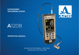
ACS A1410 PULSAR Operating instructions

Category
Cable network testers
Type
Operating instructions

ACS A1410 PULSAR is a high-performance ultrasonic pulse velocity tester designed for a wide range of applications in concrete testing. With its advanced features, it enables precise measurements of propagation time and velocity of longitudinal ultrasonic waves in concrete structures. Whether you need to assess concrete strength, locate internal flaws, or evaluate structural integrity, this instrument provides valuable insights for informed decision-making.

ACS A1410 PULSAR is a high-performance ultrasonic pulse velocity tester designed for a wide range of applications in concrete testing. With its advanced features, it enables precise measurements of propagation time and velocity of longitudinal ultrasonic waves in concrete structures. Whether you need to assess concrete strength, locate internal flaws, or evaluate structural integrity, this instrument provides valuable insights for informed decision-making.

Ultrasonic velocity tester A1410 Pulsar
Operation Manual
1
ACOUSTIC
CONTROL
SYSTEMS
ULTRASONIC PULSE
VELOCITY TESTER
Acoustic Control Systems – ACS Group
Saarbrücken, Germany 2019
A1410
PULSAR
OPERATION MANUAL
Ultrasonic velocity tester A1410 Pulsar
Operation Manual
2
ACOUSTIC
CONTROL
SYSTEMS
Ultrasonic velocity tester A1410 Pulsar
Operation Manual
3
ACOUSTIC
CONTROL
SYSTEMS
CONTENTS
1 DESCRIPTION AND OPERATION ............................................................................................................................6
1.1 Intended use ......................................................................................................................................................................................................6
1.1.1 Intended use and range of application ...............................................................................................................................6
1.1.2 Operating conditions ........................................................................................................................................................................6
1.2 Technical specifications ...........................................................................................................................................................................7
1.3 Valid international standards ............................................................................................................................................................... 8
1.4 Instrument design and operation ...................................................................................................................................................9
1.4.1 Instrument design ..............................................................................................................................................................................9
1.4.2 Operation of the instrument ..................................................................................................................................................... 10
1.4.3 Operating modes ...............................................................................................................................................................................10
1.4.4 Display .........................................................................................................................................................................................................10
1.4.5 Keyboard....................................................................................................................................................................................................13
2 INTENDED USE ..............................................................................................................................................................14
2.1 Operational restrictions ............................................................................................................................................................................14
2.2 Preparing the instrument for use ...................................................................................................................................................14
2.2.1 Surface preparation ..........................................................................................................................................................................14
2.2.2 Switching the instrument on and off. ...............................................................................................................................14
Ultrasonic velocity tester A1410 Pulsar
Operation Manual
4
ACOUSTIC
CONTROL
SYSTEMS
2.3 Intended use of the ultrasonic pulse velocity tester ........................................................................................................15
2.3.1 Setup mode ............................................................................................................................................................................................. 15
2.3.2 Digital mode ..........................................................................................................................................................................................25
2.3.3 Waveform mode ................................................................................................................................................................................. 30
2.4 Transfer data to a PC .................................................................................................................................................................................33
3 MAINTENANCE ..............................................................................................................................................................34
3.1 Battery ....................................................................................................................................................................................................................34
3.2 Charging the battery .................................................................................................................................................................................34
3.3 Possible malfunctions ..............................................................................................................................................................................34
4 STORAGE .........................................................................................................................................................................35
5 TRANSPORTATION ......................................................................................................................................................36
Ultrasonic velocity tester A1410 Pulsar
Operation Manual
5
ACOUSTIC
CONTROL
SYSTEMS
2.3 Intended use of the ultrasonic pulse velocity tester ........................................................................................................15
2.3.1 Setup mode ............................................................................................................................................................................................. 15
2.3.2 Digital mode ..........................................................................................................................................................................................25
2.3.3 Waveform mode ................................................................................................................................................................................. 30
2.4 Transfer data to a PC .................................................................................................................................................................................33
3 MAINTENANCE ..............................................................................................................................................................34
3.1 Battery ....................................................................................................................................................................................................................34
3.2 Charging the battery .................................................................................................................................................................................34
3.3 Possible malfunctions ..............................................................................................................................................................................34
4 STORAGE .........................................................................................................................................................................35
5 TRANSPORTATION ......................................................................................................................................................36
The present operation manual (hereinafter referred to as “Manual”) contains technical speci-
fications, description of the instrument and its operating principle as well as information neces-
sary for correct operation of the ultrasonic pulse velocity tester A1410 (hereinafter referred to as
instrument).
Before starting to work with the instrument, please carefully read the manual.
The manufacturer continuously improves the functionality of the instrument, its reliability
and operational comfort. This may result in some minor changes, not given in the current version
of the manual. These changes do not affect the technical specifications of the instrument.
The instrument is manufactured by:
ACS-Solutions GmbH
Science Park 2
66123 Saarbrucken, Germany
Phone: +49 (0) 681-96592270
Fax: +49 (0) 681-96592280
Е-mail: inf[email protected]
Website: www.acs-international.com
Ultrasonic velocity tester A1410 Pulsar
Operation Manual
6
ACOUSTIC
CONTROL
SYSTEMS
1.1.1 Intended use and range of application
Ultrasonic pulse velocity testers of the A1410 series are used for measuring the propagation time and velocity of the
longitudinal ultrasonic waves inside the constructions made of concrete using direct, indirect and surface measurement ar-
rangement.
Main areas of application of the instrument are:
- Searching for internal flaws e.g. cracks, cavities, inside of concrete constructions using the direct through transmission
- Measurement of the ultrasonic velocity in concrete according to relevant international standards (see chapter 1.3) for
evaluating the concrete compressive strength;
- Evaluation of the concrete compressive strength in operated buildings using the method of “breaking and chipping”;
- Evaluation of the load bearing capacity of concrete saddles and pillars made of centrifugally cast concrete using the
propagation velocity ratio of ultrasonic sound along and across the saddle axis.
Additional applications:
- Searching for near-surface flaws inside concrete constructions considering the abnormal velocity reduction or increase
of the ultrasound propagation time in an unsound spot comparing to the areas without any flaws;
- Evaluation of the depth of surface cracks in concrete or stone;
- Evaluation of the porosity and rock fracturing, degree of anisotropy and texture of composites;
- Evaluation of the similarity and differences of elastic properties of materials or samples of one material and another,
evaluation of the age of the material in case the properties change with time.
1.1.2 Operating conditions
The instrument is intended for operation under the following conditions:
- operating temperature range: from - 10 to + 55 ˚С;
- relative air humidity up to 95 % at + 35 ˚С.
DESCRIPTION
AND
OPERATION
1.1 THE INTENDED USE
1
Ultrasonic velocity tester A1410 Pulsar
Operation Manual
7
ACOUSTIC
CONTROL
SYSTEMS
1
1.2 TECHNICAL SPECIFICATIONS
The main technical specifications of the instrument are given in Table 1.
Parameter name
Value
Type of ultrasonic transducers Undamped DPC transducers
Transducer configuration Array of 7 x DPC transduc
-
ers, daisy wheel pattern
Transmitter pulse voltage, V 400
Operating frequency, kHz 50
Set delay range, µs 0 to 20
Time shi, µs 0 to 500
Adjustable range of the base size, mm 50 to 2500
Maximum averaging factor 64
Automatic Gain Control (AGC) switchable
Maximum thickness of the inspection object, m 2.5
Indication resolution of the propagation time of ultrasonic waves, µs 0.1
Indication resolution of the propagation velocity of ultrasonic waves, m/s 10
The measurement range of the time propagation of the longitudinal ultrasonic wave, µs 10 to 700
The measurement range of the time propagation of the longitudinal ultrasonic wave, m/s 1000 to 15000
Limits of the absolute permitted inaccuracy of the propagation time of ultrasonic waves,
µs, where t is the measured time value, µs
±(0.02∙t+0.1)
Table 1
Ultrasonic velocity tester A1410 Pulsar
Operation Manual
8
ACOUSTIC
CONTROL
SYSTEMS
1
Limits of the absolute permitted inaccuracy of the propagation velocity of ultrasonic
waves, m/s, where c is the measured velocity value, m/s
ε is the relative measurement inaccuracy of the base
±(0.02+ε)∙с+10)
Rated supply voltage, V 3.3
Period of continuous operation with the display brightness 80%, temperature 25˚С, h, min. 16
Display 2,8”, 320×240 pixel
Overall dimensions of the electronic unit, mm., max. 230X125X65
Weight of the electronic unit, gr., max. 420
Mean time between failures, hours 18,000
Regular service life, years 5
Table 1
1.3 VALID INTERNATIONAL STANDARDS
The given technical specifications comply with the following international standards:
- DIN EN 12504 4;
- BS 1881 : Part 203 : 1986;
- ASTM C597 16;
- IS 13311 1.
Parameter name
Value
Ultrasonic velocity tester A1410 Pulsar
Operation Manual
9
ACOUSTIC
CONTROL
SYSTEMS
1.4 INSTRUMENT DESIGN AND OPERATION
1
1.4.1 Instrument design
The instrument consists of an electronic unit (Figure 1), mounted in a plastic casing. Inside the cas-
ing the receiving transducer containing 7 DPC transducers is rigidly installed. The transmitting transducer
includes 7 capsules and is connected by cable with the electronic unit.
At the bottom end wall of the electronic unit there is a clamp for a belt and a USB micro B plug
intended for connection to a PC as well as a 220 V USB power adapter for charging the built-in battery
of the instrument.
The DPC transducers are protected by cone-type lids in which wear-proof ceramic head is installed.
Due to a nearly point-like contact area of the transducers and the surface of the tested material the
acoustic coupling to the tested object (TO) can be provided without any contact fluids.
In the upper part of the front panel of the electronic unit the colored TFT display is located. The mea-
surement results and the service information necessary to operate the instrument are displayed here.
The display ensures a profound visual monitoring of the measurement process by means of color-coded
indication.
Under the display there is a membrane keyboard to control the instrument.
At the opposite side of the enclosure there is a button “ENTER” (Figure 2).
Color
TFT display
Belt fixture
Receiving
transducer
USB Miro
B plug
Membrane
keyboard
Transmitting
transducer
Figure 1
Figure 2
ENTER button
Ultrasonic velocity tester A1410 Pulsar
Operation Manual
10
ACOUSTIC
CONTROL
SYSTEMS
Tab Mode
DIGITAL
WAVEFORM
1
1.4.2 Operation of the instrument
The instrument operation is based on the measurement of the time needed for the ultrasonic pulse to propagate through
the inspection object from the transmitting transducer to the receiving transducer. The ultrasonic velocity is defined by means
of dividing the distance between the points of emission and receiving of the ultrasonic pulses by the measured time. In order to
increase the accuracy of the measurements the ultrasonic pulses are emitted and received repeatedly. The value calculated by
processing of several ultrasonic signals received successively is then shown on the display.
The ultrasonic pulses are generated at the surface of the inspection object and propagate in form of elastic waves of
different types. The time of ultrasonic pulse arrival is measured from the start of the earliest elastic excitation. Therefore, the
instrument measures the velocity of longitudinal ultrasonic waves that propagate with the highest velocity in the given material.
1.4.3 Operating modes
The instrument can be operated using the following measurement modes:
- DIGITAL: the results are indicated as digits;
- WAVEFORM: the results are indicated in numeric and graphical forms with A scan.
The SETUP mode is a service mode used to install and select the measurement parameters.
1.4.4 Display
In the upper line on the display the information on the current measurement mode and the battery charge level are indicat-
ed in all modes. The mode tab icons are given in the Table 2.
Table 2
Ultrasonic velocity tester A1410 Pulsar
Operation Manual
11
ACOUSTIC
CONTROL
SYSTEMS
1
The measurement mode tabs are located from le to right as follows: DIGITAL - WAVEFORM the active mode tab is marked
by black background (Figure 3).
When you enter the SETUP mode the icon (Figure 4) appears near the battery charge level indicator.
In active measurement modes the icon (Figure 5) appears near the battery charge level indicator.The information on
the measurement units and the numeric value of the measurement results is always indicated in the measurement modes.
Additionally, in the DIGITAL mode the icon of the signal status and its level are indicated.
The description of the icons for acoustic contact characterisation is given in Table 3.
Figure 3
Figure 4
Figure 5
Type of icon Description
Very high signal level (the AGC should be switched off)
Maximum signal level (minimum gain of the receive path)
Average signal level (average gain of the receive path)
Minimum signal level (maximum gain of the receive path)
No signal or the signal is too weak to perform measurements
Table 3
Ultrasonic velocity tester A1410 Pulsar
Operation Manual
12
ACOUSTIC
CONTROL
SYSTEMS
1
Field for
velocity
measurement
results
Marker
Signal level
indicator
A-scan window
Battery
charge level
Measurement
units
Gain
Measurement
results
for ultrasonic
wave velocity
Time corresponding
to the measured
velocity
Measurement
process
indicator
Measurement
rocess indicator
Figure 6
Figure 7
Field for records of the
measurement results
Field for records of the
measurement results
The display of the instrument in the DIGITAL mode (the type of the result: VELOCITY) is given in Figure 6.
The instrument in the WAVEFORM mode (the type of the result: VELOCITY) is given in Figure 7.
Buttons to control
the image zoom
Time corresponding
to the measured
velocity
Ultrasonic velocity tester A1410 Pulsar
Operation Manual
13
ACOUSTIC
CONTROL
SYSTEMS
1
1.4.5 Keyboard
The keyboard of the instrument (Figure 8) with three functional keys and the ON/OFF key.
The main key functions:
- The key (ON/OFF) is used to switch the instrument on and off.
PLEASE NOTE: IF YOU TAKE THE INSTRUMENT FROM THE INSPECTION OBJECT UND DO NOT
PRESS ANY KEY, THE DISPLAY BRIGHTNESS WILL BE REDUCED TO THE MINIMUM. AFTER 10
MINUETS THE INSTRUMENT WILL BE AUTOMATICALLY SWITCHED OFF.
- The key is used to go between the measurement modes and the SETUP mode.
- The keys / are used to select or change the active parameters. The keys perform
similar operations in different operating modes, their use is based on the instinctive understanding.
Ultrasonic velocity tester A1410 Pulsar
Operation Manual
14
ACOUSTIC
CONTROL
SYSTEMS
2
INTENDED USE
2.1 OPERATIONAL RESTRICTIONS
The instrument can only be used under the environmental conditions described under the S. 1.1.2.
2.2 PREPARING THE INSTRUMENT FOR USE
2.2.1 Surface preparation
Please clean the surface of the tested object from dirt and sand.
2.2.2 Switching the instrument on and o.
To switch the instrument on please press the key .
For several seconds you see the information on the instrument designation and
the firmware version number on the screen (Figure 9).
The instrument automatically starts in the mode selected during the last mea-
surement with appropriate settings.
The instrument is switched off manually by pressing the key or auto-
matically, if no key was pressed or no measurement was performed for 10 minutes.
All instrument settings are saved when the instrument is switched off, if the
instrument battery is loaded.
Figure 9
Ultrasonic velocity tester A1410 Pulsar
Operation Manual
15
ACOUSTIC
CONTROL
SYSTEMS
2.3 INTENDED USE OF THE ULTRASONIC PULSE VELOCITY TESTER
2.3.1 SETUP mode
In the SETUP mode there is a list of parameters accessible for editing and calibration.
In the SETUP mode in the bottom line the set date and time are indicated on the screen.
All instrument settings are saved when the instrument is switched off, if the instrument battery is
charged.
The SETUP mode of the DIGITAL mode is shown in Figure 10 on the screen.
Keys / :
- Moving up and down the menu items, you can move in both directions cyclically. As soon as the active
line highlights a parameter, it becomes accessible and can be selected and edited.
- Confirm entering the editing mode of the selected parameter;
- Change the value of the selected parameter.
ENTER button:
- Selecting parameter for editing;
- Saving new parameter value.
Menu items in the SETUP mode, the appropriate parameters (in the metric measurement system) and
functions are given in the Table 4.
2
Figure 10
Menu item
(parameter)
Parameter value Description
Mode Digital / Waveform Select the measurement mode
Result type Velocity / Time Selecting the type if the indicated result
Averaging, qty 1 / 2 / 4 / 8 / 16 / 32 / 64 Setting the averaging factor
Table 4
Ultrasonic velocity tester A1410 Pulsar
Operation Manual
16
ACOUSTIC
CONTROL
SYSTEMS
2
PRR, Hz
2 to 25
Pulse Reapetition Rate - repeat frequency of the
sounding pulses
Auto gain
On / O
Switching the system of automatic gain control (AGC)
on/o
Gain, dB From 40 to 80, step 2, or
Auto if AGC is ON
Setting the instrument gain
Meas. scheme Direct / indirect / surface Selecting the measurement scheme
Zero offset, µs From 0 to 500,
pitch setting is 50
Shi of the initial measurement point
Base, mm
50 to 2500
Actual base distance between the transmitting and
receiving transducers of the instrument
Clear memory Used memory space in % Clear the memory of measurement data
Sound On / O Controlling the indication sound
Language Russian / English Selecting the interface language
Unit of measure mm/inches Select the system of measurement
Brightness, % From 10 to 100, step 10 Setting the screen brightness
Current time Edit. Setting the current date and time
Table 4
Menu item
(parameter)
Parameter value Description
Ultrasonic velocity tester A1410 Pulsar
Operation Manual
17
ACOUSTIC
CONTROL
SYSTEMS
2.3.1.3 Item AVERAGING
Setting averaging factor.
Permitted values 1, 2, 4, 8, 16, 32, 64.
It is recommended to use averaging factor 16, as it is optimal in terms
of measurement time in relation to reliable results. In order to increase the
result accuracy and the reliability it is recommended to increase the averaging factor, especially when the signal-to-noise ratio is
not sufficient (strong attenuation, structural material noise or other background noise).
The item AVERAGING is indicated on the screen, see Figure 13.
2
2.3.1.1 Item MODE
Select the measurement mode:
- DIGITAL: measuring the velocity or the propagation time of the ultrasonic waves within the material and numeric indica-
tion of the result;
- WAVEFORM: measuring the velocity or the propagation time of the ultrasonic waves within the material and numeric
indication of the result and the signal waveform (А Scan plot);
The ENTER button: successive cyclical selection of operation modes.
The item MODE is indicated on the screen, see Figure 11.
Figure 12Figure 11
2.3.1.2 Item RESULT TYPE
Selecting the type of the indicated result:
- TIME: measuring the time of the propagation of the ultrasonic
waves within the material.
- VELOCITY: measuring the velocity of the propagation of the ultra-
sonic waves within the material.
The ENTER button: successive cyclical selection of result types.
The item RESULT TYPE is indicated on the screen, see Figure 12.
Ultrasonic velocity tester A1410 Pulsar
Operation Manual
18
ACOUSTIC
CONTROL
SYSTEMS
2
2.3.1.4 Item PRR
Setting the pulse repetition rate of the transmitted pulses.
Permitted values from 2 to 25 Hz.
The item PRR is indicated on the screen, see Figure 14.
For the increasing testing speed, please select the highest repetition rate of the transmitter pulses.
Note however, when inspection objects have small dimensions (the measurement base is less than half a meter) and low
ultrasound attenuation value, the multiply reflected ultrasonic waves may cause ghost echoes and incorrect measurement
values. In this case please reduce the repetition rate of the transmitter pulses, down to minimum.
Figure 13 Figure 14
Ultrasonic velocity tester A1410 Pulsar
Operation Manual
19
ACOUSTIC
CONTROL
SYSTEMS
2
Figure 15 Figure 16
2.3.1.5 Item AUTO GAIN
Switching automatic gain control while measurement. Permitted value: On / Off
The item AUTO GAIN is indicated on the screen, see Figure 15.
2.3.1.6 Item GAIN (only when Auto GAIN switched OFF)
Setting the gain value. Permitted values from 40 to 80 dB.
The item GAIN is indicated on the screen, see Figure 16
Ultrasonic velocity tester A1410 Pulsar
Operation Manual
20
ACOUSTIC
CONTROL
SYSTEMS
2
2.3.1.7 Item MEAS. SCHEME
Setting the measurement scheme:
- Direct /
the transmitter and the receiver are located on the opposite sides of the inspection object;
- Indirect the transmitter and the receiver are located on adjacent sides of the inspection object;
- Surface the transmitter and the receiver are located on the same side of the inspection object.
The buttons / allow successive selection of measurement schemes.
The item MEAS. TYPES is indicated on the screen, see Figure 17.
Figure 17
Figure 18
  • Page 1 1
  • Page 2 2
  • Page 3 3
  • Page 4 4
  • Page 5 5
  • Page 6 6
  • Page 7 7
  • Page 8 8
  • Page 9 9
  • Page 10 10
  • Page 11 11
  • Page 12 12
  • Page 13 13
  • Page 14 14
  • Page 15 15
  • Page 16 16
  • Page 17 17
  • Page 18 18
  • Page 19 19
  • Page 20 20
  • Page 21 21
  • Page 22 22
  • Page 23 23
  • Page 24 24
  • Page 25 25
  • Page 26 26
  • Page 27 27
  • Page 28 28
  • Page 29 29
  • Page 30 30
  • Page 31 31
  • Page 32 32
  • Page 33 33
  • Page 34 34
  • Page 35 35
  • Page 36 36
  • Page 37 37
  • Page 38 38
  • Page 39 39
  • Page 40 40

ACS A1410 PULSAR Operating instructions

Category
Cable network testers
Type
Operating instructions

ACS A1410 PULSAR is a high-performance ultrasonic pulse velocity tester designed for a wide range of applications in concrete testing. With its advanced features, it enables precise measurements of propagation time and velocity of longitudinal ultrasonic waves in concrete structures. Whether you need to assess concrete strength, locate internal flaws, or evaluate structural integrity, this instrument provides valuable insights for informed decision-making.

Ask a question and I''ll find the answer in the document

Finding information in a document is now easier with AI