Page is loading ...

DC-Kit PP12, DSP-T12, DSP-T24
DC Extension Kit
Installation and Operating Manual. . . . . . . 10
DC-Erweiterungskit
Montage- und Bedienungsanleitung . . . . .27
Kit d'extension CC
Instructions de montage
et de service . . . . . . . . . . . . . . . . . . . . . . . . .44
Set de ampliación para CC
Instrucciones de montaje y de uso . . . . . . . 61
Kit de expansão DC
Instruções de montagem e manual de
instruções . . . . . . . . . . . . . . . . . . . . . . . . . . .78
Kit di ampliamento per CC
Istruzioni di montaggio e d’uso . . . . . . . . .95
DC-uitbreidingskit
Montagehandleiding en
gebruiksaanwijzing . . . . . . . . . . . . . . . . . . 112
DC-udvidelsessæt
Monterings- og betjeningsvejledning . . .129
DC-utbyggnadssats
Monterings- och bruksanvisning . . . . . . . 146
DC-utvidelsessett
Monterings- og bruksanvisning. . . . . . . . 163
DC-laajennussetti
Asennus- ja käyttöohje . . . . . . . . . . . . . . . 180
Комплект расширения для
постоянного тока
Инструкция по монтажу и эксплуатации 195
Zestaw uzupełniający DC
Instrukcja montażu i obsługi. . . . . . . . . . . 212
Rozširujúca súprava DC
Návod na montáž a uvedenie
do prevádzky. . . . . . . . . . . . . . . . . . . . . . . 229
Rozšiřující sada DC
Návod k montáži a obsluze . . . . . . . . . . . 246
Egyenáramú bővítőkészlet
Szerelési és használati útmutató . . . . . . . 263
EN
DE
FR
ES
PT
IT
NL
DA
SV
NO
FI
RU
PL
SK
CS
HU
AIR CONDITIONERS
ACCESSORIES
DC-Kit-PP12-DSP-T--IO-16s.book Seite 1 Freitag, 29. Juni 2018 7:17 19

DC-Kit PP12, DSP-T12/24
4
t 25 mm
2
DC-Kit DSP-T 12 – FreshJet, FreshLight, FreshWell
D+
+12 V
ECL-102
DSP1812T
FreshLight
C
B
A
F
F
DSP-RCT
E
D
UD+
Ubatt
GND
D+
35mm
2
35 mm
2
1 mm
2
l4
200 A
200 A
Batt.1
l5
R-
Batt.2
GND
l3 l2 l1
230 Vw
t 25 mm
2
t 35 mm
2
FreshWell
FreshJet
Ua
Ue
2
DC-Kit-PP12-DSP-T--IO-16s.book Seite 4 Freitag, 29. Juni 2018 7:17 19

DC-Kit PP12, DSP-T12/24
5
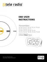
DC-Kit DSP-T 24 – FreshJet, FreshLight, FreshWell
FreshLight
FreshWell
FreshJet
UD+
GND
D+
l5
l4 l3 l2 l1
GND
100 A
100 A
Ubatt
DSP-RCT
R-
E
D
ECL-103
C
B
A
F
F
Batt.1
Batt.2
35 mm
2
35 mm
2
1 mm
2
DSP1824T
230 Vw
t 16 mm
2
t 16 mm
2
t 25 mm
2
D+
+24 V
3
DC-Kit-PP12-DSP-T--IO-16s.book Seite 5 Freitag, 29. Juni 2018 7:17 19

DC-Kit PP12, DSP-T12/24
8
FreshLight
A
B
C
7
DC-Kit-PP12-DSP-T--IO-16s.book Seite 8 Freitag, 29. Juni 2018 7:17 19

EN
DC-Kit PP12, DSP-T12/24
10
Please read this instruction manual carefully before installation and first
use, and store it in a safe place. If you pass on the product to another
person, hand over this instruction manual along with it.
Table of contents
1 Description of symbols . . . . . . . . . . . . . . . . . . . . . . . . . . . . . . . . . . . . . . . 11
2 General safety instructions. . . . . . . . . . . . . . . . . . . . . . . . . . . . . . . . . . . . 11
2.1 General safety . . . . . . . . . . . . . . . . . . . . . . . . . . . . . . . . . . . . . . . . . . .12
2.2 Safety when installing and repairing. . . . . . . . . . . . . . . . . . . . . . . . . .12
2.3 Safe operation . . . . . . . . . . . . . . . . . . . . . . . . . . . . . . . . . . . . . . . . . . .12
3 Scope of delivery. . . . . . . . . . . . . . . . . . . . . . . . . . . . . . . . . . . . . . . . . . . . .13
3.1 DC-Kit PP12 . . . . . . . . . . . . . . . . . . . . . . . . . . . . . . . . . . . . . . . . . . . . .13
3.2 DC-Kit DSP-T12 . . . . . . . . . . . . . . . . . . . . . . . . . . . . . . . . . . . . . . . . . .14
3.3 DC-Kit DSP-T24. . . . . . . . . . . . . . . . . . . . . . . . . . . . . . . . . . . . . . . . . .14
4 Target group for this instruction manual. . . . . . . . . . . . . . . . . . . . . . . .15
5 Intended use. . . . . . . . . . . . . . . . . . . . . . . . . . . . . . . . . . . . . . . . . . . . . . . . .15
6 Technical description . . . . . . . . . . . . . . . . . . . . . . . . . . . . . . . . . . . . . . . . .15
6.1 How the DC kit functions . . . . . . . . . . . . . . . . . . . . . . . . . . . . . . . . . .16
6.2 DC-Kit PP12 . . . . . . . . . . . . . . . . . . . . . . . . . . . . . . . . . . . . . . . . . . . . .18
6.3 DC-Kit DSP-T12 . . . . . . . . . . . . . . . . . . . . . . . . . . . . . . . . . . . . . . . . . .18
6.4 DC-Kit DSP-T24. . . . . . . . . . . . . . . . . . . . . . . . . . . . . . . . . . . . . . . . . .18
7 Installing and connecting the DC kit. . . . . . . . . . . . . . . . . . . . . . . . . . . .19
7.1 Preparing the installation. . . . . . . . . . . . . . . . . . . . . . . . . . . . . . . . . . .19
7.2 Installing components. . . . . . . . . . . . . . . . . . . . . . . . . . . . . . . . . . . . .19
7.3 Connecting air conditioning unit FJ1100, FJ1700, FJ2200, FJ2700,
FJ3200 . . . . . . . . . . . . . . . . . . . . . . . . . . . . . . . . . . . . . . . . . . . . . . . . 20
7.4 Connecting air conditioning unit FL1600, FL2200. . . . . . . . . . . . . .21
7.5 Connecting air conditioning unit FW3000 . . . . . . . . . . . . . . . . . . . .21
7.6 Connecting the DC kit to the power supply . . . . . . . . . . . . . . . . . . 22
7.7 Adjusting the charging current distributor (only DC-Kit PP12/DC-Kit
DSP-T24) . . . . . . . . . . . . . . . . . . . . . . . . . . . . . . . . . . . . . . . . . . . . . . 23
8 Using the DC kit . . . . . . . . . . . . . . . . . . . . . . . . . . . . . . . . . . . . . . . . . . . . . 23
8.1 Switching on the system . . . . . . . . . . . . . . . . . . . . . . . . . . . . . . . . . . 23
8.2 Switching the system off . . . . . . . . . . . . . . . . . . . . . . . . . . . . . . . . . . 24
9 Maintaining and cleaning the DC kit . . . . . . . . . . . . . . . . . . . . . . . . . . 24
DC-Kit-PP12-DSP-T--IO-16s.book Seite 10 Freitag, 29. Juni 2018 7:17 19

EN
DC-Kit PP12, DSP-T12/24 Description of symbols
11
10 Troubleshooting . . . . . . . . . . . . . . . . . . . . . . . . . . . . . . . . . . . . . . . . . . . . 25
11 Warranty . . . . . . . . . . . . . . . . . . . . . . . . . . . . . . . . . . . . . . . . . . . . . . . . . . . 25
12 Disposal . . . . . . . . . . . . . . . . . . . . . . . . . . . . . . . . . . . . . . . . . . . . . . . . . . . . 25
13 Technical data . . . . . . . . . . . . . . . . . . . . . . . . . . . . . . . . . . . . . . . . . . . . . . 26
1 Description of symbols
D
!
A
I
2 General safety instructions
The manufacturer accepts no liability for damage in the following cases:
• Faulty assembly or connection
• Damage to the product resulting from mechanical influences and incorrect
connection voltage
• Alterations to the product without express permission from the manufacturer
• Use for purposes other than those described in the operating manual
DANGER!
Safety instruction: Failure to observe this instruction will cause fatal or
serious injury.
WARNING!
Safety instruction: Failure to observe this instruction can cause fatal or
serious injury.
NOTICE!
Failure to observe this instruction can cause material damage and impair
the function of the product.
NOTE
Supplementary information for operating the product.
DC-Kit-PP12-DSP-T--IO-16s.book Seite 11 Freitag, 29. Juni 2018 7:17 19

EN
General safety instructions DC-Kit PP12, DSP-T12/24
12
2.1 General safety
!
WARNING!
• Observe the safety instructions in the installation and operating man-
ual for the components supplied and your Dometic air conditioner.
• Only use the device as intended.
• People whose physical sensory or mental capacities prevent them
from using this device safely should not operate it without the supervi-
sion of a responsible adult.
• Electrical devices are not toys!
Always keep and use the device out of the reach of children.
• Children must be supervised to ensure that they do not play with the
device.
• Maintenance and repair work may only be carried out by specialist
companies who are familiar with the risks involved and the relevant
regulations.
2.2 Safety when installing and repairing
!
WARNING!
• Installing and repairing the device may only be performed by special-
ist companies that are familiar with the risks as well as the guidelines
and safety precautions to be applied.
2.3 Safe operation
!
• Only operate the system if you are certain that none of the housings
and cables are damaged.
• The DC power connection cables are designed for high levels of
current. Do not make any changes to the cables. If necessary, get a
specialist company to do this for you.
• Make sure the air inlets and outlets of the device are not covered.
WARNING!
Note the following basic safety information when using electrical
devices to protect against:
•Electric shock
•Fire hazards
•Injury
DC-Kit-PP12-DSP-T--IO-16s.book Seite 12 Freitag, 29. Juni 2018 7:17 19

EN
DC-Kit PP12, DSP-T12/24 Scope of delivery
13
• Ensure good ventilation. The inverter produces dissipated heat which
has to be diverted.
• Always disconnect the power supply when working on the device.
3Scope of delivery
Before starting up the system, check that all the parts belonging to the scope of
delivery are present.
3.1 DC-Kit PP12
Quantity Description Ref. number
1 Charging current distributor ECL-76 9600000483
1 Inverter with priority circuit PP1002 9600000022
1 Connection cable
Black power supply line (35 mm², 1.5 m long)
Red power supply line (35 mm², 1.5 m long)
9600000270
1 Sensing cable for FreshJet/FreshLight 4441300221
1 Inverter adapter 9103530084
1 Remote control for inverter MCR9 9600000091
1 Installation and operating manual 4445101952
DC-Kit-PP12-DSP-T--IO-16s.book Seite 13 Freitag, 29. Juni 2018 7:17 19

EN
Scope of delivery DC-Kit PP12, DSP-T12/24
14
3.2 DC-Kit DSP-T12
3.3 DC-Kit DSP-T24
Quantity Description Ref. number
1 Charging current distributor ECL-102 9600000547
1 Inverter DSP1812T with priority circuit 9600002553
1 Remote control for inverter DSP-RCT
(including connection cable)
9600002564
1 Connection cable
Black power supply line (35 mm², 1.5 m long)
Red power supply line (35 mm², 1.5 m long)
4441300120
4441300119
1 Adapter cable for FreshJet/FreshLight/FreshWell 4441300221
1 Extension cable 4441300124
1 Installation and operating manual 4445101954
Quantity Description Ref. number
1 Charging current distributor ECL-103 9600000548
1 Inverter DSP1824T with priority circuit 9600002554
1 Remote control for inverter DSP-RCT
(including connection cable)
9600002564
1 Connection cable
Black power supply line (35 mm², 1.5 m long)
Red power supply line (35 mm², 1.5 m long)
4441300120
4441300119
1 Adapter cable for FreshJet/FreshLight/FreshWell 4441300221
1 Extension cable 4441300124
1 Installation and operating manual 4445101956
DC-Kit-PP12-DSP-T--IO-16s.book Seite 14 Freitag, 29. Juni 2018 7:17 19

EN
DC-Kit PP12, DSP-T12/24 Target group for this instruction manual
15
4 Target group for this instruction manual
The installation information in this instruction manual is intended for specialist
companies that are familiar with the guidelines and safety precautions to be applied
during the installation of vehicle accessory parts.
All other chapters are intended for the users.
5 Intended use
The “DC kit” extension kit is suitable for equipping the following Dometic air
conditioning units for DC power drive operation:
• DC-Kit PP12 (ref. no. 9100300003), 12 Vg
– FJ1100
• DC-Kit DSP-T12 (ref. no. 9100300002), 12 Vg
– FJ1100, FJ1700, FJ2200, FJ2700, FJ3200
– FL1600, FL2200
–FW3000
• DC-Kit DSP-T24 (ref. no. 9100300073), 24 Vg
– FJ1100, FJ1700, FJ2200, FJ2700, FJ3200
– FL1600, FL2200
–FW3000
If the air conditioning unit does not have a heat pump (see instruction manual for air
conditioning unit), the inverter may only be used for cooling by the air conditioning
unit, not for heating mode, as the heating elements consume more current than the
inverter can generate in continuous operation.
6 Technical description
The extension kit consists of the following components:
• The charging current distributor with low-voltage cut-off regulates the current
distribution between the starter battery, supply battery and light system, as well
as the operation of the air conditioning unit. It prevents the battery and the elec-
tronics in the vehicle from overloading.
• The inverter supplies the air conditioning unit with the necessary input voltage of
230 Vw. The inverter generates this 230 V input voltage from the DC on-board
supply in the vehicle.
DC-Kit-PP12-DSP-T--IO-16s.book Seite 15 Freitag, 29. Juni 2018 7:17 19

EN
Technical description DC-Kit PP12, DSP-T12/24
16
The built-in priority circuit is intended for distributing voltages in vehicles with
two available current supplies. If there is mains voltage present at the device, this
is prioritized. This ensures that the limited power of the battery is not used
unnecessarily. If there is no mains voltage present, the DC on-board supply is
used.
• The remote control can be used to switch the inverter on and off.
The charging current distributor has two relays that are used as follows:
• Power relay (Batt. 1/Batt. 2)
to connect the starter and consumer battery
• Control relay
to switch the compressor on and off
–ECL-76: fig.1, page 3
– ECL-102: fig. 2, page 4
– ECL-103: fig. 3, page 5
Key for circuit diagrams in fig. 1, page 3 to fig. 3, page 5
6.1 How the DC kit functions
The DC kit measures the light system voltage UD+ and compares this value against
the value of the switch-on voltage Ue.
The voltage value Ue can be adjusted for ECL-76 and ECL-102 (12.5 V – 14.0 V). For
ECL-103, the voltage value Ue is 26.6 V.
Characters in
circuit diagram
Explanation
A Starter battery
B Consumer unit battery
C Remote control
D Ua: switch-off voltage
E Ue: switch-on voltage
FFuse
DC-Kit-PP12-DSP-T--IO-16s.book Seite 16 Freitag, 29. Juni 2018 7:17 19

EN
DC-Kit PP12, DSP-T12/24 Technical description
17
Supply from the battery with motor switched on
If the light system voltage exceeds the voltage value Ue (UD+ > Ue), relay contact
Batt. 1/Batt. 2 of the power relay closes. The starter battery and the consumer
battery are therefore connected in parallel with low resistance and are charged
together by the light system. In addition, the contact I2/I4 opens. This activates the
air conditioning unit.
If the light system voltage falls below the switch-off value Ua for the charging current
distributor due to the high load from the air conditioning unit, relay contact Batt. 1/
Batt. 2 opens and the parallel connection between the starter battery and the con-
sumer battery ends. The light system now charges the starter battery. If the vehicle
has a connecting cable between the two batteries, the consumer battery is also
charged.
In addition, the contact I2/I4 closes. This switches off the compressor of the air
conditioning unit. The air conditioning unit fan and the inverter remain in operation.
The lower limit value Ua can be adjusted for ECL-76 and ECL-102 (10.5 V – 12.5 V).
For ECL-103, the voltage value Ua is 23.4 V.
As soon as the voltage in the consumer battery has reached the switch-on value Ue
for the charging current distributor, the compressor of the air conditioning unit
switches on again.
If the voltage in the consumer battery drops further and falls below the switch-off
point for the inverter, the inverter switches off.
Supply from the battery with motor switched off
If the vehicle engine is switched off (UD+ = 0 V), relay contact Batt. 1/Batt. 2 and
relay contact I2/I4 are open. The air conditioning unit can be operated and only
takes power from the consumer battery. If the battery voltage falls below
Ubatt = 10.5 V/21 V, the inverter switches off. There is no longer any voltage at
the corresponding socket and the air conditioning unit switches off.
As soon as the power from the consumer battery reaches the inverter's switch-on
point, the socket is supplied with voltage again. The air conditioning unit has to be
switched back on manually.
DC-Kit-PP12-DSP-T--IO-16s.book Seite 17 Freitag, 29. Juni 2018 7:17 19

EN
Technical description DC-Kit PP12, DSP-T12/24
18
6.2 DC-Kit PP12
• Air conditioner: FreshJet1100
• Circuit diagram: fig. 1, page 3
• Charging current distributor: ECL-76
• Inverter: PerfectPower PP1002
6.3 DC-Kit DSP-T12
• Air conditioning units:
– FreshJet1100/1700/2200/2700/3200
– FreshLight1600/2200
– FreshWell3000
• Circuit diagram: fig. 2 , page 4
• Charging current distributor: ECL-102
• Inverter: SinePower DSP1812T
6.4 DC-Kit DSP-T24
• Air conditioning units:
– FreshJet1100/1700/2200/2700/3200
– FreshLight1600/2200
– FreshWell3000
• Circuit diagram: fig. 3 , page 5
• Charging current distributor: ECL-103
• Inverter: SinePower DSP1824T
DC-Kit-PP12-DSP-T--IO-16s.book Seite 18 Freitag, 29. Juni 2018 7:17 19

EN
DC-Kit PP12, DSP-T12/24 Installing and connecting the DC kit
19
7 Installing and connecting the DC kit
!
A
Observe the following instructions when selecting the location for installing the
components:
• Make sure the cables are of the correct length.
• Choose a well-ventilated installation location near the supply battery.
7.1 Preparing the installation
➤ Disconnect the following voltage supplies in the vehicle:
– negative battery terminal
– external voltage supply
7.2 Installing components
➤ Install the charging current distributor.
Attach the charging current distributor and the corresponding relay so that they
are installed firmly, are dry and well ventilated, ideally in the direct vicinity of the
inverter.
➤ Install the inverter.
WARNING!
• The DC kit may only be installed by specialist companies.
• To prevent the risk of short circuits, always disconnect the negative
terminal of the vehicle’s electrical system before working on the vehi-
cle’s electrical system.
If the vehicle has a consumer battery, its negative terminal should
also be disconnected.
• The minimum cable cross sections are shown in the following dia-
grams:
–ECL-76: fig.1, page 3
–ECL-102: fig.2, page 4
–ECL-103: fig.3, page 5
NOTICE!
• Make sure that you route the on/off cable away from live power
cables.
• When installing, observe the information in the installation and
operating manual for the components supplied and your Dometic air
conditioner.
DC-Kit-PP12-DSP-T--IO-16s.book Seite 19 Freitag, 29. Juni 2018 7:17 19

EN
Installing and connecting the DC kit DC-Kit PP12, DSP-T12/24
20
➤ Install the remote control.
D
7.3 Connecting air conditioning unit FJ1100, FJ1700,
FJ2200, FJ2700, FJ3200
➤ Remove the air outlet unit of the air conditioner; if necessary remove the top
cover ( FreshJet) (fig. 5, page 6).
➤ Connect the on/off cable for the FreshJet to the connection socket on the circuit
board (fig. 6, page 7).
I
PP12
Circuit diagram: fig. 1, page 3
➤ Route the on/off cable from the air conditioning unit to the charging current
distributor.
➤ Connect the on/off cable to connections I4 and I2 on the charging current
distributor (fig. 4, page 6).
➤ Connect the inverter adapter ( Inverter Adapter).
➤ Attach the air outlet unit of the air conditioner ( FreshJet) (fig. 5, page 6).
➤ Route the connecting cable for remote control MCR9 to the inverter and connect
it ( inverter).
DSP-T12/24
Circuit diagram:
• DC-Kit DSP-T12: fig. 2, page 4
• DC-Kit DSP-T24: fig. 3, page 5
➤ Connect the adapter cable to the on/off cable.
➤ Connect the extension cable to the adapter cable.
➤ Connect the extension cable to connections I2 and I5 on the charging current
distributor (fig. 4, page 6).
DANGER! Electric shock!
Only connect the battery once you have the completed all the installa-
tion work and you are certain it has been done properly.
NOTE
Guide the on/off cable carefully past the fan.
DC-Kit-PP12-DSP-T--IO-16s.book Seite 20 Freitag, 29. Juni 2018 7:17 19

EN
DC-Kit PP12, DSP-T12/24 Installing and connecting the DC kit
21
➤ Attach the air outlet unit of the air conditioner (fig. 5, page 6).
➤ Route the connecting cable for remote control DSP-RCT to the inverter and con-
nect it ( inverter).
7.4 Connecting air conditioning unit FL1600, FL2200
➤ Remove the air outlet unit of the air conditioner; if necessary remove the top
cover ( FL1600, FL2200) (fig. 7, page 8).
➤ Connect the on/off cable for the FreshLight to the connection socket on the
circuit board (fig. 8, page 9).
I
➤ Connect the adapter cable to the on/off cable.
➤ Connect the extension cable to the adapter cable.
➤ Connect the extension cable to connections I2 and I5 on the charging current
distributor (fig. 4, page 6).
➤ Attach the air outlet unit of the air conditioner ( FreshLight) (fig. 7, page 8).
➤ Route the connecting cable for remote control DSP-RCT to the inverter and
connect it ( inverter).
7.5 Connecting air conditioning unit FW3000
➤ Connect the on/off cable for FW3000 to the connection socket on the
connector panel (fig. 9, page 9).
I
➤ Connect the adapter cable to the on/off cable.
➤ Connect the extension cable to the adapter cable.
➤ Connect the extension cable to connections I2 and I5 on the charging current
distributor (fig. 4, page 6).
➤ Route the connecting cable for remote control DSP-RCT to the inverter and
connect it ( inverter).
NOTE
Guide the on/off cable carefully past the fan.
NOTE
Guide the on/off cable carefully past the fan.
DC-Kit-PP12-DSP-T--IO-16s.book Seite 21 Freitag, 29. Juni 2018 7:17 19

EN
Installing and connecting the DC kit DC-Kit PP12, DSP-T12/24
22
7.6 Connecting the DC kit to the power supply
Circuit diagram:
•DC-Kit PP12: fig.1, page 3
• DC-Kit DSP-T12: fig. 2, page 4
• DC-Kit DSP-T24: fig. 3, page 5
➤ Check that all the connections have been made in accordance with the
instructions.
➤ Check that the air conditioning unit is properly sealed.
➤ Connect the charging current distributor:
– Connect the positive terminal of the starter battery to relay connection Batt. 1.
– Connect the positive terminal of the consumer battery to relay connection
Batt. 2.
– Insert an electrical fuse (see corresponding circuit diagram for the value) in
direct proximity to the starter battery and an electrical fuse in direct proximity
to the supply battery into the positive cable.
I
➤ Connect the AC connection of the air conditioning unit to the plug of the inverter
( inverter).
➤ Connect the positive battery cables to the batteries.
➤ Check the following are working properly:
– Check the on and off values for the charging voltage regulator
– Check the functioning of the priority circuit
– Switch on the air conditioning in driving mode ( air conditioning unit)
– Switch on the air conditioning in mains supply mode ( air conditioning unit)
NOTE
• The fuse in the positive cable from the charging current distributor to
the battery can only be omitted if the lead is very short and will not
come into contact with metal.
• To connect the inverter included in the scope of delivery of the
DC kit, please refer to the instruction manual for the device.
DC-Kit-PP12-DSP-T--IO-16s.book Seite 22 Freitag, 29. Juni 2018 7:17 19

EN
DC-Kit PP12, DSP-T12/24 Using the DC kit
23
7.7 Adjusting the charging current distributor
(only DC-Kit PP12/DC-Kit DSP-T24)
A
I
➤ Insert a screwdriver into the axis of the potentiometer (fig. 0, page 9).
Turning the axis clockwise increases the voltage threshold value, turning it
counter-clockwise reduces the voltage threshold value.
I
8 Using the DC kit
This chapter contains information on operating the overall system. This operating
manual does not replace any information contained in the installation and operating
instructions for the individual components.
I
8.1 Switching on the system
Observe the following instructions before you switch on the system:
• Air the vehicle.
• Make sure that the ventilation slots on the air nozzles and the fan of the compo-
nents are not covered up.
NOTICE!
The following work must be carried out with caution and only by persons
with the necessary skills and knowledge. This is because incorrect
adjustment of the switch-on and switch-off voltages can cause the air
conditioner to malfunction and may cause the vehicle’s electrical system
to fail.
NOTE
The voltage scale shown on the charging current distributors is a guide.
If different values are set, these must be checked using a suitable voltage
measurement device. An externally adjustable laboratory power supply
can be connected to terminals GND and D+ for this purpose.
NOTE
We recommend against setting a switch-off voltage below 11.5 V.
NOTE
Only DC-Kit 12PP: The operating noises made by the air conditioning
unit are louder during mobile air conditioning than during stationary air
conditioning. The noises are caused by using the inverter.
DC-Kit-PP12-DSP-T--IO-16s.book Seite 23 Freitag, 29. Juni 2018 7:17 19

EN
Maintaining and cleaning the DC kit DC-Kit PP12, DSP-T12/24
24
• Make sure that none of the housings and cables are not damaged and that all the
insulation is intact.
• Compare the existing supply voltage against the technical data.
• Do not insert any fingers or objects into component openings.
Stationary mode: AC mains supply mode
The system is supplied from the AC mains.
Driving mode: power supply from the battery
I
➤ Switch on the inverter using the remote control.
➤ Use the air conditioning unit as described in the operating manual.
8.2 Switching the system off
➤ First of all, switch off the air conditioning unit.
➤ If there are no more consumer units that need power, switch off the inverter using
the remote control.
9 Maintaining and cleaning the DC kit
A
I
➤ Clean the charging current distributor with a damp cloth from time to time.
➤ Check the power supply lines for abrasion or defects regularly.
➤ Have the system checked regularly by a specialist company.
➤ If you find any faulty fuses, have the system checked by a specialist company.
NOTE
See also: chapter “How the DC kit functions” on page 16.
NOTICE!
Do not use sharp or hard objects or cleaning agents for cleaning as these
may damage the product.
NOTE
Observe the maintenance and cleaning instructions in the operating
manuals of the individual components.
DC-Kit-PP12-DSP-T--IO-16s.book Seite 24 Freitag, 29. Juni 2018 7:17 19

EN
DC-Kit PP12, DSP-T12/24 Troubleshooting
25
10 Troubleshooting
I
11 Warranty
The statutory warranty period applies. If the product is defective, please contact the
manufacturer's branch in your country (see the back of the instruction manual for the
addresses) or your retailer.
For repair and warranty processing, please include the following documents when
you send in the device:
• A copy of the receipt with purchasing date
• A reason for the claim or description of the fault
12 Disposal
➤ Place the packaging material in the appropriate recycling waste bins wherever
possible.
M
If you wish to finally dispose of the product, ask your local recycling centre
or specialist dealer for details about how to do this in accordance with the
applicable disposal regulations.
NOTE
Observe the instructions on rectifying faults in the operating manuals of
the individual components.
DC-Kit-PP12-DSP-T--IO-16s.book Seite 25 Freitag, 29. Juni 2018 7:17 19
/