Page is loading ...

Instruction
Manual
Torque Measuring
Flange
Type 4510B…
Compatible with
Firmware-Version
Stator: >V2.06
Rotor: >V1.9
ä
4510B_002-543e-01.14

Instruction
Manual
Torque Measuring
Flange
Type 4510B…
Compatible with
Firmware-Version
Stator: >V2.06
Rotor: >V1.9
ä
4510B_002-543e-01.14


Foreword
4510B_002-543e-01.14 Page 1
Foreword
This manual applies to the torque measuring flange Type
4510B… .
The instruction manual must be kept on hand for future
use, and must be available at the site of implementation of
the Torque measuring flange, as needed.
The specifications in this manual can change at any time
without prior notification. Kistler reserves the right to
improve and to change the product for the purpose of
technical progress without the obligation to inform persons
and organizations as the result of such changes.
Original language of these operating instructions: German
©2009 … 2014 Kistler Group. All rights reserved.
Kistler Group
Eulachstrasse 22
8408 Winterthur
Switzerland
phone +41 52 224 11 11
fax +41 52 224 14 14
info@kistler.com
www.kistler.com
Product Center
Torque measuring flanges, NC Joining Systems,
Force-Displacement Monitoring, Test Stand Systems
Kistler Lorch GmbH
Maierhofstrasse 35
73547 Lorch
Germany
phone +49 7172 184 0
fax +49 7172 184 400
info.klr@kistler.com

Torque Measuring Flange, Type 4510B…
Page 2 4510B_002-543e-01.14
Content
1. Introduction ................................................................................................................................... 4
2. Important Information .................................................................................................................... 5
2.1 Disposal Instructions for Electrical and Electronic Equipment ................................................ 5
3. Application and Typical Features ................................................................................................... 6
4. Description of the Measuring System ............................................................................................ 7
4.1 Mechanical Design ............................................................................................................... 7
4.2 Electrical Design ................................................................................................................... 7
4.2.1 Speed Measurement with 60 Pulses ........................................................................ 9
5. Electrical Connection of Torque Measuring Flange ...................................................................... 10
5.1 Supply ................................................................................................................................ 10
5.1.1 Power Consumption of the Torque Measuring Flange with Different Supply
Voltages ................................................................................................................ 10
5.2 Principle of Galvanic Isolation in the Torque Measuring Flange .......................................... 11
5.3 Plug Allocation of the 12 pin Built-in Standard Connector A .............................................. 12
5.4 Plug Allocation of the 7 pin Built-in Standard Connector B ................................................. 12
5.4.1 Measuring Range Selection ................................................................................... 13
5.4.2 Digital Output, Measuring Value via RS-232C Interface ........................................ 13
5.4.3 Connection Diagram Standard Sensor ................................................................... 14
5.4.4 Pin Allocation of the Built-In Connector A and B (standard) .................................. 15
6. Connection Cable ......................................................................................................................... 16
6.1 Laying of the Measuring Cable........................................................................................... 17
6.2 Advice for Safe Electrical Installation................................................................................... 18
7. Mechanical Installation of the Torque Measuring Flange ............................................................ 19
7.1 Installation Proposals .......................................................................................................... 20
7.1.1 Shaft Tolerance ..................................................................................................... 20
7.1.2 Aligning Stator to Rotor ......................................................................................... 20
7.1.3 Installation and Removal Instructions for Shrinking Disks ...................................... 21
7.2 Suggestion for Installation .................................................................................................. 23
7.2.1 Connection of Rotor, Fastening Bolts .................................................................... 23
8. Electrical and Mechanical Commissioning ................................................................................... 24
8.1 Operating LED ................................................................................................................... 24
8.2 Adjusting and Calibrating the Torque measuring flange ..................................................... 25
8.3 Mechanical Calibration ....................................................................................................... 26
8.3.1 Set-up of a Simple Calibration Device .................................................................... 26
8.3.2 Calculation Example, Lever Arm Length ................................................................ 27
9. Making Torque Measurements .................................................................................................... 28
9.1 Switch on the Torque measuring flange ............................................................................. 28
9.2 Qualities After Switching Measuring Range ....................................................................... 28

Content
4510B_002-543e-01.14 Page 3
10. RS-232C Communication ............................................................................................................. 29
10.1 Interface Parameters ........................................................................................................... 30
10.1.1 Conventions and Syntax ........................................................................................ 30
10.1.2 Error Messages ....................................................................................................... 32
10.1.3 Measuring Rates, Reaction Times ........................................................................... 33
10.1.4 Requesting Torque Values Through RS-232C Command ....................................... 34
10.1.5 Requesting Torque Measuring Values via External Triggering ................................ 35
10.2 Typical Measuring Sequence ............................................................................................... 36
10.3 Configuration Commands ................................................................................................... 37
10.3.1 Range Selection...................................................................................................... 37
10.3.2 Control Signal (Calibration Signal) On or Off ......................................................... 38
10.3.3 Value Query – Configuration for the MEAS Command .......................................... 39
10.3.4 Defining the Output Format .................................................................................. 40
10.3.5 Determining the Trigger Mode ............................................................................... 41
10.3.6 Determining Sensor Data ....................................................................................... 42
10.4 Measuring Commands ........................................................................................................ 45
10.4.1 Transmitting Torque and Temperature Measuring Quantity .................................. 45
11. Maintenance ................................................................................................................................. 47
12. Repairing the Measuring Shaft ..................................................................................................... 47
13. Technical Data .............................................................................................................................. 48
13.1 Mechanical Basic Data ........................................................................................................ 48
13.2 General Electrical Specifications ........................................................................................... 48
13.3 Electrical Measuring Data – Standard Measuring Range 1:1 ................................................ 49
13.4 Electrical Measuring Data – Extended Measuring Range 1:5, 1:10 ...................................... 49
14. Dimensions ................................................................................................................................... 50
15. Ordering Key and Accessories ...................................................................................................... 52
16. Declaration of Conformity ............................................................................................................ 53
17. Index ............................................................................................................................................. 54
Total Pages 54

Torque Measuring Flange, Type 4510B…
Page 4 4510B_002-543e-01.14
1. Introduction
Please take the time to thoroughly read this instruction
manual. It will help you with the installation, maintenance,
and use of this product.
To the extent permitted by law Kistler does not accept any
liability if this instruction manual is not followed or
products other than those listed under Accessories are
used.
Kistler offers a wide range of products for use in measuring
technology:
Piezoelectric sensors for measuring force, torque, strain,
pressure, acceleration, shock, vibration and acoustic-
emission
Strain gage sensor systems for measuring force and
torque
Piezoresistive pressure sensors and transmitters
Signal conditioners, indicators and calibrators
Electronic control and monitoring systems as well as
software for specific measurement applications
Data transmission modules (telemetry)
Electromechanical NC joining modules and force-
displacement monitors
Test stand systems for electric motors and gear units for
laboratory, manufacturing, and quality assurance
Kistler also develops and produces measuring solutions for
the application fields engines, vehicles, manufacturing,
plastics and biomechanics sectors.
Our product and application brochures will provide you
with an overview of our product range. Detailed data
sheets are available for almost all products.
If you need additional help beyond what can be found
either on-line or in this manual, please contact Kistler's
extensive support organization.

Important Information
4510B_002-543e-01.14 Page 5
2. Important Information
2.1 Disposal Instructions for Electrical and Electronic Equipment
Do not discard old electronic instruments in municipal
trash. For disposal at end of life, please return this
product to an authorized local electronic waste disposal
service or contact the nearest Kistler Instrument sales
office for return instructions.

Torque Measuring Flange, Type 4510B…
Page 6 4510B_002-543e-01.14
11 ... 30 VDC
11 ... 30 VDC 0 ... ±10 V
0 V
Elektronic
Stator
Support
Torque
Speed
3. Application and Typical Features
Torque measuring flange with strain gage measuring
system
Digitalized wear-resistant measuring signal transmission
Measurement of constant and variable torques
Torque measurement on the rotating shaft
Application in the laboratory, production and quality
control
Torque measuring flange for precision measurements
With speed measurement
2-color LED for operating condition
Galvanic isolation between supply and torque output
signal
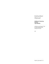
Fig. 1: Standard version of a torque measuring flange
Type 4510B...

Description of the Measuring System
4510B_002-543e-01.14 Page 7
4. Description of the Measuring System
4.1 Mechanical Design
The torque measuring flange consisting of a stator with
support and a rotating rotor.
On the measuring flange at the torsion section strain gages
are arranged, as well as electronics with signal amplifier
and A/D converter. In the connection box of the stator the
stationary electronics for signal shaping are positioned. The
stator provides various assembly possibilities.
4.2 Electrical Design
The following schematic diagram represents the principle
of operation of a digital value transmission.
Feed of the electronics is performed by a DC voltage in the
range of 11 … 30 V (±25 %). Free programmable controls
(PLC) provide a DC voltage of 24 V, which may of course
be utilized for feeding the torque measuring flange.
A crystal controlled power oscillator creates the system
cycle and feeds the rotating electronics through concentric
rotary transmitters.
In the rotating electronics this alternating voltage is
rectified and stabilized. The measuring signal of the strain
gage is increased and digitalized through a rapid serial A/D
converter. The modulation with 1 MHz allows a back
transfer through air-core coils.

Torque Measuring Flange, Type 4510B…
Page 8 4510B_002-543e-01.14
Fig. 2: Schematic block diagram of Torque measuring
flange Type 4510B...
In the outside electronics the digitalized strain gage signal
is reconverted into an analog signal of ±10 Volt during the
transmission.
Optionally a frequency-based signal can be produced. In
addition there is the option of transmitting the torque-
measuring signal through the RS-232C interface.
Through an extern digital control signal a defined strain
gage signal value can be activated on the shaft, which
corresponds to the rated torque.
With an external digital measurement range signal the
amplification of the strain gage amplifier can be switched.
Output
±10 V
Stabilization
Oscillator
(1 MHz)
Modulator
Micro
computer
AC/DC
Rotary
transmitter
Pulse shaper
D/A-
converter
Control
Rotary
transmitter
Strain gage
A/D +
Modulation
Torque Measuring Flange
Gain
1:1 or 1:10
Measurement
range switch
3,5 ... 30 VDC
RS-232C
Supply
11 ... 30 VDC
Control signal
3,5 ... 30 VDC

Description of the Measuring System
4510B_002-543e-01.14 Page 9
4.2.1 Speed Measurement with 60 Pulses
The measuring of the speed of rotation is integrated in this
torque measuring flange. This is realized by a pulse wheel
with 60 pulses.
A pulse wheel with 60 pulses. Raised sections on the
wheel are detected with the aid of a magnetic sensor.
This speed measurement system is provided as a
standard feature
Fig. 3:
Electrical circuit diagram of speed measurement
with pulse wheel
Pulse wheel with 60 pulses
Probe
Driver
Connector A (12 pin)
Connector C
External
counter
External
counter
Measuring Flange
U
0 V
B
H
E
1
8/6
20 mA
Connector B (7 pin)
External
counter
Probe
Driver
Torque Measuring Flange
Wheel with 60 pulses

Torque Measuring Flange, Type 4510B…
Page 10 4510B_002-543e-01.14
5. Electrical Connection of Torque Measuring Flange
5.1 Supply
To supply torque measuring flange Type 4510B…, a
supply voltage in the range of:
11 ... 30 VDC Direct Voltage
is necessary.The direct voltage is supplied to the integrated
12 pin connector on pin F (+UB) and A (GND) . The power
consumption is approx. 2,5 W. The supply and torque
output are electrically isolated in the torque measuring
flange.
5.1.1 Power Consumption of the Torque Measuring Flange with Different Supply
Voltages
Fig. 4: Input current as a function of the input voltage
90
110
130
150
170
190
210
230
11 12 13 14 15 16 17 18 19 20 21 22 23 24 25 26 27 28 29 30
Betriebsspannung in V
Strom in mA
Current in mA
Operational voltage in V

Electrical Connection of Torque Measuring Flange
4510B_002-543e-01.14 Page 11
Fig. 5: Possible power supplier devices for Torque
measuring flange
5.2 Principle of Galvanic Isolation in the Torque Measuring Flange
Fig. 6: Block diagram of galvanic isolation in the
Torque measuring flange
L1
PE
N
F
A
M
Torque
measuring flange
+U
B
Screen
(housing)
GND
12 pin connector
CoMo Torque Type 4700B…
/VA 3600 Type 4704A…
or
stabilized
power supply
11 … 30 VDC/min. 1A
Screen
ground
Ground for range selection
and control signal
Ground analog-/
Frequency output
Ground other input/
outputs
Internal voltages
DC
DC
Torque Measuring Flange
Screen
(housing)
A
F
D
E
+UB
GND
AGND
DGND
Supply
DGND
PIN 3
Ground for RS-232C
OGND
O
D
O
PIN 1
PIN 4
PIN 7
Range selection
Control signal

Torque Measuring Flange, Type 4510B…
Page 12 4510B_002-543e-01.14
5.3 Plug Allocation of the 12 pin Built-in Standard Connector A
5.4 Plug Allocation of the 7 pin Built-in Standard Connector B

Electrical Connection of Torque Measuring Flange
4510B_002-543e-01.14 Page 13
5.4.1 Measuring Range Selection
Must be:
Option A1 (measuring range 1:10) or
Option A2 (measuring range 1:5, technical data
like 1:10)
All specifications are for the measuring range 1:10 and
1:5.
If the torque measuring sensor is additionally calibrated in
the range of 1:10 at the factory, the requested range may
be switched via PIN 1 and PIN 7.
Measuring range logic condition voltage level
1:1 PIN1 = 0 UPIN1,7 = 0 ... 2 V
1:10 PIN1 = 1 UPIN1,7 = 3,5 ... 30 V
For each measuring range the logic condition at PIN 1 must
continue.
Optional the measuring range can be switched via the
RS-232C interface.
5.4.2 Digital Output, Measuring Value via RS-232C Interface
Must be: Option D (RS-232C interface)
With this option torque values can be sent via the
RS-232C interface. Additional notes are in the chapter
"RS-232C communication".

Torque Measuring Flange, Type 4510B…
Page 14 4510B_002-543e-01.14
5.4.3 Connection Diagram Standard Sensor
Fig. 7: Example for connecting standard Torque
measuring flange
Type 4510B... to the supply and evaluation unit
Screened measuring cable: Item no. 7203, Mat. No.:
188935 (item no. 12497, Mat.-no.: 18008943 with
opened ends)
Supply and evaluation unit: e.g.: VA3600, CoMo
Torque Type 4700B…
Built-in connector: Binder series 680 type 09-0331-80-
12 or corresponding, item no. 703.
The displayed connection example disables the galvanic
isolation in the Torque measuring flange, if the control
button is switched on (e.g. PLC relays). Avoid EMC
noises on the measuring cable.
In order to avoid errors, please note if cables are longer
than 10 m and conductors are distributed, that the
speed signal is isolated from the torque signal by
feeders, just as in the connector.
Torque Measuring
Sensor
Type 4510B…
DVM
F
A
C
D
H
E
K
M
Supply 11…30 VDC
Speed/angle output
Control signal input
Control button
5 V TTL (track A)
DGND (0V)
+U
B
Ground U
B
±
10 V
AGND (0 V)
3,5 ... 30 V
Shield
Supply and
evaluation unit
=
~
Counter
G
5 V TTL (track B)
*
Torque output

Electrical Connection of Torque Measuring Flange
4510B_002-543e-01.14 Page 15
5.4.4 Pin Allocation of the Built-In Connector A and B (standard)
Fig. 8: Connection diagram of torque measuring
flange Type 4510B… with one or both options
range selection/RS-232C interface to supply
and evaluation units

Torque Measuring Flange, Type 4510B…
Page 16 4510B_002-543e-01.14
6. Connection Cable
Technical Data
Type KSM072030-5
Mat. No: 18008935
Connector
12 pin neg. – 12 pin pos.
Length
m
5 (other length on request)
Diameter
mm
6
Deg. of protection to IEC/EN 60529
IP40
Technical Data
Type KSM124970-5
Mat. No. 18008943
Connector
12 pin neg. – flying leads
Length
m
5 (other length on request)
Diameter
mm
6
Deg. of protection to IEC/EN 60529
IP40

Connection Cable
4510B_002-543e-01.14 Page 17
Technical Data
Type KSM219710-5
Mat. No. 18008996
Connector
7 pin neg. – flying leads
Length
m
5 (other length on request)
Diameter
mm
6
Deg. of protection to IEC/EN 60529
IP40
6.1 Laying of the Measuring Cable
Do not lay parallel to power lines or control lines
not in the vicinity of heavy electro-magnetic fields, e.g.
transformers, welding devices, contactors, motors etc
If this cannot be avoided, lay the measuring cable in a
grounded armored conduit
Excess lengths should be prevented. If it isn’t possible to
avoid, then do not lay excess lengths in closed loops
Fig. 9: Laying of the measuring cable
Risk to couple in EMC noises into the measuring
sensor cable
To reduce the inductive areas it’s recommended to
laying the measuring sensor cable in bifilar form
Measuring cable Cable tunnel
Measuring cable Cable tunnel
!
/