Page is loading ...

TJ BODY ARMOR KIT
Installation Instructions
Full (6pcs) kit and sub kits
The following instructions are supplied to help aid with the
installation part number 11650.50 and can be used with all sub
kits. It is the responsibility of the purchaser to properly install all
components as described in supplied instructions. OMIX ADA is
not responsible for products once attached to vehicles.

11650.17 (Hood Stone Guard)
Installation Instructions
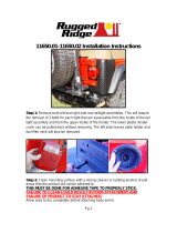
Step 1: Clean mounting surface with a strong cleaner or rubbing alcohol. Avoid
areas that the product will not be adhered to.
THIS MUST BE DONE FOR ADHESIVE TAPE TO PROPERLY STICK.
FAILURE TO CLEAN COULD RESULT IN POOR ATTACHMENT AND
FAILURE OF PRODUCT TO STAY ATTACHED.
Allow area to dry completely before attaching body armor.
TOOLS NEEDED: (1) Drill, (1) 7/64” drill bit, and (1) Phillips Head screw driver.
Step 2: Test fit the Hood Guard to the vehicle before removing the plastic
backing film. This will aid in aligning the piece properly before securing with the
two-sided 3M tape.
Step 3: Remove plastic backing film from the affixed two-sided 3M tape. The
plastic film can be removed easier with the aid of a knife or cutting blade. Peel
from leading edges and pull away from tape.

Step 4: Position Hood Armor close to the hood and attach from the center of
hood outward to the edges. Make sure that it is evenly spaced before applying
any pressure to armor. When satisfied with placement apply pressure to all areas
to properly secure armor to vehicle.
Step 5: After installation, inspect to make sure all tape areas are adhered
securely to the vehicle before driving.
NOTE: it is important that the Hood Armor be positioned as far back onto
the hood as possible. There should be NO GAP between the front of the
hood and the inside of the Hood Armor
Step 6: With Hood Armor in the correct position and firmly attached to the vehicle
mark or scribe two hole locations on each side of the inner hood. These marks
are to be drilled using a 7/64” drill bit. Make sure mark locations are positioned as
far inward as possible. This will allow the screws to be located flush with the
hood and grille line when lowered. With marks in place carefully drill the two
7/64” holes. TAKE CARE NOT TO DRILL TO FAR PAST THE INNER LIP OR
DAMAGE TO OUTER HOOD SURFACE MAY RESULT.

Step 7:After holes have been drilled using the 7/64” bit insert screws to secure
Hood Armor to vehicle using a Phillips head screwdriver.
When properly installed the retaining screws should just be visible inside of the
vehicle hood line and not interfere with the closing or locking of the hood.
OMIX – ADA or Rugged Ridge is not responsible for damage to vehicle or injuries acquired
during the installation or use of this accessory.

Part Number 11650.20(Front Fender guards)
Step 7: Remove the hood stoppers and front turn signals from both front fenders.
Step 8: Clean mounting surface with a strong cleaner or rubbing alcohol. Avoid
areas that the product will not be adhered to.
THIS MUST BE DONE FOR ADHESIVE TAPE TO PROPERLY STICK.
FAILURE TO CLEAN COULD RESULT IN POOR ATTACHMENT AND
FAILURE OF PRODUCT TO STAY ATTACHED.
Allow area to dry completely before attaching body armor.
Step 9: Test fit the Fender Guard to the vehicle before removing the plastic
backing film. This will aid in aligning the piece properly before securing with the
two-sided 3M tape.
Step 10: Remove plastic backing film from the affixed two-sided 3M tape.

Step 11: Position armor onto fender Make sure that it is evenly spaced before
applying any pressure to armor. When satisfied with placement apply pressure
to all areas to properly secure armor to vehicle. Reinstall the front turn signals
with supplied longer screws. Do not over tighten turn signal screws or lens
assembly may crack.
Part Number 11650.01 or 11650.02 (Rear Corner
Guards)
Step 12: Remove both left and right side rear tail light assembles. This will
require the removal of 3 bolts for each light that are assessable from the inside of
the tail light assembly and from the upper inside of the fender. The lower plastic
fender cover can be pulled back without removing. The left side license plate
holder and fuel filler neck will also be removed.

Step 13: Clean mounting surface with a strong cleaner or rubbing alcohol. Avoid
areas that the product will not be adhered to.
THIS MUST BE DONE FOR ADHESIVE TAPE TO PROPERLY STICK.
FAILURE TO CLEAN COULD RESULT IN POOR ATTACHMENT AND
FAILURE OF PRODUCT TO STAY ATTACHED.
Allow area to dry completely before attaching body armor.
Step 14: Test fit the Rear Corner Guards to the vehicle before removing the
plastic backing film. This will aid in aligning the piece properly before securing
with the two-sided 3M tape.
Step 15: Position armor onto rear fender Make sure that it is evenly spaced
before applying any pressure to armor. When satisfied with placement apply
pressure to all areas to properly secure armor to vehicle. Reinstall the side fuel
neck assembly, and rear tail lights. Install the (4) license plate tabs in holes from
supplied hardware.

Part Number 11650.05 (Rocker Side Panel Kit)
Step 16: Remove the two fender flare extensions from the body. Extensions are
held in place by three bolts located outside of the Jeep® and are assessable
from underneath the flare extensions.
Flare extensions can be reinstalled, but holes will need to be drilled in side
rocker armor after they have been installed.
Step 17: Clean mounting surface with a strong cleaner or rubbing alcohol. Avoid
areas that the product will not be adhered to.
THIS MUST BE DONE FOR ADHESIVE TAPE TO PROPERLY STICK.
FAILURE TO CLEAN COULD RESULT IN POOR ATTACHMENT AND
FAILURE OF PRODUCT TO STAY ATTACHED.
Allow area to dry completely before attaching body armor.
Step 18: Test fit the Side Rocker Guards to the vehicle before removing the
plastic backing film. This will aid in aligning the piece properly before securing
with the two-sided 3M tape.

Step 19: Snap screw clips into the three tabs located under the rocker panels of
the vehicle.
Step 20: Position armor onto lower side rocker panels. Make sure that it is
evenly spaced before applying any pressure to armor. When satisfied with
placement apply pressure to all areas to properly secure armor to vehicle.
Secure bottom of rocker guards with hardware supplied.
Part Number 11650.15 (Rear Tailgate Sill)
Step 21: Remove lower tire bump stop if so equipped.

Step 22: Clean mounting surface with a strong cleaner or rubbing alcohol. Avoid
areas that the product will not be adhered to.
THIS MUST BE DONE FOR ADHESIVE TAPE TO PROPERLY STICK.
FAILURE TO CLEAN COULD RESULT IN POOR ATTACHMENT AND
FAILURE OF PRODUCT TO STAY ATTACHED.
Allow area to dry completely before attaching body armor.
Step 23:Test fit the Rear Seal Armor to the vehicle before removing the plastic
backing film. This will aid in aligning the piece properly before securing with the
two-sided 3M tape.
Step 24: Position armor onto lower body seal. Make sure that it is evenly spaced
before applying any pressure to armor. When satisfied with placement apply
pressure to all areas to properly secure armor to vehicle. Reinstall lower rubber
tire stopper.
Part Number 11650.10 (Front Frame Cover)
Step 25: Remove the (4) mounting bolts located on the front outer frame of the
vehicle (2 per side). Remove the stock cover and replace with the new Frame
guard. Reinstall with original bolts.
/