Page is loading ...

16/24 Ports PoE switch
User Manual

Preface
The user manual mainly introduces the product appearance,
specification, hardware installation, Web management and
other related information.
(2)Various Signs
Improper operation may damage the device or cause data loss.
Supplemental instruction for operation contents.
Format
Description
< >
[ ]
/
Illustration
(1 For mat of Gr a phi c s Inte r fac e)
“<>”means button name, such as “click <Confirm> button”.
“[ ]”means window name, menu name and data table, such as“pop out [New
user] window”.
“/” - . [ / / ] -
menu [file] menu [new] sub-menu [folder] menu option.
is used to seperate Multi level menu Such as file new folder multi level
Caution
Instruction
Content
1 Product Introduction 1
1 1. Overview 1
1 2.
Board Diagram
1 3.
Specification
2
1 4.
Product Feature
3
2
Installation 4
2 1. Shipping List 4
2 2.
Installation Precautions 4
2 3.
Installation Way 6
231. .
Rack Installation
6
232. .
Workbench Installation 7
2 4.
Cable Connection
8
241. .
Device Connection 8
242. .
Configuration Cable Connection
243. .
Power Line Connection
3
PoE Web Management Page
3 1.
Preparation Work
3 2.
Set up Network Connection
321. .
Set Stastic IP Address of Managed PC
322. .
Co nf ir m th e N et wo rk C on ne cti on b y Pi ng C om man d
323. .
Cancel the Proxy Server 11
3.4
Typical Application 22
1
233. .
Wall-hung Installation
7
3 5.
Troubleshooting 22
3 3.
Operating Guidance of Web
3 1.3.
St ar t an d Lo g in
332. .
Operating Instruction of Web 14
12
8
8
9
11
9
9
9
2 1.2.
Safety Precautions 4
2 2.2.
Installation Requirements 5
2 3.2.
The Requirements of Electromagnetic Environment 5
12

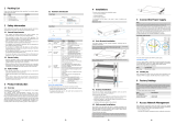
1 3 Board Diagram.
Back panel
Front panel
1 2
1Product Introduction
1 1 Overview.
1.2 Product Feature
The 16/24 ports PoE switch is an unmanaged PoE Ethernet switch along with
16/24 * 100Base-TX downlink PoE ports and 2 * 1000Base-TX uplink Ethernet
ports featuring 30-watt 802.3at PoE+ as well as 1 additional Gigabit Combo
port. The total PoE power budget is up to 250/370 watts. It supports web-based
PoE management and real-time PoE output LED display.The device can be
widely used in video security monitoring systems, network projects, etc.
Uplink
Gigabit Ports
Uplink
Gigabit SFP
Combo Port
PoE Output Ports
PoE Web
Management
Port
PoE Output
LED Reset
PoE Output
Percentage
LED
PoE Output Ports
Reset
PoE Web
Management
Port
PoE Output
LED
Uplink Gigabit
Ports
PoE Output
Percentage
LED
24 Por t s PoE sw itch
AC100~240V
Grounding Terminal
16 Por t s PoE sw itch
Provide 16 24x 100Mbps downlink PoE Ethernet ports, 2x gigabit uplink
Ethernet ports and 1x gigabit Fiber port;
Downlink Ethernet ports support PoE+, each port supports max. 30W output;
Support power consumption indication(LED indicates power output status);
support manage PoE on/off and power consumption setting via Web;
Accord with IEEE802.3、IEEE802.3u、IEEE802.3ab、IEEE802.3 af/at
standard;
4K MAC address,2.75Mb cache;
Quick installation, easy operation, convenient for wall-mounted、desktop
and rack installations.
/
Uplink
Gigabit SFP
Combo Port
CCTV
Mode
CCTV
Mode

1.4 Specification
Transmission distance is related with the cable, we suggest to use
standard Cat5e/6 network cable to get the best transmission result.
Products are subject to change without prior notice
3 4
Caution
2 Installation
2 1 Shipping List.
2.2 Installation Precautions
To avoid device damage or personal injury by improper use, please observe the
following precautions.
P
contact your local dealer.
lease check the following items before installation, if any missing, please
Item Name
Quantity
Unit
1 Device
1 Set
2 AC Power Line
1 Piece
4
Accessories
1 Set
3
User Manual
1 Piece
This is level A product, which may cause radio interference in living
environment. Users may need to take corresponding and effective
measures to solve the problem.
Anti counterfeiting label is attached to the injector's cover, so product
damage caused by unauthorized disassembly is not covered under
warranty.
-
2.2.1 Safety Precautions
Caution
Instruction
Item
Description
Product Type
Product Type
16ports
24ports
Port
Description
Downlink Ethernet Ports
16×RJ45,PoE+ 10/100Base-TX
24×RJ45,PoE+ 10/100Base-TX
Uplink Ethernet Ports
2*10/100/1000Base-T+1*1000Base-X(combo)
Power Input
1×AC Female Terminal
Grounding Terminal
1×Grounding Terminal
PoE&Power
Power Input
Mains on load,100~240VAC 50/60Hz
PoE Power Supply
End-span(1/2,3/6),IEEE802.3 af/at
PoE Max. Power Output
250W
370W(340W if 110V AC input)
Single Port Power Output&
Voltage
Single Port PoE Power Output≤30W, Voltage 54VDC
PoE Web
Management
PoE Management
Via Web( Default IP Address 192.168.1.200) to check, on/off and
adjust each port PoE output
Reset Button
PoE Web Reset
Long-press 3s, all Link LED solid on about 10s, switch reset to factory
default; short-press to restart.
One-key CCTV
CCTV Mode
1. Downlink ports only communicate with uplink ports;
2. Restrain network storm under 2Mbps;
3.Extend transmission distance to 250m
Network
Parameters
Network Standard
IEEE 802.3,IEEE 802.3u,IEEE 802.3 ab
Transmission Distance
100m(Max.)
Exchange Capacity
.7 2Gbps
8.8Gbps
Packet Transfer Rate
6.55Mpps
5.36Mpps
MAC Address
4K
Packet Data Cache
2.75Mb
Indicators
Status
Power Input
1x Red LED
Downlink Ethernet Ports
Link:16x Green LED
PoE:16x Yellow LED
Link:24x Green LED
PoE: 24x Yellow LED
Uplink Ethernet Port Link
2x Green LED
PoE Power Output Percent
10x LED(Including 7x Green, 2x Yellow, 1x Red), separately indicate
10%、20%~100%
Protection
Level
ESD
/ - -6KV 8KV, Per:IEC61000 4 2
Surge Protection
6KV, Per:IEC61000-4-5
Operation
Environment
Operation Temperature
- ℃~ ℃10 45
Storage Temperature
- ℃40 85℃~
Humidity(Non-condensing)
0~95%
Mechanics
Dimensions(LxWxH)
442 *207 *44.5mm mm mm
Material
Iron
Color
Black

5 6
Pull out the power plug before cleaning the switch. Do not use wet cloth nor
liquid to wipe or wash the switch;
Do not leave the switch close to water or wet place so as to prevent water or
dampness from entering into the switch;
Make sure the switch work in a clean environment. Excessive dust may
cause electrostatic adsorption, which will affect the equipment life and cause
communication failure;
The switch will work normally under the correct voltage. Please ensure the
voltage indicated on the switch corresponds to the power voltage;
To avoid the danger of electric shock, please do not open the switch case.
Do not open the switch case even if the switch is powered off;
The accessories (including but not limited to power lines, etc.), which can be
used for the switch only, is prohibited for other applications.
The device should work in indoor environment to avoid thunder stroke. It is
important to obey the following requirements no matter you install it in the
cabinet or on the workbench directly:
Enough space (larger than 10cm) for air outlet so as to facilitate the heating
dissipation;
Good ventilation system for cabinets and workbench;
Cabinet and workbench is sturdy enough to support the injector and it's
accessories's weight;
Cabinet and workbench have good grounding.
When it is working, the switch may be affected by external interference outside
the system through the ways of radiation and conduction. Please pay attention
to the followings:
AC power supply is TN system, so it is necessary to use single phase power
socket (PE) which can protect ground wire so that the filter circuit can
effectively filter out the power grid disturbances;
The switch should work far away from high-power radio transmitters, radar
transmitters, high-frequency devices;
Use electromagnetic shielding if necessary, such as shielded cable;
Interface cables should be arranged indoor rather than outdoor to prevent
over-voltage and over-current caused from damaging to the signal port.
2.2.2 Installation Requirements
2 2 3. . The Requirements of Electromagnetic Environment
There are 3 installation ways: rack, workbench and installation. wall-hung
Installation process
(1) Check rack grounding and stability;
(2) Use screws to fit hangers at the device board side;
:
Figure 2-1 Install hangers diagram
(3)
proper position
(4)
Put the device on the rack’s bracket and move the rack along the slot to
;
Use screws to fit the installation hanger at rack’s fixed slot, make sure the
device is installed at rack’s bracket steadily.
Figure 2 2- Install switch to the rack
Please pull out the power line before installing or moving the switch.
Grounding and anti-lightening can greatly increase the protection level of
the switch. please connect the earth terminal to the earth by using at least
wire 20.
Caution
2 3 . Installation Way
2 3 1. . Rack Installation

2.4.3 Power Line Connection
( ) he same as the power of
(2)
1 Check if the selected power is t ;switch
Connect one side of switch’s power line with the switch's AC power port,
and connect the other side with AC power socket;
(3)
Check if switch's AC power indicate light is on. The light means power
connected correctly.
2 4 Cable Connection.
2 4 1 Device Connection. .
U s e cr o s s ne t w o r k c a b l e o r cr o s s - o v e r ca b l e to co n n e c t P C o r
other device with switch's Ethernet port.
2 4 2 Configuration Cable Connection. .
Use a network cable to connect console port and management PC, use
management PC to configure the PoE switch.
This product’s installation hangers are just to fix the switch rather than
support it. Use brackets under the device (fixed to the rack) to support
switch when install the switch to the rack.
2.3.2 Workbench Installation
You can put this product on clean, stable, grounded workbench. The installation
procedure is as below:
(1)Put the device upside down carefully, clean the grooves on the chassis
backplane with soft cloth to make sure there is no oil or dust in it;
(2)Remove the stickers on the foot pad, paste the foot pad in backplane groove;
(3)Put the device upright on the workbench.
You also can put the product on clean, steady vertical wall. Installation
procedure is as below:
(1) Use the screws to fix the hangers;
2.3.3 Wall-hung Installation
(2) Drill holes on the solid position of wall and then drive the rubber plug into the
hole;
(3) Drive these screws into the hole for the rack and fix the product by aiming at
the rubber plug .
7 8
Figure 2-4
Fix the switch on wall
Figure 2-3 Hangers installation diagram
Instruction
Figure 2-5 Connect configuration cable
Figure 2-6 Power line connection

9 10
3 PoE Web Management Page
3.1 Preparation Work
3.2 Set Up Network Connection
3.2.1 Set Stastic IP Address of Managed PC
This product has Web management function which allows users to control and
manage PoE of each port by logging in on Web page.
(1) You need to set the management PC and this injector IP address under
the same network segment, this product’s default IP address is
192.168.1.200, gate is 255.255.255.0;
(2) If you need to connect remote network, please make sure the management
PC and the router can make this;
(3)This product can't assign the IP address for the management PC, you need
to set the management static IP by yourself.
Operation steps (take Windows XP as sample):
(1) Click <start> to enter the [start]
menu, select “control panel”. Double
click “network connection” icon,
double click the “local connection”
icon, pop out “local connection status”
window.
Make sure the management PC has already been installed with Ethernet adapter;
Use network cable to connect the console port with management PC.
Instruction
(2) Click <property> button, enter "local
connection property" window.
(3) Select "Internet protocol (TCP/IP), click
<property> button, enter “Internet protocol
(TCP/IP) property” window. Select “use
the IP address below” button, input IP
address( use arbitrary value between
192.168.1.1~192.168.1.254, besides
192.168.1.200) and the subnet
mask(255.255.255.0). Click"OK" to finish
the configuration.
DNS server address can be empty or be filled in with the real server
address.
Instruction

11 12
3 2 2 . . Confirm the Network Connection by Ping Command
Operation Steps as below:
(1)
menu, select [Run], pop out the dialog.
Click <Start> button to enter [Start]
(2)
<confirm> button. If there is equipment
response shown in the pop out dialog, that
means network connection succeed,
otherwise please check if the network
connection is correct.
Input "ping 192.168.1.200", click
3 2 3 . . Cancel the Proxy Server
If this management PC uses proxy server to visit the Internet, then you must prohibit
the proxy service, following is the operation:
(1) In browser, select [ tool/Internet
option] enter [Internet option] window.
3.3 Operating Guidance of Web
3 3 1 . . Start and Login
This p ro du ct w eb d ef au lt I P addre ss : 192.16 8. 1. 20 0, s ub ne t ma sk :
255.255.255.0, administrator account: admin, password:admin. After
installing the equipment correctly and setting up the computer, open the
browser, input the injector default address in the browser address bar:
, then press the Enter key, the user login page will show in
front of you as follows:
http://192.168.1.200
The browser version recommended:IE7 and later, Firefox browser, Chrome, 360
browser (IE7 and later).
(2) Select connection tabs in [Internet
option] window, and click [LAN Setting]
button.
“ ”
(3) Make sure the “Use proxy server for LAN”option is not selected. If selected, please
cancel it and click <yes> button.

The diagram of language change page
3 3 2 2 Setting IP Address. . .
(1) Click the Web management page
menu bar “IP”, then It will popup a
dialog box of setting IP address.
3.3.2 Operating Instruction of Web
3 3 2 1 Change Language. . .
As shown in the picture below, press the drop-down list at the icon , choose
“Chinese” or “English” to achieve Web page language, as the picture below.
(2) Change product IP address, subnet
mask and gateway at the dialog box of
setting IP address, such as change the
IP address to 192.168.2.200, keep
subnet mask unchanged, and change
default gateway to 192.168.2.1.
(3) After changing the IP address, press the “OK” button and wait for 10 seconds
till product IP address is successfully changed.
13 14
After inputting the correct user name and password, click <Login> and the
browser will show the product Web management page as the picture below:
Please follow the steps to check if the injector is installed correctly:
(1) Whether the physical connection of the equipment is correct?
The other end of the network line that is connected with computer
network card must connect with the injector Console port, and ensure the
link indicator light of the network port is on.
(2) Whether the computer TCP/IP agreement setting is correct?
Your computer ’s IP address must be 192.168.1.x (x range is1~254
and x cannot be 200, it will conflict with the product IP
address: 192.168.1.200), subnet mask: 255.255.255.0
otherwise
.
Caution
Diagram of Web English management page

What to do when the password is forgotten?
Please refer to 3.2.2.4 to restore IP address and password.
3.3.2.4 Restore the Initial Setting
(1) Click menu bar [restore the initial setting] on the Web page, popup dialog box as
shown below:
Restore the initial setting
(2) Click <Ok> button and restore the initial setting, press <Cancel > button to
cancel the restore of the initial setting.
(3) After pressing <Ok> button, wait for 10 seconds, the product restores the
initial setting.
To restore the initial setting means to restore two menu configuration
information of [PoE setting] and [Port status and control] in the Web to
factory default setting, please use in caution.
15 16
(1) When product IP address is changed, please ensure that the computer IP
address and the product IP address must be in the same network segment
and the settings of subnet mask and gateway must be correct.
(2)When changing product IP address, please ensure the power supply to
avoid abnormal problems.
(3)What to do if you forget the IP address of the product? Please refer to
3.3.2.5 restore the initial setting.
3.3.2.3 Change Password
Login password: the product only provides one user name “admin”,default
password is “admin”,
and the password length must be between 5~20,
Please change the password in time for system safety
The change will take effect
on next login.
(1)Click the Web management page
menu bar [change password], then It
will pop up a dialog box of changing
password.
(2 ) E nt e r the pr o du ct cu r re nt
password and the new password,
then confirm the new password.
(3)Click the <ok> key and then a
dialog box as the picture will pop
up, click <Close>.
Caution
Caution
Caution

(1) Power input: The total power provided by the product for PoE supply, i.e. the
power provided by built-in 54V power, has been set up when it leaves the factory,
please do not modify it. If users modified the power supply, please correct this
setting. If the setting value is larger than the actual power of the built-in power
supply, there will be a damage of built-in power. If the setting value is smaller than
the actual power of built-in power supply, built-in power supply could not be fully
allocated out.
(2) Allowing maximum overload: built-in power allows overload value setting range
is 0%-10%, default is 5%. If actual power is too large that cause built-in power
overload exceeding setting value, the system will turn off power supply of low
priority ports. For example:when input power is 360w, maximum overload is 5%.
when actual output power exceeds 360*(1+5%)=378w , the system overloads.
(3) Power Reservation: power reservation could not be contributed, but be used for
PoE equipment consumption due to load changes. Default power reservation is
15% of total power. The higher the value, the slower the risk of system overload, the
power to be contributed decreases, and the number of PoE equipments to be
connected decreases; on the contrary , the more the number of PoE equipments to
be connected, the higher risk of system overload.
(4) Operation instructions: after setting the value, press <OK> button. Setting
succeeds when the following window pops out.
3.3.2.9 Power Status
Power status page diagram
The input power, allowing maximum overload and reserved power have
been set up before the product leaves the factory. User is allowed to modif
it, prudently.
3.3.2.8 PoE Setting
Diagram of PoE setting page
3 3 2 5 Restore IP Address and Login Password. . .
Start the product, unplug the network cable of console port, then press init
key(3~5 seconds), till the RJ45 LED light of console port flash once, the IP
address and login password will be restored to the initial setting.
3 3 2 6 Equipment Information. . .
Click menu bar [equipment information] on Web page , then three product
information of [IP address], [MAC address] and [software version] will be popped
out for user checking. After review, click <Exit> to log out checking status.
Equipment information diagram
3 3 2 7 Exit. . .
Click main menu [ Exit] to return to login page.
Diagram of restore IP address, login password
17 18
Instruction
PoE Output Ports
PoE Web
Management
Port
PoE Output
LED Reset
PoE Output
Percentage
LED

(3) Priority: there are three port power supply priority levels: low, medium and
high. when system overloads, the power supply of low priority port will be
disconnected firstly.
(4) Allowed maximum output power: set single port’s limited output power, the
port will be disconnect with power supply once actual power exceeds this value.
Each port of the product provides max 30W output power. If user setting exceeds
30W, the maximum output power will only be 30W.
(5) Actual output power: port’s actual output power .
(6) Fault status alarm: The following situations will cause warning information on
[prompted message]:
Surplus power lower than 10W;
Total power overloads ;
Linked PoE powered device’s (PD) port disconnected.
(7) Operation instructions:
Open all the ports: press title
bar , then popup dialog
box as the figure shown:
Open single port: press corresponding port , after setting success,
popup“setting success”promp, and the corresponding button becomes
the system will check whether the port is connected with PoE powered
device (PD) automatically. It starts power supply when checking OK.
Close single port: press corresponding port and popup dialog box.
Take port 1 as an example, press <OK>, popup “setup is successful”. When
setting succeeds, corresponding button becomes .
(1) Actual output: total actual output power .
(2) Surplus: the power to be used for redistribute. Surplus=input-actual output-
reservation, please noted that the product distributes power according to power
level of detected PoE powered device when connecting a new PoE powered
device, instead of according to the actual power of newly connected PoE
powered device. For example: when surplus power is 20W , if the power level of
the connected PoE powered device is 25.5W, the system could not distribute
power for it even if the actual power only need 10W, which means it cannot be
powered.
(3) Reservation: used for PoE powered device due to load changes caused by
consumption, from parent menu setting “input power * reserve power”.
(4) input : The total power of the system, from parent menu “input power” .
3 3 2 10 Port Status and Control. . .
Port status and control page diagram
(1) Port number: corresponding to the port numbers on product board,
indicates unlinked PoE powered device or linked PoE powered device without
power supply, indicates linked PoE powered device and normal supply.
(2) Powered device location: a brief description of installation location of
powered device’s each port.
19 20

Please find the following solution when the device doesn’t work
Please confirm the installation is correct
Please confirm whether the sequence of RJ45 cable meet the EIA/TIA568A or
568B industry standards;
Please replace device which can not work with a properly working one to check
whether the device is broken;
Please contact the factory if the problem stays unsolved.
;
Turn off all the ports: press title bar button, popup dialog box as
shown below:
Press OK ,when all the ports open, popup “setup is successful” , the
button become status.
Setting single port parameters : port parameters include powered device
location, priority and allowed maximum output power. After setting
parameters, press <OK> button of the corresponding port, then popup
“setting success” when operation finishes .
Setting all the port parameters : press [port control and status] [actual output
power(W)] button, then popup dialog box as shown below:
< >
Press OK when all the setting finishes, popup “setup is successful”.
Setting unified allowed maximum output power: as shown below:
< >,
After selecting the check box, all the ports allow maximum output power
depends on this value.
Press <OK>, when all the port opens, popup “setting success”, the button turns
to status.
21 22
3 5 Trouble Shooting.
3.4 Typical Application
This product design is environmental friendly. Please store, use and discard
this product in accordance with the relevant national legal/ regulatory
requirements.
Environment protection
Cat5/5e/6
LCD display
NVR
switch
UTP1-SW24-TP420
Fiber
PoE camera
PoE camera
PoE camera
PoE camera
/