Futaba GYA553 User manual

Type
User manual

Futaba GYA553 is a high-performance airplane gyro system designed to stabilize and enhance the flight characteristics of your aircraft. With its advanced 3-axis MEMS sensor technology, the GYA553 provides precise and reliable attitude control, ensuring a more stable and enjoyable flying experience. It features adjustable gyro gain, multiple mounting options, and compatibility with a wide range of Futaba transmitters, making it a versatile solution for various aircraft types and skill levels.

Futaba GYA553 is a high-performance airplane gyro system designed to stabilize and enhance the flight characteristics of your aircraft. With its advanced 3-axis MEMS sensor technology, the GYA553 provides precise and reliable attitude control, ensuring a more stable and enjoyable flying experience. It features adjustable gyro gain, multiple mounting options, and compatibility with a wide range of Futaba transmitters, making it a versatile solution for various aircraft types and skill levels.

2
3
1
3
2
4
On the home screen, basic information such as gyro operation mode,
sensitivity, battery voltage are displayed.
Gyro operation mode / Gyro
gain
Displays "AVCS" or "Normal"
opera-tion mode and gyro
gain of aileron (roll), elevator
(pitch) and rudder (yaw) axis.
GYA553 Software version
Battery voltage
Displays the voltage of the
receiver battery connected to
GYA.
The software version of
the connected GYA553 is
displayed.
5
Set the mounting direction of GYA. Set mounting direction
ZLWKUHIHUHQFHWR¿JXUHEHORZ
Set with the wing type/tail type of GYA553. The wing type/tail type of the transmitter is not used and is normal.
7XUQR൵WKHHOHYRQ9WDLOPL[LQJRQWKHWUDQVPLWWHUVLGH
'RQRWXVHWUDQVPLWWHUVXEWULP$GMXVWXVLQJWKHJ\URQHXWUDOR൵VHW
:KHQXVLQJWKH6%86VHUYR\RXFDQDOVRXVHWKHQHXWUDOR൵VHWIXQFWLRQRIWKH6%86VHUYRVHWWLQJSDUDPHWHUV
6
Select the servo type according to the servo to be
used.
7KHVWDELOLW\RIGLJLWDOVHUYRPRGHRIDIOLJKW
LQFUHDVHVLQ RUGHUWR SHUIRUPD KLJKVSHHGFRQWURO
action.
Select the SB/R2 port.
7
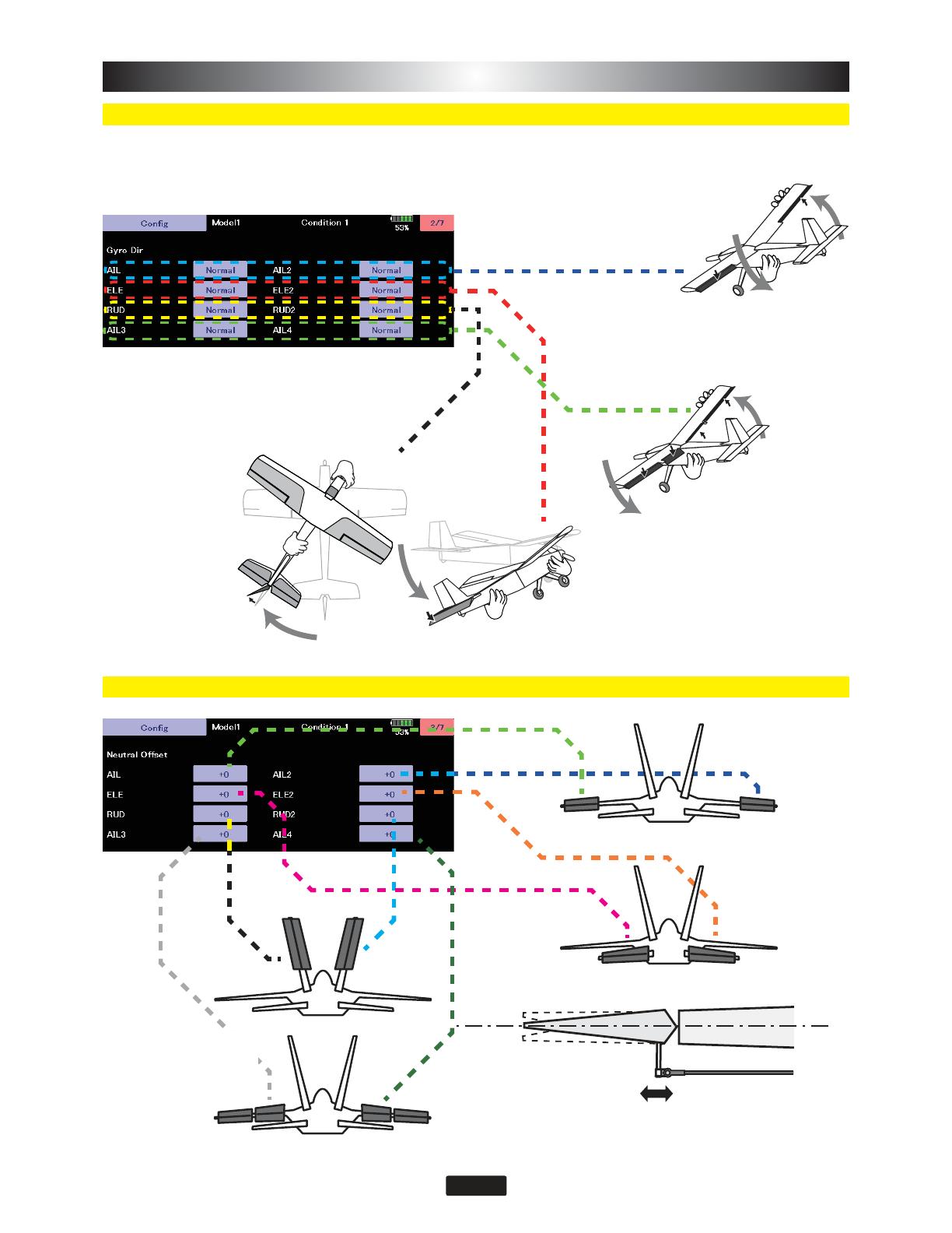
Neutral position setting for each servo.
It is the direction settting of the gyro. Be careful as it will crash if the direction is reversed.
For dual aileron, dual elevator, and dual rudder aircraft, check the operating direction of each second
aileron/elevator/rudder.
If the SB/R2 port output is set to
"S.BUS(HS)" or "S.BUS(STD)", the
setting menu will display AIL3 and
AIL4 setting items.
* AIL3 and AIL4 settings cannot be
set with the button settings on the
GYA553 main unit.
* AIL3 and AIL4 settings cannot be
set with the button settings on the
GYA553 main unit.
If the SB/R2 port output
is set to "S.BUS(HS)" or
"S.BUS(STD)", the setting
menu will display AIL3 and
AIL4 setting items.
8
This is the limit setting for each servo. The
SRVLWLRQRIWKHPD[LPXPRSHUDWLRQLVUHDGLQWRWKH
J\URLQWKH¿UVWVHWWLQJ
If the SB/R2 port output is set to "S.BUS(HS)"
or "S.BUS(STD)", the setting menu will display
AIL3 and AIL4 setting items.
* AIL3 and AIL4 settings cannot be set with the
button settings on the GYA553 main unit.
9
Reset each Config item. It returns to the initial
value.
The current rate numbers C1 to C5 are displayed by operating the channel of the transmitter.
/LNH WKH ÀLJKW FRQGLWLRQ IXQFWLRQ RI WKH WUDQVPLWWHU \RX FDQ VHW XS WR  GL൵HUHQW GDWD IRU WKH DWWLWXGH
KROGLQJIRUFHUDWHRIWKHDLUFUDIWLQ$9&6PRGHE\RSHUDWLQJWKHVZLWFKIURPWKHWUDQVPLWWHUDQGVZLWFK
between them. You can set the holding power rate selector switch to the channel with the AFR function of
the transmitter, and set the point for each rate on the AFR point curve to switch. It is also possible to use
WKHÀLJKWFRQGLWLRQIXQFWLRQWRZRUNZLWKWKHÀLJKWFRQGLWLRQVZLWFK
When set to SW of DG1 or DG2
Switch channel rate
Channel rate
When set to dial or lever
,WLVDIXQFWLRQWRDGMXVWWKHSRVWXUHKROGLQJIRUFHRIWKHDLUFUDIWLQ$9&6PRGH
Decreasing the value weakens the holding power and makes the operation feeling closer to the normal
mode.
10
The channel of each function can be changed.
Set the CH for each function according to the transmitter to be used. Any unused functions should be set
to INH (Inhibited).
CH setting items for AIL3 and AIL4 are displayed on the
¿QDOVFUHHQRIWKH6%86EDVLFVHWWLQJVFUHHQ%\VHWWLQJ
WKHRSHUDWLRQ&+RI$,/DQG$,/WKHJ\URFRQWUROOHG
signal is output to the corresponding CH of the S.BUS
output.
* Match the operation CH and CH setting on the function setting screen
on the transmitter side.
*When the AIL3 and AIL4 CH settings are INH, the gyro control is not
performed and the data sent from the transmitter is output as is.
  • Page 1 1
  • Page 2 2
  • Page 3 3
  • Page 4 4
  • Page 5 5
  • Page 6 6
  • Page 7 7
  • Page 8 8
  • Page 9 9
  • Page 10 10
  • Page 11 11

Futaba GYA553 User manual

Type
User manual

Futaba GYA553 is a high-performance airplane gyro system designed to stabilize and enhance the flight characteristics of your aircraft. With its advanced 3-axis MEMS sensor technology, the GYA553 provides precise and reliable attitude control, ensuring a more stable and enjoyable flying experience. It features adjustable gyro gain, multiple mounting options, and compatibility with a wide range of Futaba transmitters, making it a versatile solution for various aircraft types and skill levels.

Ask a question and I''ll find the answer in the document

Finding information in a document is now easier with AI