Mounting to the Airplane
Servo
Gyro reverse
Recovery mode
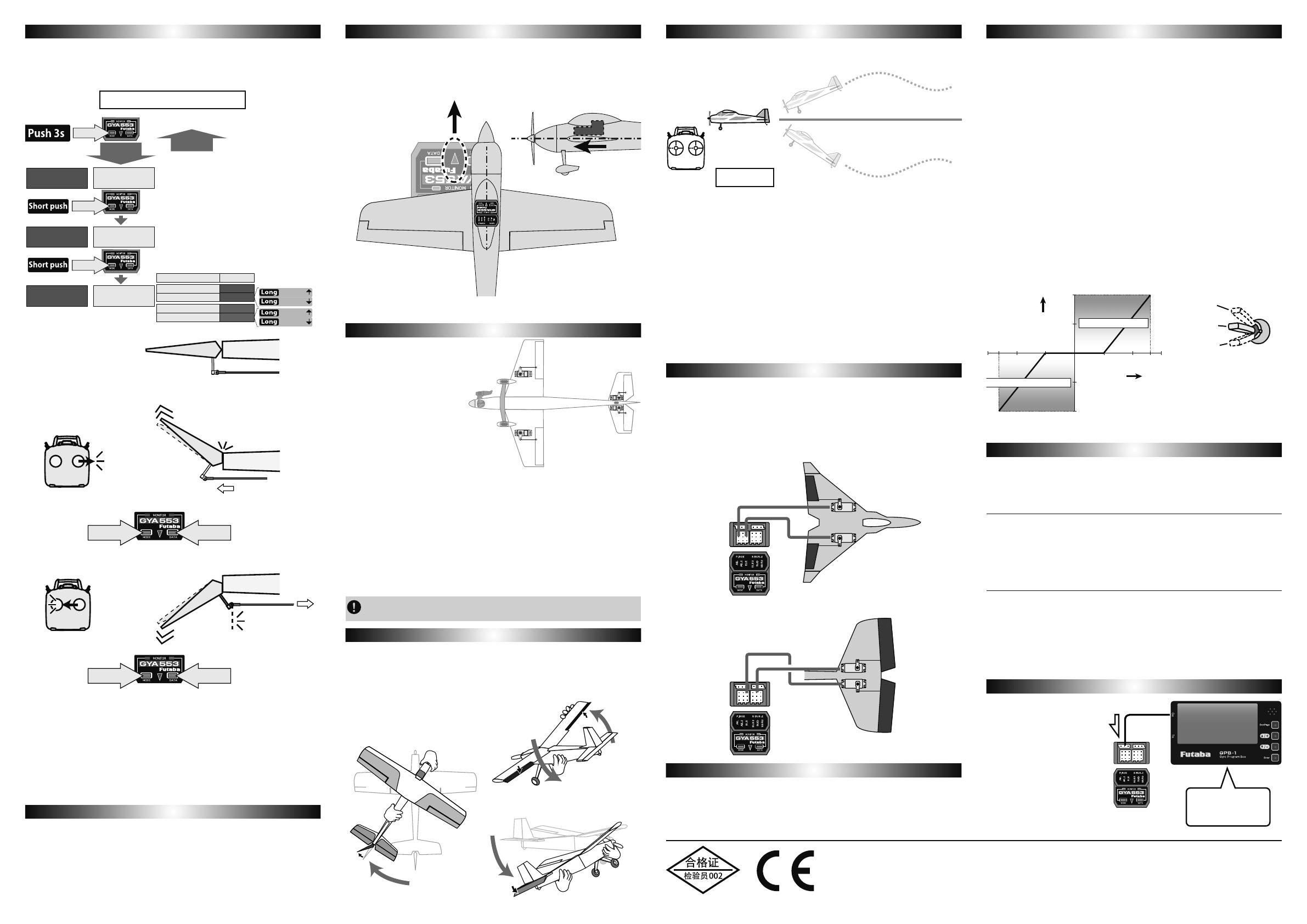
ELEVON/V-TAIL Connection
Limit setting
Flight Adjustment
Servo Operation on the Ground
Servo Operation on the Ground
Gyro Program Box
GYA553 Update
It is the direction setting of the gyro. of the 3
axes. Be careful as it will crash if the direction is reversed.
For dual aileron, dual elevator, and dual rudder aircraft, check the operating
direction of each second aileron/elevator/rudder.
By turning on the CH10 switch of the transmitter, it is possible to automatically
return to level flight. It is used in the unlikely event that you lose track of the
direction of the aircraft. NORMAL / AVCS / GYRO OFF Recovery mode starts in
any state.
This is the limit setting for each servo. The position of the maximum operation
LV UHDG LQWR WKH J\UR LQ WKH ¿UVW VHWWLQJ 6HW WR HDFK RI WKH D[HV ZLWK
.
If the servo operates more than the maximum operating position, the servo and
linkage will be overloaded and may be damaged. To prevent this, be sure to set this
limit on all servos at the time of initial setting.
Connect the separately sold gyro
program box GPB-1 to the P.BOX
port of GYA553, you can set the
parameters of GYA553 in the
program box. However, GPB-1
needs to be updated for GYA553
from the Futaba website. (CIU-3
/ 2 is required) For details, refer
to the Futaba website.
GYA553 can be updated from a PC by connecting the separately sold CIU-3 / 2.
3OHDVHFKHFNWKH)XWDEDGHDOHULQ\RXUFRXQWU\ZHEVLWHIRUWKHODWHVW¿UPZDUHDQG
update method.
Firmly stick the gyro to the fuselage with the double sided tape supplied. Install the
gyro at a level place near the center of gravity where there is little vibration. It can
also be installed at the side or rear of the fuselage. In this case, change the gyro
mount direction setting.
*Depending on the airframe material such
as balsa, etc., the adhesive strength of the
double sided tape may drop. In this case,
prepare the mounting surface well.
*Do not use a product other than the double
sided tape supplied. Vibration may result,
causing the plane to become uncontrollable.
Gyro Sensitivity and AVCS Switching
Gyro Sensitivity and AVCS Switching
The gyro has two operation modes: NORMAL mode and AVCS mode.
In the AVCS mode, angle control is performed at the same time as NORMAL
mode rate (rotating speed) control.
In the AVCS mode, the neutral keeping force is stronger than the NORMAL
PRGHDQG WKHÀLJKW DWWLWXGHRI WKHDLUFUDIW LVIRUFHIXOO\ PDLQWDLQHG'XULQJ NQLIH
edge flying, idiosyncrasies of the aircraft when climbing will be compensated
automatically. On the other hand since the rudder follows when the aircraft stalls,
pay special attention to the elevator axis. To be safe, switching to the NORMAL
PRGHZKHQWDNLQJR൵DQGODQGLQJLVUHFRPPHQGHG
When the remote gain function is used normally and AVCS mode switching is
performed in accordance with the direction of operation of the transmitter's remote
gain channel. At the + rate side, the AVCS mode is selected and at the – rate side,
the NORMAL mode is selected. The sensitivity is changed by adjusting the end
point rate. If the transmitter has a gyro sensitivity setting mixing function, the
sensitivity setting is performed directly. The sensitivity setting criteria by end point
LVVKRZQLQWKH¿JXUHEHORZ7KHVHQVLWLYLW\EHFRPHV]HUREHWZHHQHQGSRLQW
WRDQGEHFRPHVDWHQGSRLQW5HIHUWRWKHWUDQVPLWWHULQVWUXFWLRQ
manual and set the end point. When AVCS is used, setting the 3-positions switch to
the sensitivity CH (there are types which cannot be set by transmitter) and setting it
as shown above is recommended. In the case of a 2-positions switch, inhibiting the
J\URDWVHQVLWLYLW\VXFKDV1250$/PRGHDQGVHQVLWLYLW\DQG$9&6PRGH
DQGVHQVLWLYLW\LVVDIH
Selection of an analog and digital servo is performed in a palameter settings.
7KHVWDELOLW\RIGLJLWDOVHUYRPRGHRIDÀLJKWLQFUHDVHVLQRUGHUWRSHUIRUPDKLJK
speed control action.
Link the servo in accordance with the kit
instruction manual. Adjust the linkage
rod so that the trim amount is as small as
possible.
During aileron mode operation the 2nd
aileron servo moves in the same direction
as the aileron servo. In the elevator
mode, the 2nd elevator servo moves in
the opposite direction of the elevator
servo. Mount the servos as left and right
objective linkage.
$GMXVWWKHWUDQVPLWWHUDQGJ\URZKLOHUHSHDWHGO\WDNLQJR൵DQGODQGLQJDQGZLWKWKH
aircraft on the ground.
Transmitter adjustments must not be made
ZKLOHÀ\LQJEHFDXVHLWLVGDQJHURXV
)O\ WKH DLUFUDIW DQG WULP LW E\ WXUQLQJ R൵ WKH J\UR DW VHQVLWLYLW\ RU LQ WKH
1250$/PRGH$IWHUWULPPLQJVZLWFKWKHJDLQVZLWFKEHWZHHQVHQVLWLYLW\
(or NORMAL mode) and the AVCS mode three times at an interval of within
one second and then set the gain switch to the AVCS mode position. This
memorizes the AVCS mode neutral trim position at the gyro. In the AVCS mode,
GRQRWSHUIRUPWULPPLQJGXULQJÀLJKW
$GMXVW WKH J\UR VHQVLWLYLW\ VR WKDW KXQWLQJ GHÀHFWLRQ RI WKH DLUFUDIW LQ VPDOO
increments) does not occur in the control axis direction. The gyro sensitivity is
GL൵HUHQWGHSHQGLQJRQWKHDUHDRIWKHDLUFUDIWUXGGHUDLUVSHHGDQGJ\URXVHG
,QLWLDOO\ WU\ FKDQJLQJ WKH VHQVLWLYLW\ LQ VWHSV ,I KXQWLQJ LV H[FHVVLYH WKH
aircraft may be damaged. Hunting tends to stop when the airspeed is lowered.
If the stick is moved when the airplane is on the ground, the servo will move to the
limit position. In the AVCS mode, the servo will not return to the neutral position
even if the stick is set to the neutral position, but this is normal.
If the stick is moved fully to the left or right three or more times within one second,
the servo will temporarily return to the neutral position.
FUTABA CORPORATION
Hobby Radio Control Business Center Sales & Marketing Department
1080 Yabutsuka, Chosei-mura, Chosei-gun, Chiba-ken, 299-4395, Japan
TEL: +81-475-32-6051, FAX: +81-475-32-2915
©FUTABA CORPORATION 2020, 12 (1)
7XUQR൵WKHUHFRYHU\VZLWFKZKHQUHWXUQWROHYHOÀLJKW,WZLOOEHDQRUPDOÀLJKW
Set with the wing type of GYA553. The wing type of the transmitter is not used and
is normal.
Ɣ7XUQR൵WKHHOHYRQ9WDLOPL[LQJRQWKHWUDQVPLWWHUVLGH
Ɣ'RQRWXVHWUDQVPLWWHUVXEWULP$GMXVWXVLQJWKHJ\URQHXWUDOR൵VHW
Ɣ:KHQXVLQJWKH6%86VHUYR\RXFDQDOVRXVHWKHQHXWUDOR൵VHWIXQFWLRQRIWKH
S.BUS servo setting parameters.
Maneuvering is possible even when the recovery switch is ON, but the operation
GL൵HUVDVIROORZV
Ɣ:KHQWKHUHFRYHU\VZLWFKLV21UHOHDVHWKHVWLFNWRQHXWUDODQGWKHDLUFUDIWZLOO
EHLQOHYHOÀLJKW
Ɣ:KHQWKHUHFRYHU\VZLWFK LV21WKHUROO DQGSLWFK WLOWDQJOHLVOLPLWHGWR
ZKHQ WKH WUDQVPLWWHU WUDYHO UDWH LV ,QYHUWHG ÀLJKW LV QRW SRVVLEOH
Decreasing the travel rate of the transmitter will reduce the maximum tilt angle
of the aircraft. The maneuvering feels dull and the turning radius increases. If
WKHUHFRYHU\VZLWFKLVWXUQHGR൵ZKHQWXUQLQJWKHRSHUDWLRQZLOOVXGGHQO\WDNH
effect and the aircraft will tilt and become dangerous. Turn off the recovery
switch when the stick is in neutral.
Ɣ:KHQWKHUHFRYHU\VZLWFKLV21WKH02'(/('ÀDVKHVZKLWH
Ɣ$PRPHQWDU\W\SHVZLWFKLVUHFRPPHQGHGIRUWKHUHFRYHU\PRGH
When you use an analog servo, please be sure to set to AN : 70 Hz. If it sets to
DG : 285 Hz and it is operated, there is a danger that a servo will be destroyed.


