Page is loading ...

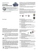
TopWorx™ TV-Series Valve Controllers
Installation, Operation & Maintenance Manual

Emerson's technology know-how and application experience
enable us to develop products and solutions that deliver the
proven performance and reliability our customers expect
when looking to build, connect, improve, and maintain
their equipment and automation process.
Emerson™
Emerson is a powerful, global, single source of process improvement technology and
expertise. We help major companies optimize their plants and processes to achieve
higher quality, greater reliability and faster time to market, while steadily advancing
productivity and profitability.
Driven Without Compromise

Table of Contents
Table of Contents ……………………………………………………….
2
Installation on Actuator………………………………………………. 3
Normal and Reverse Acting…………………………………….. 3
Mounting.…………………………………………………………….. 3
TVA (Domed Lid) Dimensions and Materials………………….. 4
TVF (Domed Lid) Dimensions and Materials…………………... 5
TVL (Domed Lid) Dimensions and Materials ………………….. 6
TVH (Domed Lid) Dimensions and Materials………………….. 7
TVL (Flat Lid) Dimensions and Materials………………………... 8
TVH (Flat Lid) Dimensions and Materials ………………………. 9
Shaft Detail ………………………………………………………………..10
Sensors Basic Function ………………………………………………..11
Switch Setting ……………………………………………………… 11
GO™ Switch Push To Set Targets …………………………….12
Switch Option Q/G ………………………………………………….13
Switch Option M …………………………………………………...14
Switch Option T …………………………………………………….15
Switch Option R …………………………………………………….15-16
Switch Option P …………………………………………………….16-17
Switch Option QS/RS/PS/MS/KS/LS: TV-LED with SPDT
Proximity Switches ………………………………………………..18
Switch Option E …………………………………………………….19
Switch Option 42 and 52 ………………………………………..20
Switch Option AM/AS: AS-I ……………………………………. 21-22

3
Installation on Actuator
Normal and Reverse Acting
Normal acting is full clockwise (CW) when the process valve is closed and counter-clockwise (CCW) when the process valve is open. Reverse
acting is full CW when the process valve is open and CCW when the process valve is closed.
Indicator dome assemblies are designed to accommodate both Normal and Reverse Acting units. When the unit is Reverse
Acting, the indicator dome assembly will have to be rotated.
The image to the right shows a TopWorx unit mounted parallel to the process valve in the
closed position. The green arrow at the top shows the “normal acting” direction of travel to
open the valve. This is the standard orientation of your unit unless otherwise specified and will
be factory set to operate in this fashion.
Installation on Actuator
Mounting
TopWorx has numerous mounting bracket kits available to meet your specific application,
whether rotary or linear. Consult your local distributor or factory representative for ordering
information. The illustration shows a direct Namur mount on a quarter turn valve. Refer to
your mounting kit documentation for specific mounting instructions.
Installation Notes
1. Remove the upper housing of the unit to allow access to the target cam assembly.
2. Hold the unit above the mounting surface in the orientation in which you intend to mount.
Rotate the shaft to align the tang with the actuator slot. In some cases it may be necessary to
rotate the target cam on the shaft to allow assembly. For most units the target cam is secured
with a compression spring. Simply grasp the cam, push down, and realign the cam as re-
quired. On some units the target cam is secured with a snap ring. On these units the removal
of the shaft from the base assembly will be required to change the orientation. Once re-
moved from the base assembly, remove the snap ring securing the target cam and rotate as
required.
3. Use caution not to allow undue axial (thrust) load on the shaft.
4. Cycle the valve a couple of times prior to final tightening of the mounting kit hardware.
This allows the shaft to self-center in the pinion slot, or coupler. Refer to the dimensions and
materials section of this document for appropriate tightening torque.
5. Always use sound mechanical practices when torquing down any hardware or making
pneumatic connections.
Refer to the Integrated Pneumatic Control Valves section for detailed information on pneu-
matic connections.
6. This product comes shipped with conduit covers in an effort to protect the internal compo-
nents from debris during shipment and handling. It is the responsibility of the receiving and/
or installing personnel to provide appropriate permanent sealing devices to prevent the intru-
sion of debris, and moisture, when stored outdoors or when installed.
7. It is the responsibility of the installer, or end user, to install this product in accordance with
the National Electrical Code (NFPA 70) or any other national or regional code defining proper
practices.

4
Dimensions and Materials: TopWorx TVA (Domed Lid)
MATERIALS OF CONSTRUCTION
Enclosure Lexan 123R UV F1 Rated
Fasteners
304 Stainless Steel standard
316 Stainless Steel optional
Shaft
304 Stainless Steel standard
316 Stainless Steel optional
Indicator Dome Lexan 123R UV F1 Rated
Seals
Nitrile/EPDM/Silicone (Other materials
available upon request)
Fastener Torque Specifications
Enclosure Housing Bolts 224 in-oz [1,582 mN·m] +/- 10%
Indicator Dome Screws 200 in-oz [141 mN·m]
Mounting Holes 4 ft-lbs [5.4 N·m] +/- 10%

5
Dimensions and Materials: TopWorx TVF (Domed Lid)
MATERIALS OF CONSTRUCTION
Enclosure
Cast A360 aluminum with dichromate
conversion coating inside & out, epoxy
coated exterior rated for 1,000 hrs salt
spray per ASTM B117
Fasteners
304 Stainless Steel standard
316 Stainless Steel optional
Shaft
304 Stainless Steel standard
316 Stainless Steel optional
Shaft Bushing ASTM C83600 Bronze
Indicator Dome Lexan 123R, UV F1 rated
Seals Silicone
Maximum Fastener Torque Specifications
Enclosure Housing Bolts 8 ft-lbs [10.8 N·m]
Indicator Dome Screws 200 in-oz [141 mN·m]
Bottom Mounting Holes 10 ft-lbs [13.6 N·m]

6
Dimensions and Materials: TopWorx TVL (Domed Lid)
MATERIALS OF CONSTRUCTION
Enclosure
Cast A360 aluminum with dichromate
conversion coating inside & out, epoxy
coated exterior rated for 1,000 hrs salt
spray per ASTM B117
Fasteners
304 Stainless Steel standard
316 Stainless Steel optional
Shaft
304 Stainless Steel standard
316 Stainless Steel optional
Shaft Bushing ASTM C83600 Bronze
Indicator Dome Lexan 123R, UV F1 rated
Seals Silicone
Maximum Fastener Torque Specifications
Enclosure Housing Bolts 8 ft-lbs [10.8 N·m]
Indicator Dome Screws 200 in-oz [141 mN·m]
Bottom Mounting Holes 10 ft-lbs [13.6 N·m]

7
Dimensions and Materials: TopWorx TVH (Domed Lid)
MATERIALS OF CONSTRUCTION
Enclosure Stainless Steel, 316
Fasteners
304 Stainless Steel standard
316 Stainless Steel optional
Shaft
304 Stainless Steel standard
316 Stainless Steel optional
Shaft Bushing ASTM C83600 Bronze
Indicator Dome Lexan 123R, UV F1 rated
Seals Silicone
Maximum Fastener Torque Specifications
Enclosure Housing Bolts 8 ft-lbs [10.8 N·m]
Indicator Dome Screws 200 in-oz [141 mN·m]
Bottom Mounting Holes 10 ft-lbs [13.6 N·m]

8
Dimensions and Materials: TopWorx TVL (Flat Lid)
MATERIALS OF CONSTRUCTION
Enclosure
Cast A360 aluminum with dichromate
conversion coating inside & out, epoxy
coated exterior rated for 1,000 hrs salt
spray per ASTM B117
Fasteners
304 Stainless Steel standard
316 Stainless Steel optional
Shaft
304 Stainless Steel standard
316 Stainless Steel optional
Shaft Bushing ASTM C83600 Bronze
Indicator Dome Lexan 123R, UV F1 rated
Seals Silicone
Maximum Fastener Torque Specifications
Enclosure Housing Bolts 8 ft-lbs [10.8 N·m]
Indicator Dome Screws 200 in-oz [141 mN·m]
Bottom Mounting Holes 10 ft-lbs [13.6 N·m]

9
Dimensions and Materials: TopWorx TVH (Flat Lid)
MATERIALS OF CONSTRUCTION
Enclosure Stainless Steel, 316
Fasteners
304 Stainless Steel standard
316 Stainless Steel optional
Shaft
304 Stainless Steel standard
316 Stainless Steel optional
Shaft Bushing ASTM C83600 Bronze
Indicator Dome Lexan 123R, UV F1 rated
Seals Silicone
Maximum Fastener Torque Specifications
Enclosure Housing Bolts 8 ft-lbs [10.8 N·m]
Indicator Dome Screws 200 in-oz [141 mN·m]
Bottom Mounting Holes 10 ft-lbs [13.6 N·m]

10
Dimensions and Materials: Shaft Detail

11
Sensors: Basic Function
Each T-Series unit is equipped with 2 or 4 adjustable targets with a usable range between 90° and 45°. For normal acting applications the
targets are color coded red for closed and green for open. The color code would be reversed for reverse acting units. After installing the unit
on the actuator or valve assembly, the targets must be set.
Normal acting
1. Rotate the valve full CW to the closed position.
2. Twist the red target or press and move the metal target CW or CCW as required to engage the switch (refer to the specific
switch section for testing and confirmation information about your switch type).
3. Rotate the valve full CCW to the open position.
4. Twist the green target or press and move the metal target CW or CCW as required to engage the switch (refer to the spe-
cific switch section for testing and confirmation information about your switch type).
Reverse acting
1. Rotate the valve full CW to the open position.
2. Twist the red target or press and move the metal targets CW or CCW as required to engage the switch (refer to the spe-
cific switch section for testing and confirmation information about your switch type).
3. Rotate the valve full CCW to the closed position.
4. Twist the green target or press and move the metal target CW or CCW as required to engage the switch (refer to the
specific switch section for testing and confirmation information about your switch type).
Setting Switches
Unlock green and red targets. Stroke the actuator open and closed to ensure there is no obstruction in it’s stroke. Once actuator is at the
desired position, twist the knob on the cam or press and move the metal target until the switch is made and lock the appropriate target.
The red knob is for the closed position and the green is for the open position (normal acting).
Warning: Strikers are spring loaded and may eject forcefully upon disassembly. Use caution when disassembling.
For switching angle under 45° (for red and green twist knobs only)
When the switch box is mounted to a linear actuator or
when the actuator strokes less than 45°, we recommend the following:
1. Remove shaft from switch box by removing the circlip underneath the switch box
2. Remove the circlip underneath the cam if equipped, then push the cam down the shaft by 3-4mm and turn it 90°
3. Push the cam back up, you will see the flats fit snugly between the locating lugs inside the hub
4. Replace the circlip
5. Remove the closed switch from the bracket and install it on the inside of the bracket next to the open switch
To re-assemble:
1. Replace the screws with M3 X 25mm long screws
(insert through both switches and bracket and fasten
with the nut on the inside closest to the switch box bearing)

12
Target assembly for 90° rotation
*CAM SHOWN IN CLOSED POSITION
Target assembly for 180° rotation
OPEN GREEN
STRIKER
CLOSED RED
STRIKER
CLOSED RED
STRIKER
OPEN GREEN
STRIKER
4 switch target assembly
CLOSED RED
STRIKER
OPEN GREEN
STRIKER
To re-assemble continued:
2. Remove the Closed striker assembly (red) by removing the
circlip or screw on top, and install it on the inner rack
3. Unlock and twist the green striker to the other end of the
cam's rack (The red striker assembly should be unlocked and
twisted to the other end of the inner rack)
4. Re-install the shaft in the switch box and fit the s/s washer
and circlip to the underside of the switchbox
5. The switches can now be set anywhere between 0°& 45°
For switching angle up to 180° (for red and green twist
knobs only)
1. Remove shaft from switch box by removing the circlip
underneath the switch box
2. Remove the open switch from the bracket and install it
on the inside of the bracket
3. Remove the Open striker assembly (green) by removing
the circlip or screw on top, and install it on the inner rack next
to the red striker assembly
4. Re-install the shaft in the switch box and fit the s/s washer
and circlip to the underside of the switchbox
5. The open switch can now be set anywhere between
90° & 180°
GO™ Switch Option

13
Switch Option Q2/Q4, G2/G4: GO Switches
When installing units with Q or G switches a standard
voltage ohm meter may be used to set the targets
by looking for continuity between the N/O and
COMMON wires.
PRODUCT SPECIFICATIONS
OPTION Q
Switch Type GO™ Switch
Sealed Hermetically
Form SPDT
Rating 1A@24VDC
OPTION G
Switch Type GO™ Switch
Sealed Hermetically
Form SPDT
Rating 3A@24VDC MAX or 3A @ 120VAC
Terminal Wire Size (Q and G)
.2-2.5mm
2
24-14 AWG
Wiring Diagram
Q2/G2 Diagram
Q4/G4 Diagram

Switch Option M2/M4: SPDT Mechanical Switches
When installing units with M switches a standard
voltage ohm meter may be used to set the target cams
by looking for continuity between the N/O and
COMMON wires.
PRODUCT SPECIFICATIONS
OPTION M
Switch Type Mechanical
Sealed No
Form SPDT
Terminal Maximum wire
size
4mm squared (14AWG)
Rating 10A@125VAC or 250VAC
Conforming to standards UL: 1054
Contact Resistance 15mlΩmax. (initial)
Insulation Resistance 100MΩmin. (at 500V DC)
OPTION K
Switch Type Mechanical
Sealed No
Form SPDT
Terminal Maximum wire
size
4mm squared (14AWG)
Rating 0.1A@125VAC MAX
Conforming to standards UL: 1054
Wiring Diagrams
solenoid
S2
S2
OPTIONAL
SOLENOID
S1
S1
OPTIONAL
SOLENOID
OPEN
RED
BLUE
BLK
RED
BLUE
BLK
8
7
6
5
4
3
2
1
10
9
(+)
(-)
(+)
(-)
N/C
N/O
COM
N/C
N/O
COM
SWITCH
(1)
CLOSED
SWITCH
(2)
M4 w/o solenoid
OPEN
RED
BLUE
BLK
RED
BLUE
BLK
8
7
6
5
4
3
2
1
10
9
N/C
N/O
COM
N/C
N/O
COM
SWITCH
(1)
OPEN
SWITCH
(2)
12
11
CLOSED
RED
BLUE
BLK
RED
BLUE
BLK
N/C
N/O
COM
N/C
N/O
COM
SWITCH
(3)
CLOSED
SWITCH
(4)
M2 w/ or w/o
14

15
Switch Option T2: DPDT Mechanical Switches
When installing units with T switches a standard voltage ohm
meter may be used to set the target cams by looking for conti-
nuity between the N/O and COMMON wires.
PRODUCT SPECIFICATIONS
Switch Type Mechanical
Sealed No
Form DPDT
Terminal Maximum wire
size
4mm
2
(14AWG)
Rating 8A 125V AC or 250V AC
Conforming to standards
UL recognized and CSA certified,
meets MIL-S-8805
Contact Silver
Wiring Diagram
8
7
6
5
4
3
2
1
OPEN
SWITCH
CLOSED
COM BLACK
10
9
SWITCH
N/O BLUE
N/C RED
COM BLACK
N/O BLUE
N/C RED
N/O BLUE
N/C RED
N/O BLUE
N/C RED
12
11

Switch Options R2/R4: SPDT Reed Switches
When installing units with R switches a standard
voltage ohm meter may be used to set the target cams
by looking for continuity between the N/O and
COMMON wires.
PRODUCT SPECIFICATIONS
P Option
Switching Voltage DC/AC 120V Max
Switching Current 3 Amp Max
Power Rating 3 - 100 Watt
Contact Material Tungsten
Form SPDT
R Option
Switching Voltage DC/AC 30V Max
Carry Current 0.5 Amp Max
Switching Current 0.2 Amp Max
Power Rating 3 Watt
Contact Material Rhodium
Form SPDT
Terminal Maximum Wire Size 4mm
2
(14AWG)
Wiring Diagram
R4 w/o solenoid
OPEN
BROWN
GREEN
WHITE
8
7
6
5
4
3
2
1
10
9
N/C
N/O
COM
N/C
N/O
COM
SWITCH
(1)
OPEN
SWITCH
(2)
12
11
CLOSED
N/C
N/O
COM
N/C
N/O
COM
SWITCH
(3)
CLOSED
SWITCH
(4)
BROWN
GREEN
WHITE
BROWN
GREEN
WHITE
BROWN
GREEN
WHITE
solenoid
8
7
6
5
4
3
2
1
OPEN
SWITCH
CLOSED
SWITCH
COM WHITE
N/O GREEN
N/C BROWN
COM WHITE
N/O GREEN
N/C BROWN
(+)
(-)
OPTIONAL
SOLENOID
10
9
(+)
(-)
OPTIONAL
SOLENOID
(1)
(2)
R2 w/ or w/o
16

Switch Options P2: SPDT Reed Switches
When installing units with P switches a standard
voltage ohm meter may be used to set the target cams
by looking for continuity between the N/O and
COMMON wires.
PRODUCT SPECIFICATIONS
P Option
Switching Voltage DC/AC 120V Max
Switching Current 3 Amp Max
Power Rating 3 - 100 Watt
Contact Material Tungsten
Form SPDT
R Option
Switching Voltage DC/AC 30V Max
Carry Current 0.5 Amp Max
Switching Current 0.2 Amp Max
Power Rating 3 Watt
Contact Material Rhodium
Form SPDT
Terminal Maximum Wire Size 4mm
2
(14AWG)
Wiring Diagram
solenoid
8
7
6
5
4
3
2
1
OPEN
SWITCH
CLOSED
SWITCH
COM WHITE
N/O GREEN
N/C BROWN
COM WHITE
N/O GREEN
N/C BROWN
(+)
(-)
OPTIONAL
SOLENOID
10
9
(+)
(-)
OPTIONAL
SOLENOID
(1)
(2)
P2 w/ or w/o
17

18
MECHANICAL SWITCH
MOUNTING BRACKET
LED MODULE
Switch Option QS/RS/PS/MS/KS: TV-LED with SPDT
Proximity Switches
The TV-LED indicator is designed to handle up to two SPDT prox-
imity switches with LED indication and two pilot valve solenoids.
Only the normally open contact of the SPDT proximity switch is
utilized in driving the LED circuitry while the normally closed side
may be utilized as a standard dry contact. Terminals S1+, S1-, S2+,
and S2- act as a direct feedthrough termination block. Typically
these terminals are utilized to optionally drive either internal or
external pilot valve solenoids. However, they may also be used in
other applications requiring a feedthrough termination block.
Wiring Diagram
PRODUCT SPECIFICATIONS
QS Option
Maximum Operating Voltage 120VAC/24VDC
Maximum Load Current (I
L
) 250mA
Minimum Recommended Load Current 10mA
Maximum Voltage Drop (I
L
) 5V
MS/KS Options
Maximum Operating Voltage 120VAC
Maximum Load Current (I
L
) 250mA
Minimum Recommended Load Current 10mA
Maximum Voltage Drop (I
L
) 5V
PS Option
Maximum Operating Voltage 120VAC
Maximum Load Current (I
L
) 250mA
Minimum Recommended Load Current 10mA
Maximum Voltage Drop (I
L
) 5V
RS Option
Maximum Operating Voltage 30VAC/24VDC
Maximum Load Current (I
L
) 200mA
Minimum Recommended Load Current 10mA
Maximum Voltage Drop (I
L
) 5V
Terminal Maximum Wire Size
0.14-1.5mm
2
(14AWG)
26-16AWG

Switch Option E2/E4: Inductive NAMUR Sensors
Basic inductive proximity sensors
2mm sensing range
Flush mountable
NAMUR output
Intrinsically safe when connected to
an approved switch isolator
Wiring Diagram: Switch Option E
When installing TopWorx products with P&F sensors we
suggest using a commercially available switch tester like
P&F part number: ST0-03 switch tester.
OPEN
SWITCH
solenoid
8
7
6
5
4
3
2
1
BROWN(+)
BLUE (-)
BROWN(+)
BLUE (-)
CLOSED
SWITCH
(+)
(-)
OPTIONAL
SOLENOID
(+)
(-)
OPTIONAL
SOLENOID
(2)
(1)
(1)
(2)
10
9
OPEN
SWITCH
8
7
6
5
4
3
2
1
BROWN(+)
BLUE (-)
BROWN(+)
BLUE (-)
CLOSED
SWITCH
OPEN
SWITCH
BROWN(+)
BLUE (-)
BROWN(+)
BLUE (-)
CLOSED
SWITCH
10
9
11
12
E2 w/ or w/o
E4 w/o solenoid
PRODUCT SPECIFICATIONS
General Specifications Standard Conformity
Switching element function
NAMUR NC EMC in accordance with
IEC / EN 60947-5-2:2004
Rated operating distance sn 2 mm Standards
DIN EN 60947-5-6 (NAMUR)
Installation
embeddable
Ambient Conditions
Output polarity
NAMUR Ambient temperature
-25 ... 100°C (248 ... 373 K)
Assured operating distance sa 0 ... 1.62 mm
Mechanical Specifications
Reduction factor rAl
0.25 Connection type Core cross-section
130 mm, PVC cable 0.14 mm2
Reduction factor rCu
0.2 Housing material
PBT
Reduction factor rV2A
0.7 Sensing face
PBT
Terminal Maximum Wire Size
4mm
2
(14AWG)
Protection degree
IP67
Nominal Ratings
Nominal voltage Uo 8 V
General Information
Switching frequency f 0 ... 1000 Hz Use in the hazardous area
see instruction manuals
Hysteresis H typ. % Category
1G; 2G; 1D
Current consumption
Measuring plate not detected
≥3 mA
Measuring plate detected
≤1 mA
19
/