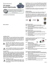
Certifications and Specifications
Wiring Diagram
Installation Notes
T-Series products can be used on both linear and rotary valve automation
applications. Always use sound mechanical practices when mounting. When
fastening the TopWorx™ switch box to the bracket on the actuator, torque the
fasteners to 224 in·oz (1.58 N·m) after cycling the valve a couple of times. This
allows the shaft to self-center in the pinion slot, or coupler. Be cautious not to
allow undue axial (thrust) load on the shaft.
This product comes shipped with conduit covers in an effort to protect
the internal components from debris during shipment and handling. It
is the responsibility of the receiving and/or installing personnel to
provide appropriate permanent sealing devices to prevent the intrusion
of debris, or moisture, when stored outdoors or when installed.
It is the responsibility of the installer, or end user, to install this prod-
uct in accordance with the National Electrical Code (NFPA 70 or any
other national or regional code defining proper practices.
Factory Preset
All TopWorx™ products are factory set for 90° rotation on normal acting actua-
tors. The switch at full clockwise is for process valve closed and uses the red
striker. When changing orientation the target disk will have to be relocated for
your application. The Target is designed to be adjusted on 90° increments
allowing the TopWorx™ unit to be rotated 90°, 180°, or 270° from standard. On
reverse acting units the switch function will be transposed. Clockwise for open
will become clockwise for closed. On units with indicator domes, the dome
cover with mask will have to be rotated to give proper indication.
Switch Calibration Procedure
Never perform the switch calibration procedure while in an area that
could be hazardous. Intrinsically Safe models, unit must be wired in
accordance the control drawing included with the product.
For Options Q, G, M, K, T, P, R, AS, DN & PB, calibration may be performed using a
Volt-Ohm meter by using the Ohm setting across COM and NO. When switch is
active, the meter will read <0.5 Ohms, or the Diode setting may be used simply to
indicate continuity. If a direct power source is being used, an appropriately sized
resistor must be used in series with the contacts, or permanent damage will occur.
For all INDUCTIVE sensor options, a power source and resistors will be required
for calibration. (Refer to the product nameplate for current limitations.)
Setting Switches
GO™ Switch, Mechanical Switches, Reed Switches, AS-i, DeviceNet, Profibus, &
ALL threaded, cylindrical inductive sensor options.
Each TV-Series unit is equipped with 2 or 4 adjustable targets with a usable range
between 45° and 90°. For normal acting applications the targets are color coded
red for closed and green for open (except the Q & G option). The color code would
be reversed for reverse acting units. After installing the unit on the actuator
or valve assembly, the targets must be set.
Normal Acting Actuator:
Step 1: Rotate the valve full clockwise
to the closed position.
Step 2: Unlock/push/twist the target as required to engage the switch and lock
target if applicable.
Step 3: Rotate the valve full counterclockwise to the open position.
Step 4: Unlock/ push/twist the target as required to engage the switch and lock
target if applicable.
Reverse Acting Actuator:
Step 1: Rotate the valve full clockwise to the open position.
Step 2: Unlock/push/twist the target as required to engage the switch and lock
target if applicable.
Step 3: Rotate the valve or push and move the target a full counterclockwise to the
closed position.
Step 4: Unlock/push/twist the target as required to engage the switch and lock
target if applicable
For switching angle under 45° (Not applicable for Q and G options.)
When the switch box is mounted to a linear actuator or when the actuator strokes
less than 45°, we recommend the following:
Step 1: Remove shaft from switch box by removing the circlip underneath the
switch box.
Step 2: Remove the circlip underneath the cam if equipped, then push the cam
down the shaft by 3-4mm and turn it 90°.
Step 3: Push the cam back up, you will see the flats fit snugly
between the locating lugs inside the hub.
Step 4: Replace the circlip
Step 5: Remove the closed switch from the bracket and install it on the inside of
the bracket next to the open switch
To re-assemble (Not applicable for Q and G options).
Step 1: Replace the screws with M3
X 25mm long screws (insert
through both switches and
bracket and fasten with the
nut on the inside closest to
the switch box bearing).
Step 2: Remove the Closed striker
assembly (red) by removing the circlip or screw on top, and install it on the
inner rack.
Step 3: Unlock target and twist the green striker to the other end of the cam’s rack
and lock target (The red striker assembly should be twisted to the other end
of the inner rack).
Step 4: Re-install the shaft in the switch box and fit the s/s washer and circlip to
the underside of the switchbox.
Step 5: The switches can now be set anywhere between 0°& 45°.
For switching angle up to 180° (Q/G-2 option only goes to 90°. Q/G-4 option can go
up to 180° if only 2 targets are utilized):
Step 1: Remove shaft from switch box by removing the circlip underneath the
switch box. Continued:
T-Series Models TVF, TVH
& TVL Quick Start Guide
OPEN
CLOSED


