Certifications and Specifications
Storage
Until conduit, conduit plugs, and any applicable spool valve port connections
are properly installed, the unit will not support its IP/NEMA rating as the unit
ships with temporary covers. Ensure that it is stored in a dry environment with a
relative humidity range between 10%-95% and a temperature ranging from -40ºF
(-40ºC) to 160ºF (71ºC). Once properly installed, the temperature range listed on
the nameplate will supersede this storage temperature range.
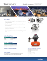
Installation Notes
TopWorx™ products can be used on both linear and rotary valve
automation applications. Always use sound mechanical practices
when mounting. When fastening the TopWorx™ switch box to the
bracket on the actuator, torque the fasteners to 8 ft·lbs (10.8 N·m)
after cycling the valve a couple of times. This allows the shaft to self
-center In the pinion slot, or coupler. Be cautious not to allow undue
axial (thrust) load on the shaft.
This product comes shipped with vinyl covers in an effort to protect
the internal components from debris during shipment and handling.
It is the responsibility of the receiving and/or installing personnel to
provide appropriate permanent sealing devices to prevent the intru-
sion of debris, or moisture, when stored outdoors or when installed.
It is the responsibility of the installer, or end user, to install this product in
accordance with the National Electrical Code (NFPA 70 or any other national or
regional code defining proper practices.
Factory Preset
All TopWorx™ products are factory set for 90º rotation, normal acting (CW to
close) with the standard conduit entries parallel to the process piping. Switch 1
(lower switch) is set to trip at full clockwise (closed) position of the process
valve. When changing orientation the target disk will have to be relocated for
your application. All U-Set Target disks are supplied with 4 slots on 90° incre-
ments allowing the TopWorx™ unit to be rotated 90°, 180°, or 270° from stand-
ard.
On reverse acting units the switch function will be transposed. On units with
indicator domes, the dome cover with mask will have to be rotated to give proper
indication.
For ESD units please download our Master IOM at: www.topworx.com/
manuals
Switch Calibration Procedure for Non-Bus Models
Applies to TopWorx D-Series with B, E, F, J, K, L, M, N, V, P, T, R, Z, 3, 7, 8, PS and
PN bus/sensor options (Refer to the fourth digit of the product part number to identify).
Never perform the switch calibration procedure while in an area that
could be hazardous. Intrinsically Safe models, unit must be wired in
accordance the control drawing included with the product.
For TopWorx D-Series with L, M, R, P, T, K and PN bus/sensor options: Calibra-
tion may be performed using a Volt-Ohm meter by using the Ohm setting across
COM and NO. When switch is active, the meter will read <0.5 Ohms, or the Diode
setting may be used simply to indicate continuity. If a direct power source is
being used, an appropriately sized resistor must be used in series with the con-
tacts, or permanent damage will occur. Refer to the certifications and specifica-
tions section for current limitations. For all other models a power source and
resistors will be required.
Depending on the model selected you will have one of two target designs. The
first uses a disk mounted to the shaft with moveable targets located in radial
slots. The second utilizes spring loaded cams which mate to splined shaft col-
lars allowing 360° adjustability. Some models, such as the DXP-ES, use a combi-
nation of both designs.
For U-Set Target builds with 1-4 switches:
Step 1: With the valve in the CLOSED position, loosen the target(s) (rotate
CCW) and slide the target(s) until the switch(es) activates. Tighten
the target(s) to 20 in-oz (rotate CW) to lock into position.
Step 2: With the valve in the OPEN position, loosen the target (s) until the
switches activates. Tighten the target(s) to 20 in-oz (rotate CW) to
lock into position.
Step 3: Cycle valve CLOSED and OPEN several times to ensure continued
calibration.
For splined shaft collar builds with 1-6 switches:
Step 1: With valve in the CLOSED position, disengage the cam(s) from the
splined hub(s) and rotate until the switch(es) activates. Release cam
(s) to re-engage splined hub(s).
Step 2: Rotate valve to OPEN position, disengage the cam(s) from the
splined hub(s) and rotate until the switch(es) activates.
Step 3: Cycle valve CLOSED and OPEN several times to insure continued
calibration
Calibration of 4-20mA Analog Position Transmitter
(optional)
The 4-20 current transmitter can be used for any rotation range between 20° and
320° and can be set to accommodate 3% over or under travel or for full linear.
Reverse directions are automatically accounted for during the calibration pro-
cess.
Step 1: Apply power to unit (LED should be continuously on)
Step 2: Option 1: +/- 3% Over and Under Travel at the Set End Points
Counter-clockwise calibration - Press the button greater than 0.5 sec-
onds and less than three seconds if you are going to calibrate using a counter-
clockwise rotation from the 4mA position to the 20mA position. (LED will start
flashing a 3 – 1 code indicating that calibration mode is active and the unit is
waiting to calibrate the 4mA position).
Clockwise calibration - Press the button greater than three seconds
and less than 5 seconds if you are going to calibrate using a clockwise rotation
from the 4mA position to the 20mA position. (LED will start flashing a 3 – 2 code
indicating that calibration mode is active and the unit is waiting to calibrate the
4mA position).
Option 2: No Under and Over Travel at Set End Points (Full
Linear)
Counter-clockwise calibration - Press the button greater than 5.5 sec-
onds and less than eight seconds if you are going to calibrate using a counter-
clockwise rotation from the 4mA position to the 20mA position. (LED will start
flashing a 5 - 1 code indicating that calibration mode is active and the unit is
waiting to calibrate the 4mA position).
Continued
D-Series Quick Start Guide
Wiring Diagram