Page is loading ...

1
2
3
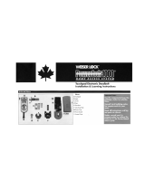
Begin with your smart home app
If you will be using a smart home app with your lock, download the app and set up
your controller or hub before proceeding further with lock installation.
1 / 4
66492001
Rev 02
914C
ZigBee
Installation and User Guide
ENGLISH
Kwikset Technical Support
1-866-863-6584
www.kwikset.com
Tools needed
Existing key
Phillips head screwdriver
Ruler
Optional: Masking tape
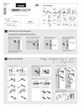
Prepare your door
Determine the parts needed for your door
Parts in the box
Kit "A" Kit "B" Kit "C"
Mounting
plate screws
Mounting
plate screws
Mounting
plate screws
Black mounting
plate
Interior
cover
Interior
assembly
Battery pack and
4 AA batteries
Silver mounting
plate
Gold mounting
plate
Black adapter
Gold adapter
Gold adapterBlack adapter
Silver adapter
Interior assembly
screws
Interior assembly
screws
Interior assembly
screws
Interior cover
screws
Interior cover
screws
Interior cover
screws
Make sure your existing deadbolt is compatible. If you have a standard deadbolt mounted
separately from the handle below it, it is compatible with Kwikset Convert.
Make sure your door is aligned before
proceeding with installation.
A B
Look into the hole in your door.
What shape is your torque blade (the part sticking out through the latch)?
For a list of compatible deadbolt
models, please see the Kwikset
Convert page at www.kwikset.com
Mortise
Lock
Not CompatibleNot Compatible
Rim
Lock
Integrated
Interior
Not CompatibleCompatible
D-shape
Kwikset and Weiser deadbolts:
Use kit “A” for your door.
Baldwin Reserve and
Baldwin Prestige deadbolts:
Use kit “B” for your door.
You will need the black adapter
and the thicker gold screws.
thicker
screws
Vertical rectangle
Baldwin Estate deadbolts:
Use kit “B” for your door.
You will need the gold adapter
and the thinner gold screws.
thinner
screws
Slanted rectangle
Schlage deadbolts:
Use kit “C” for your door.
You will need the silver adapter.
Horizontal rectangle
Schlage deadbolts:
Use kit “C” for your door.
You will need the gold adapter.
Make sure your door is open and
extend your latch bolt. Make sure your
key is NOT in the deadbolt exterior.
extended
Remove all existing deadbolt hardware
from the interior side of your door.
D
Optional: Secure your deadbolt
exterior with masking tape.
E
Measure to conirm that your door is either
13/8" or 13/4" (35 mm or 44 mm) thick.
13/8"or 13/4"
35 or 44 mm
C F
You should be able to lock and
unlock your door smoothly
without any resistance, and
without pushing, pulling
or lifting your door.
If your door is not aligned, you
may need to order a Warped
Door Service Kit, available
through Kwikset Support:
18668636584

2 / 4
4
Install the mounting plate and test your latch
torque blade
Note: A D-shaped torque blade is shown, but installation is the same for all models.
A
C D
Place the mounting plate on the door so that the torque
blade inserts through the center hole.
Kwikset & Weiser Only:
To determine which mounting
screws to use, test one of
the thicker screws irst.
If the thicker screw its, continue
installing the thicker screws.
If the thicker screw doesn't it,
install the thinner screws.
Remove the masking tape from the exterior deadbolt, and insert
your key and test the latch for smooth operation.
Remove your key and make sure the bolt is fully extended.
fully
extended
If the latch does not
extend or retract
smoothly, adjust the
mounting screws.
B
Keep parallel to the
edge of the door.
Tighten
screws evenly.
Secure the mounting plate with the mounting screws.
5
Install the interior assembly
D
Secure with two (2) interior assembly screws.
bottom
hole
Remove the interior cover and battery pack.
A
align tabs
Gold adapter:
Keep slot vertical.
Press adapter irmly onto
the interior assembly.
Install the adapter on the interior assembly.
back view
of interior
assembly
B
Silver adapter:
Tab is on bottom.
Black adapter:
Curve is on top.
a
b d
Make sure the
turnpiece is in the
vertical position.
Remove the
interior cover.
Remove the battery pack.
Do not
install
batteries
yet.
vertical
c
Make sure shaft is oriented
as shown. If needed, rotate
the shaft to this position.
Stripe should
be vertical.
C
Align the adapter with the torque blade and push the interior assembly
onto the mounting plate.
Schlage Deadbolts Only:
You may need to rotate
the adapter to align with
the torque blade.
actual
size

3 / 4
Pair the lock with your smart home system
window
If you wish to unlock
the window, you can
slide it up for more
convenient access
to the programming
buttons while the
cover is installed.
To unlock the
window, remove
the security screw.
The window
on the interior
cover is locked
by default to
prevent someone
from tampering
with your lock's
settings.
Important Information about the interior cover
Cover Installation:
Install cover.
Note: You may need to
rotate the turnpiece to align
with the turnpiece shaft.
turnpiece
shaft
Install screws.
a
b
Install the interior cover
Initiate the pairing process through
your smart home system (either
through your smart home app, at your
panel, or at your controller or hub).
Refer to your smart home system
instructions for more information.
When prompted by your smart home system
to initiate pairing at the lock, press button
“A” on the lock interior four times.
If successful, re-name the lock in your system (if applicable).
If unsuccessful, press button “B” nine times.
Perform steps 8A8C again.
If still unsuccessful, follow your smart home system's
instructions to remove (exclude/unpair) the lock from
any other network. Then perform steps 8A8C again.
A B C
D
button “A” button “B”
Note: The interior cover and
screws must be removed
for battery pack access.
actual
size
Conirm the lock status
Perform the door handing process
6
7
8
9
The Status LED blinks every six seconds to communicate
whether the door is locked or unlocked.
If the Status LED is displaying the
wrong lock status, lip switch #4.
A B
Amber:
Locked
Green:
Unlocked
Switch #4
This step will teach the lock the orientation of your door and is crucial for lock operation.
A B C D
Install 4 AA batteries
in the battery pack.
Ensure correct polarity.
For best results, use new,
non-rechargeable Alkaline
batteries only.
Make sure the door is open. Insert the battery pack
while PRESSING AND HOLDING the Program button.
Keep pressing the button for three seconds after the
battery pack is installed, then release the button.
The Status LED will lash red and
green, and the lock will beep.
Press and release the Program
button again.
The latch bolt will retract and extend on its own
to learn the orientation of the door. Did the
Status LED turn green or red?
If the bolt does not move, make sure
the batteries are installed correctly,
and perform steps 6A6D again.
status LED
Metal
contacts
at bottom,
facing out.
BALDWIN ESTATE DEADBOLTS:
If your latch bolt is to the RIGHT of your interior assembly, and the
Status LED is solid red after door handing, press and release the
Program button again. The door handing process will restart.
If you are unsure if your lock is Baldwin Estate, see
chart on page 1 or compatible deadbolt list online.
Red Status LED
Green: Door handing
successful. Continue
to step 7.
Red: See “Red Status
LED” below.
Right
OTHER DEADBOLTS:
If the Status LED is solid red after door handing, make sure
the batteries are installed correctly and the lock interior
is correctly installed. Perform steps 6A6D again.

4 / 4
© 2017 Spectrum Brands, Inc.
Reference Guide
Factory Reset
A factory reset will remove your lock from your smart home system.
Status
LED
1 Remove
battery
pack.
2 Press and HOLD the Program
button while reinserting
the battery pack.
Keep holding the button for 30
seconds until the lock beeps
and the status LED lashes red.
3 Press the Program
button once more.
When the LED lashes
green and you hear
two beeps, the lock
has been reset.
4 Perform the door handing
process again to teach the
lock the orientation of the
door and pair the lock to
your smarthome system.
1. Read all instructions in their entirety.
2. Familiarize yourself with all warning and caution statements.
3. Remind all family members of safety precautions.
4. Always have access to your lock’s standard key.
5. If using the Auto-Lock feature, make sure to have your
standard key with you to prevent locking yourself out.
6. Replace low batteries immediately.
CAUTION: Prevent unauthorized entry. Restrict access to your lock’s
back panel and routinely check your settings to ensure they have not
been altered without your knowledge.
WARNING: This Manufacturer advises that no lock can provide
complete security by itself. This lock may be defeated by forcible
or technical means, or evaded by entry elsewhere on the property.
No lock can substitute for caution, awareness of your environment,
and common sense. Builder’s hardware is available in multiple
performance grades to suit the application. In order to enhance
security and reduce risk, you should consult a qualiied locksmith or
other security professional.
Important Safeguards
Kwikset Convert at a Glance
AB
Button “A”
Back panel
Program button
Turnpiece shaft
Switches
Button “B”
Status LED
Switches
1. Status LED
Door lock status LED blinks every 6
seconds. ON position is factory default.
2. Auto-Lock
Automatically re-locks door 30
seconds after unlocking. OFF
position is factory default.
CAUTION: With this feature
enabled, it is possible to lock
yourself outside.
3. Audio
Beeping sound is heard during
programming and normal operation.
ON position is factory default.
4. Invert
Only used if the Status LED is
communicating the opposite
door lock status.
on o
1234
Status LED Notiications
Amber lash
Door is locked
Green lash
Door is unlocked.
Red lash
The 4 AA batteries
in the interior are
low and need to be
replaced.
Network Information
ZigBee System Notes
ZigBee is a “Wireless mesh network,” and results may vary
based on building construction and communication path,
with 35+ feet being typical installed distance in a standard
home environment and 250 feet+ when the lock has a clear
line of sight with the smart home controller or hub. It may be
necessary to install additional ZigBee devices to enhance the
communication path between the lock and controller/hub for a
more robust ZigBee network.
Removing the lock from the network
Press button “B” on the lock interior nine times.
These features can be adjusted
in some smart home apps.
/