
1 / 4
A
R or S
(2x)
A
A
B
B
B
U (2x)
T (2x)
D
Longer screws
install closest to
the door jamb.
door frame
Traditional Contemporary
A
B
68242001
Rev 01
ZWave Plus
Signature Series Deadbolt
with Home Connect
Installation and User Guide
Kwikset
1-866-863-6584
www.kwikset.com
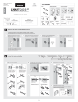
Parts in the box
Latch
“B” is not included. If needed,
please contact Kwikset to order
a drive-in latch for your lock.
Interior Assembly
Mounting
Plate
Fasteners
Exterior Assembly
If drilling a new door, use the supplied template and the complete
door drilling instructions available at www.kwikset.com/doorprep.
Note: Additional door preparation may be
required for doors with 11/2" (38 mm) holes.
Consult the deadbolt drilling instructions at
www.kwikset.com/doorprep.
*Service kits for 21/4" (57 mm) thick doors
are available through Kwikset.
or
backset
Measure to conirm that the hole in
the door is either 21/8" (54 mm) or
11/2" (38 mm).
Measure to conirm that the backset is
either 23/8" or 23/4" (60 or 70 mm).
23/8" or 23/4"
60 or 70 mm
13/8" – 13/4"*
35 – 44 mm*
Measure to conirm that the hole in
the door edge is 1" (25 mm).
Measure to conirm that the door is
between 13/8" and 13/4"* (35 mm
and 44 mm*) thick.
A
A B
C
D
E
B C D
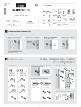
Is the door edge chiseled?
Are the latch holes centered in the door hole?
Which latch are you installing?
Install strike on the door frame.
Make sure the hole in the door frame is drilled a
minimum of 1" (25 mm) deep.
Hold the latch in front of the door hole, with the latch
face lush against the door edge.
21/8"
54 mm
11/2"
38 mm
1"
25 mm
YES
YES
NO
NO
Use latch “A”. If the
latch bolt is not already
extended, extend the
latch bolt as shown.
No adjustment is required.
Proceed to next step.
Rotate latch face as
shown to extend latch.
wood
block
Use latch “B” (not
included). If the latch
bolt is not already
extended, extend the
latch bolt as shown.
Latch “A” Latch “B”
ENGLISH
Required tools
Ruler
Hammer Wood block
Phillips head screwdriver
Additional Tools (depending on application)
Strike Cylinder
D
R
T
U
V
W
X
S
Keys SmartKey
tool
K
C
J
Batteries
Y
R
S
U
T
actual
size
A
B
E
F F
G G
H H
M
L
N
P
Q
Traditional Contemporary
or
chiseled
not
chiseled
or
or
1
Prepare the door and check dimensions
2
Install the latch and strike

2 / 4
Tighten screws evenly.
Install “L”
on exterior
assembly.
Do not
install “L.”
Install “P”
on exterior
assembly.
Install “P”
on exterior
assembly.
narrow
opening
wide
opening
a
b
c
21/8"
54 mm
11/2"
38 mm
Diameter is 21/8"
(54 mm)
Traditional Diameter is 11/2"
(38 mm)
Contemporary
oror
L
L
P P
M
N
C
J
V (2x)
V (2x)
E
E
Q
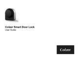
Insert key and
test latch. If latch
does not extend or
retract smoothly,
adjust screws (V).
Install exterior assembly and mounting plate.
C
Keep parallel to
edge of door.
Remove battery cover and battery pack from interior assembly. Install interior assembly onto mounting plate.
A B
a
c
b
d
If the turnpiece is pointing down (as
shown above), rotate the turnpiece
180° clockwise until you hear it click.
You may need to apply some force.
Make sure
turnpiece shaft is
rotated as shown.
Do not install
batteries
until step 5.
a
F
H
H
H
G
W
Remove key when
inished and make
sure the latch bolt
is fully extended.
W
(2x)
bottom
hole
b
If turnpiece shaft is not oriented
correctly, put the cover back on and
rotate the turnpiece as shown in step A.
What is the diameter of the hole in the door?
Install cylinder in exterior assembly.
A B
Traditional Traditional
Contemporary Contemporary
actual
size
V
actual
size
3
Install the exterior assembly and mounting plate
4
Install the interior assembly

Re-key the lock to work with your existing key. See the
supplied SmartKey Re-key instructions for more information.
Note: If Auto-Lock is enabled (see “Switches and Status LED
Colors”), remove the battery pack before re-keying your lock.
Optional: Re-key deadbolt (if needed)
8
K
3 / 4
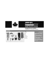
Add the lock to your smart home system
Initiate the process to add the
lock to your system at your
smart home controller.
Refer to your smart home
system instructions for
more information.
When prompted by your smart home system to add the
lock, press button “A” on the lock interior one time. The
red LED will illuminate when the lock enters Add Mode.
If successful, re-name the lock in your system (if applicable).
If unsuccessful, follow your system's instructions to remove
the lock from the controller and any other network, then press
button “A” on the lock one time.
Perform steps 6A6C again.
If still unsuccessful, consult the Programming and
Troubleshooting Guide, available on the “Deadbolt with
Home Connect” page at kwikset.com/wirelesslocks.
A B C
D
Please allow time for the controller to add the lock.
button “A”
actual
size
X (x3)
F
F
The window
on the interior
cover is locked
by default to
prevent someone
from tampering
with your lock's
settings.
Important Information about the interior cover
Cover Installation Battery Pack Access
Install cover.
Note: You may
need to rotate
the turnpiece to
align with the
turnpiece shaft.
turnpiece
turnpiece
shaft
Install
screws.
a
b
If the window is unlocked,
slide up the window to
access the battery pack.
If the window is locked,
remove the interior cover
and screws to access
the battery pack.
You can now slide
up the window for
more convenient
access to the
programming
buttons and the
battery pack
while the cover
is installed.
window
F
For easy
access to the
battery pack,
unlock the
window by
removing the
security screw.
inside view of
interior cover
X
Install the interior cover
Set locking and unlocking direction
5
6
7
Install 4 AA batteries in battery pack. Make sure the door is open. Press and hold the Program
button. Do not release.
Insert the battery pack and continue
holding the Program button.
A B C D
This step will teach your lock the orientation of your door and is crucial to lock operation.
G
Ensure correct polarity. For best results, use
new, non-rechargeable Alkaline batteries only.
Y
After 3 seconds, release
the Program button.
You will hear the lock beep and
the LED will lash red and green.
Press and release the
Program button again.
The latch bolt will retract and extend
on its own to learn the locking and
unlocking direction of the door.
E F G H
Status LED will
indicate success
or failure.
Success: LED
lashes green
Failure: LED
remains solid red
Note: Latch
bolt will
only retract
half way.
3s
Flashes
red and
green

4 / 4
Removing the lock from the network
Follow your smart home system’s instructions
to remove the lock from the network. When
prompted by the system, press button A” on the
lock interior once.
© 2018 Spectrum Brands, Inc.
1. Read all instructions in their entirety.
2. Familiarize yourself with all warning and caution statements.
3. Remind all family members of safety precautions.
4. Restrict access to your lock’s back panel and routinely check your settings to
ensure they have not been altered without your knowledge.
5. Dispose of used batteries according to local laws and regulations.
CAUTION: Prevent unauthorized entry. Restrict access to your lock's back panel and
routinely check your settings to ensure they have not been altered without your
knowledge.
WARNING: This Manufacturer advises that no lock can provide complete security
by itself. This lock may be defeated by forcible or technical means, or evaded by
entry elsewhere on the property. No lock can substitute for caution, awareness of
your environment, and common sense. Builder’s hardware is available in multiple
performance grades to suit the application. In order to enhance security and reduce
risk, you should consult a qualiied locksmith or other security professional.
Network Information Important Safeguards
ZWave System Notes
This product is a security enabled ZWave Plus product and must be used with a Security
Enabled ZWave controller to be fully utilized. ZWave is a “Wireless mesh network,” and
results may vary based on building construction and communication path.
To assure interoperability, each ZWave product must pass a stringent conformance test to
assure that it meets the ZWave standard for complete compliance with all other devices and
controls. The ZWave identity mark assures consumers, integrators, dealers and manufacturers
that their products will reliably perform with any other ZWave device. And, regardless of the
vendor, always powered nodes may act as a repeater for Kwikset/Weiser/Baldwin products.
ZWave Coniguration and Association Parameters are available on the Signature
Series Deadbolt with Home Connect (2nd Gen.) page at www.kwikset.com.
ZWave
Controller
12"
305 mm
ZWave
Controller
12"
305 mm
Deadbolt Interior at a Glance
Reference Guide
Status LED Notiications Factory Reset
Troubleshooting: Adding the Lock to a Smart Home System
A factory reset will remove the lock from your smart home system.
1 Remove battery pack. 2 Press and HOLD the
Program button while
reinserting the battery pack.
Keep holding the button
for 30 seconds until
the lock beeps and the
status LED lashes red.
3 Press the Program
button once more. When
the LED lashes green
and you hear two beeps,
the lock has been reset.
4 Perform the door handing process again to
teach the lock the orientation of the door, and
pair the lock with your smart home system.
Status
LED
Back panel
Some ZWave® systems require that the lock be within 12" of the controller during the adding process.
If this is the case, follow the steps below to remove the lock interior from the door to perform the process closer to the controller:
1 Remove the small screws that secure the interior assembly to the
mounting plate.
2 Remove the interior assembly from the door. 3 Hold the interior assembly a maximum of 12" (305 mm) from your
smart home controller for the rest of this process.
4 Initiate the process to add the lock to your system at your smart
home controller. Refer to your smart home system instructions for
more information.
5 When prompted by your smart home system to add the lock, press
button “A” on the lock interior one time. The red LED will illuminate
when the lock enters Add Mode.
6 Once successful, re-name the lock in your system (if applicable).
Then, reinstall the lock interior on the interior assembly.
Please allow time for the controller to add the lock.
These features can be adjusted in some smart home apps.
Switches
1. Status LED
Door lock status LED blinks every 6 seconds. ON position is factory default.
2. Auto-Lock
Automatically re-locks door 30 seconds after unlocking. OFF position is factory default.
CAUTION: With this feature
enabled, it is possible to lock
yourself outside.
3. Audio
Beeping sound is heard during programming and normal
operation. ON position is factory default.
4. Invert
Only used if the Status LED is communicating the opposite door lock status.
on o
1 2 3 4
Amber lash
Door is locked.
Green lash
Door is unlocked.
Red lash
The 4 AA batteries in the
interior are low and need
to be replaced.
Amber
LED
Green
LED
Red
LED
Program
button
Status
LED
Switches
Turnpiece
shaft
Note: When the cover is
removed, the turnpiece shaft
can be used to manually lock
and unlock the door.
Button “A” Button “B”
-
 1
1
-
 2
2
-
 3
3
-
 4
4


Kwikset 914S2TRLZW50011 User manual
- Type
- User manual
- This manual is also suitable for
Ask a question and I''ll find the answer in the document
Finding information in a document is now easier with AI
Related papers
-
Kwikset 914CNTZW500514S Installation guide
-
-
-
-
-
-
-
-
-
Other documents
-
 Weiser SmartCode 10 Touchpad Electronic Deadbolt GED1800 Z-Wave Plus User manual
-
 Weiser SmartCode 5 Touchscreen Electronic Deadbolt GED1495 Z-Wave User manual
-
 Weiser SmartCode 10 Touchscreen Electronic Deadbolt GED2150 Z-Wave User manual
-
 Premier Lock ML01R Installation guide
-
 COLZER SL-1 User manual
-
Baldwin 8212.412 Installation guide
-
 Weiser Lock Powerbolt 1000 Installation & Learning Instructions
-
 HuTools Door Lock Installation guide
-
Weiser Powerbolt 3 User guide
-
Weiser GED250 Installation guide


