Page is loading ...

M0R940E13-00 11/06/2013
Installation and
operating manual
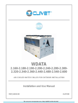
AIR COOLED INVERTER HEAT PUMP FOR OUTDOOR INSTALLATION
WSAN-XIN 21-141

Dear Customer,
We congratulate you on choosing these product
Clivet is being working for years to oer systems able to assure the maximum comfort for long time
with high reliability, eciency, quality and safety.
The target of the company is to oer advanced systems, that assure the best comfort, reduce the
energy con-sumption, the installation and maintenance costs for all the life-cycle of the system.
With this manual, we want to give you information that are useful in all the phases: from the
reception, to the installation and use until the disposal so that a system so advanced oers the best
procedure of installation and use.
Best regards and have a nice reading.
CLIVET Spa
The data contained in this manual is not binding and may be changed by the manufacturer without
prior notice.
Reproduction, even is part, is FORBIDDEN © Copyright - CLIVET S.p.A. - Feltre (BL) - Italia

M0R940E13-00 WSAN-XIN 21-141 3
Table of contents
1 Installation quick guide 5
2 General description 6
3 Reception 8
4 Positioning 10
5 Water connections 12
6 Electrical connections 15
7 Start-up 22
8 Control 27
9 Maintenance 41
10 Decommissioning 54
11 Residual risks 55
12 Dimensional drawings 56
13 Technical information 60
14 Accessories 64
15 Alarms - Stata 70

4 WSAN-XIN 21-141 M0R940E13-00

M0R940E13-00 WSAN-XIN 21-141 5
chapter / page
A Domestic hot water module 14.4 Boiler management→69
B Temperature probe domestic hot water 14.4 Boiler management→69
C Boiler 14.4 Boiler management→69
D 3-way DHW valve 14.4 Boiler management→69
E 3-way valve 14.4 Boiler management→69
F 1° setpoint control 14.4 Boiler management→69
G 2° setpoint control (2 setpoint>1 setpoint) 14.4 Boiler management→69
HBUS connection
H+H1 = 100mt max 14.4 Boiler management→69
I Control F delay respect to control E 14.4 Boiler management→69
L ON/OFF 6.7 SA1 = ON-OFF remote→20
M summer/winter 6.8 SA2 = Summer - Winter remote→20
N room thermostat 14.1 RCTX - Remote control→65
O Boiler control 6.6 Connections performer by customer→19
P Remote alarm signal 6.6 Connections performer by customer→19
Q Water lter 5.7 Water lter→14
R Bypass 14.4 Boiler management→69
S Power supply 6.4 Power input→15
Weight and dimensions 12 Dimensional drawings→56
1 Installation quick guide

6 WSAN-XIN 21-141 M0R940E13-00
2 General description
2.1 Manual
The manual provides correct unit installation, use and maintenance.
Pay particolar attention to:
Warning, identies particularly important operations or information.
Prohibited operations that must not be carried out, that compromise the operating of the unit or may cause damage to persons or things.
• It is advisable to read it carefully so you will save time during operations.
• Follow the written indications so you will not cause damages to things and injuries people.
2.2 Preliminaries
Only qualied personnel can operate on the unit, as required by the regulation in force.
2.3 Risk situations
The unit has been designed and created to prevent injures to people.
During designing it is not possible to plane and operate on all risk situation.
Read carefully “Residual risk” section where all situation which may cause damages to things and injuries to people are reported.
Installation, starting, maintenance and repair required specic knowledge; if they are carried out by inexperienced personnel, they may cause
damages to things and injuries people.
2.4 Intended use
Use the unit only:
• for cooling/heating water or a water and glycol mix for air-conditioning only
• attenendosi ai limiti previsti dal bollettino tecnico e dal presente manuale
Any use other than intended does not involve the manufacturer in any commitment or obligation.
2.5 Installation
The positioning, hydraulic system, refrigerating, electrics and the channelisation of the air must be determined by the system designer in
accordance with local regulations in force.
Follow local safety regulations.
Verify that the electrical line characteristics are in compliance with data quotes on the unit serial number label.
2.6 Maintenance
Plan periodic inspection and maintenance in order to avoid or reduce repairing costs.
Turn the machine o before any operation.
2.7 Modication
All unit modications will end the warranty coverage and the manufacturer responsibility.
2.8 Breakdown/Malfuction
Disable the unit immediately in case of breakdown or malfunction.
Contact a constructor certied assistance service.
Use original spares parts only.
Using the unit in case of breakdown or malfunction:
• voids the warranty
• may compromise the safety of the machine
• may increase time and repair costs

M0R940E13-00 WSAN-XIN 21-141 7
2.9 User training
The installer has to train the user on:
• Start-up/shutdown
• Set points change
• Standby mode
• Maintenance
• What to do / what not to do in case of breakdown
2.10 Data update
Continual product improvements may imply manual data changes.
Visit manufacturer web site www.clivet.it for updated data.
2.11 Indications for the user
Keep this manual with the wiring diagram in an accessible place for the operator.
Note the unit lable data so you can provide them at the assistance centre in case of intervention (see “Unit identication” section).
provide a machine notebook that allows any interventions carried out on the machine to be noted and tracked making it easier to suitably
note the various interventions and aids the search for any breakdowns.
In case of breakdown or malfunction:
• Immediately deactivate the unit
• Contact a assistance service centre authorized by the manifacturer
Ask the installer to format on:
• Start-up/shutdown
• Set points change
• Standby mode
• Maintenance
• What to do / what not to do in case of breakdown
2.12 Unit indentication
The serial number label is positioned on the unit and allows to indentify all the unit features.
It has not to be removed for any reason.
It reports the regulations indications such as:
• unit type
• serial number (12 characters)
• year of manufacture
• wiring diagram number
• electrical data
• manufacturer logo and address
2.13 Serial number
It identies uniquely each unit.
It identies specic spare parts for the unit.
2.14 Assistance request
Note data from the serial number label and write them in the chart on side, so you will nd them easily when needed.
Series
Size
Serial number
Year of manufacture
Electrical wiringdiagram

8 WSAN-XIN 21-141 M0R940E13-00
3 Reception
You have to check before accepting the delivery:
• That the unit hasn’t been damaged during transport
• That the materials delivered correspond with that indicated on the transport document comparing the data with the identication label
positioned on the packaging.
In case of damage or anomaly:
• Write down on the transport document the damage you found and quote this sentence: “Conditional acceptance clear evidence of
deciencies/damages during transport”
• Contest by fax and registered mail with advice of receipt to supplier and the carrier.
Any disputes must be made within the 8 days owing the delivery. Complaints after this period are invalid.
3.1 Storage
Observe external packaging instructions.
3.2 Handling
1. Verify unit weight and handling equipment lifting capacity.
2. Identify critical points during handling (disconnected routes, ights, steps, doors).
3. Use protections not to damage the unit.
4. Before starting the handling, make sure that the unit is stable.
5. Start hoisting the unit.
6. Remove screws

M0R940E13-00 WSAN-XIN 21-141 9
3.3 Packaging removing
Be careful not to damage the unit.
Keep packing material out of children’s reach it may be dangerous.
Recycling and disposing the packaging material in conformity with local regulations.

10 WSAN-XIN 21-141 M0R940E13-00
4 Positioning
During positioning consider these elements:
• Shafts required by the unit
• Electrical connections
• Water connections
• Spaces for air exhaust and intake
4.1 Functional spaces
Functional spaces are designed to:
• guarantee good unit operation
• carry out maintenance operations
• protect authorized operators and exposed people
Respect all functional spaces indicated in the DIMENSIONS section.
Double all functional spaces if two or more unit are aligned.
4.2 Positioning
Units are designed to be installed:
• EXTERNAL
• in xed positions
Limit vibration transmission:
• use antivibration devices on unit bearing points
• install exible joints on the hydraulic
Choose the installation place according to the following criteria:
• Customer approval
• safe accessible position
• technical spaces requested by the unit
• spaces for the air intake/exhaust
• avoid ood-prone places
• verify unit weight and bearing point capacity
• verify that all bearing points are aligned and leveled
• install the unit raised from the ground
• max. distance allowed by the electrical connections
• condensate water draining
Prefer places where the unit doesn’t disturb the neighbours.
Avoid installations next to bedrooms or windows.
Avoid snow accumulations on batteries.
A correct circulation of the air is indispensible to guarantee the good working order of the machine.
Avoid therefore:
• obstacles to the airow
• exchange diculties
• leaves or other foreign bodies that can obstruct the exchange batteries
• winds that hinder or favour the airow
• heat or pollution sources close to the unit (chimneys, extractors etc..)
• stratication (cold air that stagnates at the bottom)
• recirculation (expelled air that is sucked in again)
• positioning below the level of the threshold, close to very high walls, attics or in angles that could give rise to stratication or recirculation
phenomenons
Ignoring the previous indications could:
• energy eciency decrease
• blocks due to HIGH PRESSURE (in summer) or LOW PRESSURE (in winter)
A. Keep the min. distances from the podestrian areas.
B. Provide windbreaks in locations with strong winds.
C. Avoid snow accumulations on batteries.
D. Install the unit lifted from the ground.
E. Provide a protection.

M0R940E13-00 WSAN-XIN 21-141 11
4.3 Condensate water
When a heat pump is running it produces a considerable amount of water due to the defrosting cycles of the external coil.
The condensation must be eliminated in a manner to avoid wetting pedestrian areas.
The unit anti-freeze electric resistance prevents the ice from forming inside the tray.
With extensive very cold outdoor temperatures, condensation could freeze outside the unit blocking the ow and causing a slow build-up of
ice; therefore special attention must be paid to eliminating condensation, raising the unit o the ground and evaluating whether antifreeze
elements should be installed.
A. Condensation collection basin
B. Unit support
C. Condensate discharge connection Ø 13

12 WSAN-XIN 21-141 M0R940E13-00
5 Water connections
5.1 Water quality
The water quality can be checked by qualied personnel.
Water with inadequate characteristics can cause:
• pressure drop increase
• energy eciency decrease
• corrosive symptom increase
Acceptable water quality values:
Provide a water treatment system if values fall outside the limits.
5.2 Risk of freeze
If the unit or the relative water connections are subject to temperatures close to 0°C:
• mix water with glycol, or
• safeguard the pipes with heating cables placed under the insulation, or
• empty the system in cases of long non-use
5.3 Anti-freeze solution
Consider that the use of anti-freeze solution determines an increase in a pressure drop.
Make sure that the glycol type utilized is inhibited (not corrosive) and compatible with the hydraulic circuit components.
Do not use dierent glicol mixture (i.e. ethylic with propylene).
5.4 Water ow-rate
The project water-ow must be:
• inside the exchanger operating limits (see the TECHNICAL INFORMATION section)
• guarantee, also with variable system conditions (for example in systems where some circuits are bypassed in particular situations).
5.5 Operation sequence
1. Carefully wash the system with clean water: ll and drain the system several times.
2. Apply additives to prevent corrosion, fouling, formation of mud and algae.
3. Fill the plant
4. Execute leakage test.
5. Isolate the pipes to avoid heat dispersions and formation of condensate.
6. Leave various point of service free (wells, vent-holes etc).
Neglecting the washing will lead to several lter cleaning interventions and at worst cases can cause damages to the exchangers and the
other parts.

M0R940E13-00 WSAN-XIN 21-141 13
5.6 Racommended connection
The installer must to dened:
• component type
• position on system
1 Pump / circulating pump 9 lling valve
2vent 10 shut-o valve
3 limit unit 11 Internal storage tank
4 antivibration joints 12 lter
5 piping support 13 Flow Switch
6 expansion vessel 14 safety valve
7 pressure gauge 15 Drain valve
8 thermometer 16 utility side exchanger
(sizes 21÷71)
A. vent
B. pump
C. input probe
D. Safety valve (6 Bar)
E. plate exchanger
F. Flow Switch
G. input probe
H. water outlet

14 WSAN-XIN 21-141 M0R940E13-00
(size 81÷141)
A. vent
B. Dierential pressure switch
C. input probe
D. plate exchanger
E. pump
F. input probe
G. Safety valve (6 Bar)
H. water outlet
5.7 Water lter
If not present on-board the machine, must be installed immediately in the water input of the unit, in a position that is easily accessible for
cleaning.
The lter never should be removed, this operation invalidates the guaranty.

M0R940E13-00 WSAN-XIN 21-141 15
6 Electrical connections
The characteristics of the electrical lines must be determined by specialized personnel able to design electrical installations; moreover, the
lines must be in conformity with regulations in force.
The protection devices of the unit power line must be able to stop the presumed short circuit current, whose value must be determined in
function of system features.
The power cables and the protection cable section must be dened in accordance with the characteristics of the protections adopted.
All electrical operations should be performed by trained personnel having the necessary requirements by the regulations in force and being
informed about the risks relevant to these activities.
Operate in compliance with safety regulations in force.
6.1 Electrical data
The serial number label reports the unit specic electrical data, included any electrical accessories.
The electrical data indicated in the technical bulletin and in the manual refer to the standard unit, accessories excluded.
It reports the regulations indications such as:
• Voltage
• F.L.A.: full load ampere, absorbed current at maximum admitted conditions
• F.L.I.: full load input, full load power input at max. admissible condition
• Electrical wiringdiagram Nr.
If the DHW module is present, consider the electric resistance absorption in the power supply line dimensionino.
6.2 Connections
1. Refer to the unit electrical diagram (the number of the diagram is shown on the serial number label).
2. Verify that the network has characteristics conforming to the data shown on the serial number label.
3. Before starting work, verify that the sectioning device at the start of the unit power line is open, blocked and equipped with cartel
warning.
4. Primarily you have to realize the earthing connection.
5. Shelter the cables using adequate measure fairleads.
6. Before power the unit, make sure that all the protections that were removed during the electrical connection work have been restored.
6.3 Signals / data lines
Do not overpass the maximum power allowed, which varies, according to the type of signal.
Lay the cables far from power cables or cables having a dierent tension and that are able to emit electromagnetic disturbances.
Do not lay the cable near devices which can generate electromagnetic interferences.
Do not lay the cables parallel to other cables, cable crossings are possible, only if laid at 90°.
Connect the screen to the ground, only if there aren’t disturbances.
Guarantee the continuity of the screen during the entire extension of the cable.
Respect impendency, capacity and attenuation indications.

16 WSAN-XIN 21-141 M0R940E13-00
6.4 Power input
A, B: Ø 22 mm
C: Ø 34 mm
Install the isolator switch near the unit.
Fix the cables: if vacated may be subject to tearing.
The cable don’t have to touch the compressor and the refrigerant piping (they reach high temparatures).

M0R940E13-00 WSAN-XIN 21-141 17
6.5 Electrical panel
ASignals BRS485 CPower supply
AP1 Main control module FU1 Fuse
AP2 Electronic thermostatic management FU2 230V aux. cicuit fuse
AP4 Fan control module KA1 Inverter alarm auxiliary relay
AP6 RS 485 module
(OPTIONAL)
KA2 Compressor control relay
C1
C2
Fan capacitor KA3 Ciculation pump control relay
T1 Transformer XT1 Terminal block of the customer connections

18 WSAN-XIN 21-141 M0R940E13-00
ASignals BRS485 CPower supply
AP1 Main control module FU1 230V aux. cicuit fuse
AP2 Electronic thermostatic management FU2 compressor overload protection and timer
AP4 Fan control module QS1 Main isolator switch
AP6 RS 485 module
(OPTIONAL)
QM1 Compressor line protection
C1
C2
Fan capacitor KA1 Inverter alarm auxiliary relay
T1 Transformer KA2 Compressor control relay
FU1 compressor overload protection and timer
Size 51-71
KA3 Ciculation pump control relay
FU2 230V aux. cicuit fuse
Size 51-71
XT1 Terminal block of the customer connections

M0R940E13-00 WSAN-XIN 21-141 19
6.6 Connections performer by customer
Electrical panel
(sizes 21÷71)
1 Unit QG Electrical panel
2 Connections perfomer by customer AP7 Room keypad
3 Only for sizes 21-41 SA2 Remote summer/winter
6.8 SA2 = Summer - Winter remote→20
4 Only for sizes 51-71 SA1 Remote ON-OFF
6.7 SA1 = ON-OFF remote→20
A Fuses
Provided by the customer
M8 Pump use
Provided by the customer
B Isolating switch
Provided by the customer
XT1 Terminal block of the customer connections
FU1 Fuse

20 WSAN-XIN 21-141 M0R940E13-00
Electrical panel
(size 81÷141)
1 Unit SA1 Remote ON-OFF
2 Connections perfomer by customer SA2 Remote summer/winter
A Fuses
Provided by the customer
AP7 Room keypad
QS1 Isolating switch M8 Pump use
Provided by the customer
QG Electrical panel XT1 Terminal block of the customer connections
6.7 SA1 = ON-OFF remote
Set parameter CL43 as shown in the table
CL43 ON/OFF Standby Time bands only DHW
-2 SA1 = ON-OFF remote from menu YES from menu
-1 ON/OFF only by keypad SA1 = remote standby NO from menu
0ON/OFF only by keypad
(SA1 disabled)
Menu standby
(SA1 disabled) YES from menu
28 from keypad from menu YES SA1 = only Domestic Hot Water
remote
OFF: emergency stop, not active the antifreeze safeties etc.
Standby: assisted stop, are active the antifreeze safeties etc.
6.8 SA2 = Summer - Winter remote
Set parameter CL44
CL44 Summer/Winter change
0 from keypad SA2 = disabled
-3 by SA2 change from keyboard disabled
SUMMER
WINTER
6.9 Remote control with room thermostat
For details see: 14.1 RCTX - Remote control→65
6.10 Domestic hot water module
For details see: 14.3 AMACSX - Domestic hot water module→67
6.11 Serial communication module with RS485 serial converter kit
For details see: 14.2 CMSC2X - Serial communication module with RS485 serial converter kit→66
/