Page is loading ...

Installation use and maintenance manual
WSH-XSC 65D - 180F
WATER COOLED CHILLERS OF 195 TO 560 kW
M03Y40D9-04 15-10-2012

2
Dear Customer,
We congratulate you on choosing these product.
Clivet is being working for years to offer systems able to assure the maximum
comfort for long time with high reliability, efficiency , quality and safety. The
target of the company is to offer advanced systems, that assure the best com-
fort, reduce the energy con-sumption, the installation and maintenance costs
for all the life-cycle of the system.
With this manual, we want to give you information that are useful in all the
phases: from the reception, to the installation and use until the disposal so
that a system so advanced offers the best procedure of installation and use.
Best regards and have a nice reading !
CLIVET Spa

3
1
2
3
4
General 4
Reception 6
Positioning 7
Water connections 8
Electrical connections 13
Start-up 19
Regulation 24
Maintenance 29
Disposal 32
Residual risks 33
Technical information 35
5
6
7
8
9
10
11
INDEX

4
1.2 GENERAL INSTRUCTIONS
Preliminaries
The positioning, hydraulic system, refrigerating, electrics and
the channelisation of the air must be determined by the
system designer in accordance with local regulations in force.
Only qualified personnel can operate on the unit, as required
by the regulation in force.
Using the unit in case of breakdown or malfunction :
• voids the warranty
• may compromise the safety of the machine
• may increase time and repair costs.
Follow local safety regulations. .
Keep packing material out of children’s reach it may be
dangerous. .
Recycle and dispose of packing material in conformity with
local regulations. .
Risk situations
The unit has been designed and created to prevent injures to
people.
During designing it is not possible to plane and operate on all
risk situation.
Read carefully "Residual risk" section where all situation
which may cause damages to things and injuries to people
are reported.
Installation, starting, maintenance and repair required specific
knowledge; if they are carried out by inexperienced personnel,
they may cause damages to things and injuries people.
Intended use
Use the unit for cooling/heating water or a water and glycol
mix for air-conditioning only, within limits defined in the
technical bulletin and on this manual..
Any use other than intended does not involve the
manufacturer in any commitment or obligation. .
Installation
Verify that the electrical line characteristics are in compliance
with data quotes on the unit serial number label.
Maitenance
Plan periodic inspection and maintenance in order to avoid or
reduce repairing costs.
Turn the machine off before any operation.
Modification
All unit modifications will end the warranty coverage and the
manufacturer responsibility. .
Breakdown/Malfuction
Disable the unit immediately in case of breakdown or
malfunction. .
Contact a constructor certified assistance service.
Use original spares parts only.
User training
The installer has to train the user on :
• start-up / shutdown;
• set points change;
• standby mode;
• maintenance;
• what to do / what not to do in case of breakdown.
Data update
Continual product improvements may imply manual data
changes .
Visit manufacturer web site for updated data.
Keep this manual with the wiring diagram in an accessible
place for the operator.
Note the unit lable data so you can provide them at the assi-
stance centre in case of intervention (see "Unit identification"
section).
Provide a machine notebook that allows any interventions
carried out on the machine to be noted and tracked making it
easier to suitably note the various interventions and aids the
search for any breakdowns.
In case of breakdown or malfunction:
• immediately deactivate the unit .
• contact a assistance service centre authorized by the
manifacturer.
• use original spares parts only
Ask the installer to format on:
• start-up / shutdown;
• set points change;
• standby mode;
• maintenance;
• what to do / what not to do in case of breakdown.
1.3 INDICATIONS FOR THE USER
The manual provides correct unit installation, use and
maintenance.
Pay particolar attention to:
Warning identifies particularly important operations or
information .
Prohibited operations that must not be carried out, that
compromise the operating of the equipment or may cause
damage to persons or things.
• It is advisable to read it carefully so you will save time
during operations.
• Follow the written indications so you will not cause
damages to things and injuries people. The preliminary
information must be read prior to carrying out any of the
following operations.
1.1 MANUAL
1 - GENERAL

5
1 - GENERAL
1.4 UNIT INDENTIFICATION
Serial number label
The serial number label is positioned on the unit and allows to
indentify all the unit features.
It has not to be removed for any reason.
It reports the regulations indications such as:
• machine type, exmple:
Series WSH-XSC
Size 65D...
• serial number
12 characters Axxxxxxxxxxx
• year of manufacture
• wiring diagram number
• electrical data
• manufacturer logo and address .
Serial number
It identifies uniquely each machine.
It identifies specific spare parts for the machine.
Assistance request
Note data from the serial number label and write them in the
chart on side, so you will find them easily when needed.
In case of intervention you have to provide data.
Serie
Size
Serial number
Year of manufacture
Wiring diagram
Size PE code W1 W2 W3 W4
65D PE960003 C6100024 C6100024 C6100024 C6100024
70D PE960003 C6100024 C6100024 C6100024 C6100024
75D PE960003 C6100024 C6100024 C6100024 C6100024
80D PE980002 C6100024 C6100026 C6100024 C6100026
85D PE980002 C6100024 C6100026 C6100024 C6100026
90D PE980002 C6100024 C6100026 C6100024 C6100026
100D PE980002 C6100024 C6100026 C6100024 C6100026
110D PE980002 C6100024 C6100026 C6100024 C6100026
115D PE980002 C6100024 C6100026 C6100024 C6100026
120D PE980002 C6100024 C6100026 C6100024 C6100026
135E PE960004 C6100026 C6100026 C6100026 C6100026
150F PE960004 C6100026 C6100026 C6100026 C6100026
165F PE980005 C6100026 C6100026 C6100028 C6100028
180F PE980005 C6100026 C6100026 C6100028 C6100028
ANTIVIBRATION DEVICES
It is recommended to put the unit on specific antivibration
devices .
Each support point of the unit sustains a different weight.
Therefore, each anti-vibration device is sized for a specific support
point, and can only be placed there.
The anti-vibration devices must therefore be placed in accordance
with the instructions provided with them and with the dimensional
drawings in which the support points are indicated by W1 , W2 ,
W3 etc .
On each anti-vibration device (if provided by CLIVET), its
identifying code is stamped, for example C6100100
Flexible joints are necessary on all the hydraulic/ aeraulic
connections (the joints are not supplied by Clivet)

6
2 - RECEPTION
Operate in compliance with safety regulations in force .
For detailed information (dimensions, weight, technical
characteristics etc.) please refer to the TECHNICAL
INFORMATION section.
Use single protection devices : gloves, glasses etc
2.1 PRELIMINARY INFORMATION
2.2 DELIVERY CONTROL
2.4 HANDLING
Check the position of the centre of gravity in the TECHNICAL
INFORMATIONS—DIMENSIONS section.
Use protections not to damage the unit.
Observe external packaging instructions .
Be careful not to damage the unit.
Recycling and disposing the packaging material in
conformity with local regulations.
2.3 STORING
Verify unit weight and handling equipment lifting
capacity .
Identify critical points during handling (disconnected routes,
flights, steps, doors).
Check the position of the centre of gravity in the TECHNICAL
INFORMATIONS—DIMENSIONS section.
Before starting the handling, make sure that the unit is stable.
2.5 PACKAGING REMOVING
Lifting beam with spacers
Before accepting the delivery you have to check:
• that the unit hasn’t been damaged during
transport
• that the materials delivered correspond with that
indicated on the transport document comparing the
data with the identification label positioned on the
packaging.
In case of damage or anomaly:
• write down on the transport document the
damage you found and quote this sentence:
"Conditional acceptance — clear evidence of
deficiencies/damages during transport".
• Contest by fax and registered mail with advice of
receipt to supplier and the carrier.
Any disputes must be made within the 8 days owing the
delivery. Complaints after this period are invalid.
A
A
B

7
3 - POSITIONING
Operate in compliance with safety regulations in force.
For detailed information (dimensions, weight, technical
characteristics etc.) please refer to the TECHNICAL
INFORMATION section.
Use single protection devices : gloves, glasses etc.
During positioning consider these elements :
• technical spaces requested by the unit and the system
• choice of the unit installation place
• electrical connections
• water connections
3.1 PRELIMINARY INFORMATION
3.4 FRESH AIR PROBE
The external probe allows to automatically change the unit set
point according to the external enthalpy (temperature +
humidity).
It is then possible to optimize the unit energy efficiency.
A
B
C
NORD
3.2 FUNCTIONAL CLEARANCES
3.3 POSITIONING
The functional clearances have to :
• guarantee the unit good operating
• allow the maintenance operations
• safeguard the authorized operators and the exposed
person
Respect the functional clearances indicated in the
TECHNICAL INFORMATION - DIMENSIONS section.
Double the functional clearances if more units are aligned.
The unit has been designed to be installed :
• INDOOR
• in fixed position
• in premises with Max ambient temperature= 40 °C
(49 °C with “electrical panel ventilation” option)
• in premises with Max ambient RH = 50% at 40 °C
Limit the vibration transmission:
• use vibration isolators on the unit support points
• install the flexible joints on the water connections.
Installation criteria:
• safe accessible position
• avoid flood-prone places;
• verify the unit weight and bearing point capacity;
• verify that all bearing points are aligned and levelled
• install the unit raised from the ground
SAFETY VALVE GAS SIDE
The installer is responsible for evaluating the opportunity of
installing drain tubes, in conformity with the local regulations in
force ( EN 378 )
POSITIONING
The sensor should not be influenced by factors that can
distort the reading (eg direct sunlight, air exhausted from the
fan or other sources, contact with the unit structure or other
heat sources, accumulations of snow / ice).
Examples to position the external probe :
• A roof
• B under a terrace
• C if at free wall provide a small roofing

8
4 - WATER CONNECTIONS
4.1 PRELIMINARY INFORMATION
4.3 OPERATION SEQUENCE
4.4 WATER QUALITY
The water quality is determined by the following factors, avoid
therefore:
• Inorganic salts
• pH
• Biological load (seaweeds etc)
• Suspended solids
• Dissolved oxygen
Water with inadequate characteristics can cause:
• pressure drop increase
• energy efficiency decrease
• corrosive symptom increase
4.5 RISK OF FREEZE
4.6 ANTI-FREEZE SOLUTION
Consider that the use of anti-freeze solution determines an
increase in a pressure drop.
Make sure that the glycol type utilized is inhibited (not corrosi-
ve) and compatible with the hydraulic circuit components
(pump etc).
Do not use different glicol mixture (i.e. ethylic with propylene)
Selection and installation of system components must be
carry out by installer.
Following you will find some indications to integrate with what
is provided by the local regulations in force and by the good
technical laws.
4.2 COMPONENTS
4.7 VICTAULIC CONNECTIONS
• Take away the supplied connection union by acting on the
connection joint Victaulic.
• Weld the union to the installation pipe.
• Perform the connection between the installation pipe and
the evaporator, using the joint.
Do not weld the system pipe with the Victaulic connection joint
attached.
The rubber gasket might be irreparably damaged.
CUT-OFF VALVES :
• installed at inlet and outlet (both on the water technique
circuit as well as that of the hot domestic water) allow
maintenance operations without having to empty the
system .
THERMOMETERS AND MANOMETERS :
• installed at entry and exit of the main elements facilitate
inspection and maintenance.
AN AIR BLEED VALVE :
• installed in all of the highest points of the system allowing
the venting of the circuits air..
DRAINAGE TAPS :
• installed in the lowest points of the system to allow
bleeding.
EXPANSION TANK :
• It keeps a correct system pressure when the water
temperature changes.
It must be dimensioned as a function of water content.
WATER FILTER :
• if not present on-board the machine, must be installed
immediately in the water input of the unit, in a position that
is easily accessible for cleaning.
• Mesh dimension: 1,0 mm2 unit with 1 compressor
• Mesh dimension: 1,5 mm2 multicompressor unit
• The filter never should be removed, this operation
invalidates the guaranty
SUPPORTS :
• The hydraulic pipes weight mustn’t burden on the unit
connections ..
FLOW SWITCH
• The flow switch must be present as a component of the
system
If the unit or the relative water connections can be subject to
temperatures close to 0°C adopt measures for prevent risk of
freeze.
For example:
• Mix water with ethylene glycol
• Safeguard the pipes with heating cables placed under the
insulation
• Empty the system in cases of long non-use and check that:
• there are no closed taps present that could trap water
even after emptying
• there are no low points in which water can stagnate
even after emptying; carry out any blowing required .
1. Execute leakage test
2. Carefully wash the system by filling it and emptying it
several times with clean water.
Ignoring this operation will lead to several filter cleaning
interventions and at worst cases can cause damages to
the exchangers and the other parts.
3. Prepare anti-freeze solution if required
4. Fill the plant
5. vent the plant
6. Isolate the pipes to avoid heat dispersions and formation
of condensate isolate all the pipes.
Leave various point of service free (wells, vent-holes etc ).

9
4 - WATER CONNECTIONS

10
WATER CONNECTIONS
ONLY COOLING
Standard: OCO
1. EVAPORATOR - cool side
use side connections
2. CONDENSER - heat side
source side connections
HEAT PUMP
Option: OHP
SUMMER
1. EVAPORATOR - cool side
use side connections
2. CONDENSER - heat side
source side connections
WINTER
1. CONDENSER - heat side
use side connections
2. EVAPORATOR - cool side
source side connections
REVERSAL ON WATER CIRCUIT
Option: OHI
SUMMER
1. EVAPORATOR - cool side
2. CONDENSER - heat side
EVAPORATOR water temperature control
WINTER
1. EVAPORATOR - cool side
2. CONDENSER - heat side
CONDENSER water temperature control

11
WATER CONNECTIONS
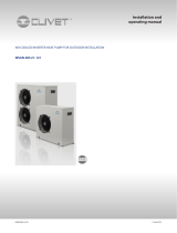
HYDROPACK - OPTIONAL
The equipment of refrigerant groups with the Hydropack
accessory allows the supply of the necessary rate/head with
different solutions:
HYDROPACK with 1 pump
for low-power units you can choose the basic solution with 1
pump.
HYDROPACK with 1 pump + 1 standby
also for low-power units you can include a second pump for
complete reliability. If one pump shuts down, the other one
automatically starts up and the unit control signals the
shutdown of the pump that is out of order. The micro-
processor automatically balances the hours of operation of
both pumps
HYDROPACK with 2 pumps
Per less power units, the standard solution with 2 pumps can
be chosen. If a pump gets blocked, the unit will go on working
till about 80% of the charge. This solution is more reliable than
the traditional ones with a single great power pump.
HYDROPACK with 2 pumps + 1 stand-by,
2 reserve pump can be foreseen for assuring a total reliability.
So the design water rate is assured (in fact, in the event of a
failure, the reserve pump is automatically activated and the
unit control signals if the broken pump is blocked).
HYDROPACK with 3 pumps
for units of greater power; with the solution of 3 pumps which
are always activated, the possible blocking of a pump always
assures the regular working up to 80% of the charge (always
with the signalization of the blocking). In this case, it is
possible, upon request, to supply a reserve pump (not
connected). The replacement is performed in few minutes
time, thanks to the simple foreseen connections.
The modular pumping system allows for the automatic
reduction of the water rate, in case the temperature is above
the operating limit.
This device is very useful during starts-up, weekend pauses,
and after a long period of inactivity.
When the water temperature of the hydronic circuit is very
high, possible blocks for overcharging are avoided, as well as
the consequent interventions of specialized personnel for the
assisted start-up.
OPTIONAL
VS
VR
P
PRS
R
M
M
PHE
R
FR
Multi pump hydronic group including:
R = shut-off valves
F = steel mesh filter(optional)
M = manometers
VS = safety valve (6 Bar)
P = high efficiency single-structure and single-rotor electric
pumps
VR = check valves
PRS = safety pressure switch (avoids pumps operation in
case of water absence)
PHE = evaporator-kit including two blind plugs needed in case
of pump removal for maintenance operations

12
WATER CONNECTIONS

13
5 - ELECTRICAL CONNECTIONS
5.1 PRELIMINARY INFORMATION
5.5 ELECTRIC LINES INLET
F.L.A. full load ampere
Full load current at max admissible conditions
F.L.I. Full load input
Full load power input
( at max. admissible condition )
serial
number
label VOLTAGE
FLA (A)
FLI (kW)
The serial number label reports the unit specific electrical
data, included any electrical accessories .
The electrical data indicated in the technical bulletin and in the
manual refer to the standard unit, accessories excluded.
Refer to the electrical data report on the serial number label.
5.2 ELECTRICAL DATA
5.3 CONNECTIONS
1. refer to the unit electrical diagram (the number of the
diagram is shown on the serial number label)
2. verify that the network has characteristics conforming to
the data shown on the serial number label
3. Before starting work, verify that the sectioning device at
the start of the unit power line is open, blocked and
equipped with cartel warning
4. Primarily you have to realize the earthing connection
5. Shelter the cables using adequate measure fairleads
6. Before power the unit, make sure that all the protections
that were removed during the electrical connection work
have been restored.
5.4 SIGNALS / DATA LINES
Do not overpass the maximum power allowed, which varies,
according to the type of signal.
Lay the cables far from power cables or cables having a
different tension and that are able to emit electromagnetic
disturbances.
Do not lay the cable near devices which can generate
electromagnetic interferences.
Do not lay the cables parallel to other cables; cable crossings
are possible, only if laid at 90°.
Connect the screen to the ground, only if there aren’t
disturbances
Guarantee the continuity of the screen during the entire
extension of the cable.
Respect impendency, capacity and attenuation indications.
Fix the cables: if vacated may be subject to tearing.
The cable don't have to touch the compressor and the
refrigerant piping ( they reach high temparatures ).
The characteristics of the electrical lines must be determined
by specialized personnel able to design electrical installations;
moreover, the lines must be in conformity with regulations in
force.
The protection devices of the unit power line must be able to
stop the presumed short circuit current, whose value must be
determined in function of system features.
The power cables and the protection cable section must be
defined in accordance with the characteristics of the
protections adopted. All electrical operations should be
performed by trained personnel having the necessary
requirements by the regulations in force and being informed
about the risks relevant to these activities.
Operate in compliance with safety regulations in force .

14
5 - ELECTRICAL CONNECTIONS
5.6 CONNECTIONS PERFORMER BY CUSTOMER

15
5 - ELECTRICAL CONNECTIONS

16
5 - ELECTRICAL CONNECTIONS

17
5 - ELECTRICAL CONNECTIONS
AP18 demand-limit
AP19 water reset
AP20 Ambient humidity control probe
XC Terminal block of Customer connections a Devices powered by the signal
b Devices with own power supply
c Passive devices powered by the module (max 50mA)
5.7 DEMAND LIMIT and WATER RESET
a
b
c

18
5 - ELECTRICAL CONNECTIONS
AP10 Gateway Modbus RS485
AP12 Remote interface terminal
AP13 Remote interface
AP14 Gateway LonWorks
APBK Gateway Bacnet
XC Terminal block of Customer connections
5.8 COMUNICATION
Cable "A" requirements:
Couple of conductors twisted and shielded
Section of conductor 0.22mm2…0,35mm2
Nominal capacity between conductors < 50 pF/m
nominal impedance 120 Ω
Recommended cable BELDEN 3105A
A
A
A
A
A

19
6 - START-UP
PRELIMINARY CHECKS
To check before starting-up the unit .
For details refer to the different manual sections.
√ Preliminary checks - Unit OFF power supply
Access in safety
Functional clearances
Structure integrity
Unit on vibration isolators
Unit input water filter + shut-off valves for cleaning
Vibration isolators on water connections
Expansion tank (indicative volume = 5% system content)
Cleaned system
Loaded system + possibile glicole solution + corrosion inhibitor
Under pressure system
Vented system
Refrigerant circuit visual check
Earthing connection
Power supply features
Electrical connections provided by the customer
Outside air temperature probe

20
6 - START-UP
START-UP SEQUENCE
√ Start-up sequence - Unit ON power supply
Compressor carter resistances operating at least since 8 hours
Off-load voltage measure
Phase sequence check
Pump manual start-up and flow check
Unit ON
Load voltage measure and absorptions
Liquid light check (no bubbles)
Measure of return and supply water temperature
Super-heating and sub-cooling measure
Check no anomalous vibrations are present
Set-point personalization
Climatic curve personalization
Complete and available unit documentation
Operations to perform to start-up the unit.
For details refer to the different manual sections.
/