CLIVET WSAN-XEE Series Installation and Use Manual
- Category
- Split-system air conditioners
- Type
- Installation and Use Manual


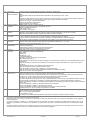
UNIT IDENTIFICATION........................................................................... 4
INSTRUCTIONS FOR THE USER............................................................... 5
COMMON CAUSES OF SHUTDOWN ...........................................................................................................................7
GENERAL WARNINGS............................................................................ 8
RESIDUAL RISKS ................................................................................. 9
RECEPTION........................................................................................12
INSPECTION UPON RECEPTION...............................................................................................................................12
STORAGE ....................................................................................................................................................................12
HANDLING ...................................................................................................................................................................12
POSITIONING .....................................................................................13
GENERAL.....................................................................................................................................................................13
FUNCTIONAL CLEARANCES......................................................................................................................................13
POSITIONING ..............................................................................................................................................................13
WATER CONNECTIONS .........................................................................15
GENERAL.....................................................................................................................................................................15
EXCHANGER USE SIDE .............................................................................................................................................15
DIAGRAM OF RECOMMENDED USE SIDE CONNECTION.......................................................................................16
USE SCHEMA ..............................................................................................................................................................16
WINTER CONDENSATION..........................................................................................................................................16
ELECTRICAL CONNECTION ...................................................................17
GENERAL.....................................................................................................................................................................17
STANDARD UNIT ELECTRICAL DATA .......................................................................................................................17
CONNECTION TO THE MAINS ...................................................................................................................................18
SYSTEM COMPOSITION.............................................................................................................................................18
FUNCTIONAL CONNECTIONS....................................................................................................................................19
START-UP..........................................................................................32
PRELIMINARY CHECKS..............................................................................................................................................32
REFRIGERANT SYSTEM ............................................................................................................................................32
WATER SYSTEM .........................................................................................................................................................32
ELECTRICAL SYSTEM ................................................................................................................................................32
VERIFy tensions – absorptions.....................................................................................................................................33
UNIT EQUIPPED WITH SCROLL COMPRESSORS ...................................................................................................33
REMOTE INPUT CONFIGURATIONS .........................................................................................................................33
SETTING THE SET-POINT ..........................................................................................................................................33
EVAPORATOR WATER FLOW RATE .........................................................................................................................33
REFRIGERANT CIRCUIT PARAMETER CHECK ........................................................................................................33
CONTROL ..........................................................................................34
OPERING MODES .......................................................................................................................................................34
SET POINT...................................................................................................................................................................36
USER REMOTE KEYPAD ............................................................................................................................................37
FUNCTIONING TEST...................................................................................................................................................38
ACCESSIBLE PARAMETERS FROM REMOTE OR SERVICE KEYBOARD ..............................................................39
PARAMETER MODIFICATION.....................................................................................................................................39
VISIBLE STATUS FROM REMOTE KEYBOARD OR SERVICE KEYBOARD.............................................................40
STATUS DISPLAY........................................................................................................................................................40
ALARMS .......................................................................................................................................................................41
ROUTINE MAINTENANCE.......................................................................42
MAINTENANCE INSPECTIONS...................................................................................................................................43
97/23 CE PED directive ................................................................................................................................................43
PUT AT REST...............................................................................................................................................................43
REFRIGERANT TABLES .............................................................................................................................................44
TROUBLESHOOTING ............................................................................45
DECOMMISSIONING OF THE UNIT...........................................................47
DISCONNECTING THE UNIT ......................................................................................................................................47
DISMANTLING AND DISPOSAL ..................................................................................................................................47
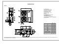
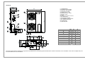
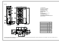
DIMENSIONS ......................................................................................50
TECHNICAL DATA................................................................................53

M0G940E8-00 04/07/08 pag 4
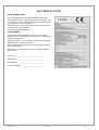
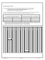
UNIT IDENTIFICATION
SERIAL NUMBER LABEL
The units are identified by the serial number label shown here.
The label lists the type of unit (series and size), serial number, year
of manufacture, number of electrical diagram, main technical data,
logo and address of the manufacturer.
The label is placed on the unit, generally near the electrical panel
and also on the external panelling.
IT MUST NEVER BE REMOVED.
SERIAL NUMBER
This provides unique identification of the machine. It makes it
possible to trace the specific features of the unit and to identify the
components installed in it.
Without this number, it is not possible to identify with certainty the
spare parts that are specific to that unit.
When requesting assistance, always provide the type of machine
and the serial number.
Write them in the space below so that they are readily available
when needed.
Type of unit : _________________________________
Serial number : _________________________________
Wiring diagram : __________________________
Year of manufacture : ___________________________

M0G940E8-00 04/07/08 pag 5
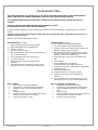
INSTRUCTIONS FOR THE USER
• This is a partial sintex of the information provided in the manual; carefully read this manual
• Carefully read this manual. Keep it with the electrical diagram. Make it available to technicians for servicing.
• Ask the installer for training on start-up, shutdown, changing set points, placing in at-rest status, maintenance, what to do
or not to do in the event of a breakdown.
• Provide for scheduled maintenance by specialized technicians so as to ensure long-lasting operation of the unit.
• If you expect the machine to be shut down for long periods of time, disconnect the electrical power supply. In winter, take
necessary measures to deal with possible freezing (unit and system pipes) .
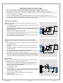
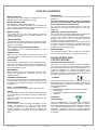
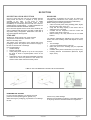
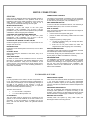
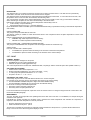
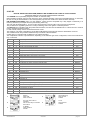
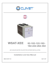
PRINCIPLE OF OPERATION
SUMMER: the cooling cycle allows the transfer of excess indoor heat to the
external environment.
1. The compressor compresses the refrigerant gas, placing it at high pressure
and high temperature.
2. In the external coil, the refrigerant is cooled, and the heat is released into the
environment by means of the fan. This is why the coil needs to be kept clean
and free of obstacles.
3. When it cools, the refrigerant becomes liquid.
4. The expansion valve causes a sudden drop in the pressure of the refrigerant,
which becomes very cold as its volume increases.
5. In the exchanger, the refrigerant evaporates and absorbs the heat from the
water that returns to the system, cooling it.
2
1
3
4
5
6
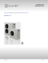
WINTER : the cooling cycle makes it possible to absorb energy (heat at low
temperature) from the external environment and to transfer it to the area to be
heated.
1. The compressor compresses the refrigerant fluid, placing it at high pressure
and high temperature.
2. The 4-way valve reverses the flow with respect to respect to SUMMER
operation.
3. In the plate exchanger, the water that returns to the system absorbs heat
from the refrigerant.
4. As it cools, the refrigerant condenses and becomes liquid.
5. The expansion valve causes a sudden drop in the pressure of the refrigerant,
which becomes very cold as its volume increases.
6. In the external coil, the cold refrigerant evaporates and absorbs heat from the
external air. In this phase, as the coil cools, it may freeze. This is why the
cycle is automatically reversed periodically for a short time so as to defrost it
2
1
3
45
6
7
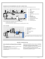
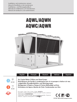
WATER CIRCUIT
The diagram on the side is indicative and includes optional components; check
with the installer about the system configuration used.
1. the electric heaters supplement the heating capacity supplied by the unit;
2. the 3-way valve diverts the water either towards the sanitary hot water
storage or towards the heating equipment;
3. sanitary hot water storage;
4. fan coil heating;
5. if the room needs to be heated, the 3-way valve diverts the water towards the
underfloor piping (all or in part); if instead the underfloor piping is satisfied, it
returns the water directly to the unit;
6. the pump keeps the water in circulation in the underfloor piping
7. underfloor heating
8. the pump returns the water to the unit
123
4567
8

M0G940E8-00 04/07/08 pag 6
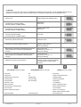
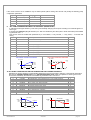
TO DO FOR:
Some functions are active only if they are enabled during installation (remote ON-OFF, remote SUMMER WINTER change,
remote ECO, sanitary hot water, set point compensation). Check with the installer about the configuration used.
Start the unit LONG pressing of the ON/OFF button
Choose the SUMMER mode
possible also by external enabling
(see ELECTRICAL CONNECTIONS)
“SUN” button
Green led on
Choose the WINTER mode
possible also by external enabling
(see ELECTRICAL CONNECTIONS)
“SNOW-FLAKE” button
Green led on
Limit the energetic consumption
Control by external enabling
(see ELECTRICAL CONNECTIONS)
ECO button
Choose the optimal comfort level COMFORT button
Activate the hot sanitary water production
Through remote consent outside the unit
“SNOW-FLAKE” button on
“SUN” led is flashing
Minimize the consumptions maintaining the system at a
safety temperature in WINTER ( MAINTENANCE
function)
Put the unit in OFF
( parameter 45 must be = 1)
yellow led is flashing
Minimize the consumptions maintaining the system at a
safety temperature in SUMMER ( MAINTENANCE
function)
Put the unit in OFF
( parameter 44 must be = 1)
yellow led is flashing
Identify the cause of the unit shutdown
RED LED lit
- flashing: the alarm resets automatically
- on continuously: a manual reset is
necessary
ELECTRICAL CIRCUIT ALARM REFRIGERANT CIRCUIT ALARM WATER CIRCUIT ALARM
Inlet probe HP Flow pump
Outlet probe LP System charged with water
Radiant panel water probe CCMP/VENT Antifreeze alarm
Coil/flow probe HP1 Pre-Alarm Antifreeze PREAlarm
External probe BP1 Pre-Alarm Pump alarm
Pressure 1 probe C1 PREAlarm
Water reset inlet PRad. Cooling limit alarm
External relative humidity probe PRad. Water frost alarm
Phase monitor Coil frost alarm
Electric heater output probe Alarm ?T° incongruous
Electric heater antifreeze alarm
serial faulty alarm serial faulty alarm serial faulty alarm

M0G940E8-00 04/07/08 pag 7
To reset the current alarm
ONLY AFTER THE CAUSE ELIMINATION !
TEST + ON/OFF contemporary for some
seconds
Modify the HOT SANITARY water temperature Control parameter 117
Modify the water temp. in HEATING Control parameter 33
Modify the water temp. in ECO HEATING Control parameter 30
Modify the water temp. in COOLING Control parameter ametro 32
Modify the water temp. in ECO cooling Control parameter 29
Modify the water temp. in MAINTENANCE heating Control parameter parametro 43
Modify the water temp. in MAINTENANCE cooling Control parameter 42
Only by SERVICE
keypad
ALARM
STATUS
SET
COMMON CAUSES OF SHUTDOWN
1. coils dirty - clogged by leaves - nearby obstacles - covered with snow
2. set point too low (in summer) or too high (in winter)
3. water in system is too hot (in summer, for example with machine left off over the weekend) or too cold (in winter)
4. water filter dirty
5. external permissions (remote ON-OFF etc. )
6. water cut-off valves closed
7. system not pressurized - air needs to be vented
8. system pump off
9. circulator pump not running (after seasonal shutdown)
10. unit exchanger dirty
11. fans blocked by snow

M0G940E8-00 04/07/08 pag 8
GENERAL WARNINGS
MANUAL PURPOSE
This manual has been designed to enable the unit to be
installed, started up and maintained correctly.
MANUAL INSTRUCTIONS
It is essential to observe these instructions.
The manufacturer declines all liability for any damage that
may be caused whether directly or indirectly to persons or
things if these instructions are not heeded.
MANUAL STORE
This manual and the unit’s wiring diagram should be
carefully stored so that they are readily available to the
operator when required.
EXPERT PERSONAL
The unit must be installed, tested and maintained by expert
personal who meet the relevant legal requirements (Italian
law No. 46 of 5/3/1990).
LOCAL SAFET REGULATION INSTALLATION
The installation must be performed observing the local
safety regulations.
POWER SUPPLY
Make sure the power supply conforms to the data on the
unit’s rating plate, located inside the door of the main
electrical panel.
PACKAGING
The packaging material (plastic bags, polystyrene foam,
nails, etc.) is potentially dangerous and should therefore be
kept away from children and recycled in compliance with
the local regulations in force.
MAINTENANCE
Before performing any service operations, cut off the power.
Perform the operations in conformity with the local
regulations in force.
PERIODICAL INSPECTIONS
Perform periodical inspections to locate possible loosened
or broken parts. If the repairs are not performed, there will
be a higher risk for things and peoples to become damaged
and injured.
FAULT – POOR OPERATION
Switch off the unit in the event of faults or poor operation.
REPAIR
Only have repairs carried out by a service centre authorised
by the manufacturer, and insist on the use of original spare
parts only.
Failure to comply with the above may compromise the
safety of the unit.
MODIFICATIONS
The manufacturer will not accept any responsibility, and the
warranty will lapse, in the event of electric and/or
mechanical modifications. Any modification which is not
formally authorized, and which does not respect the
instructions given in this manual, will cause the warranty to
lapse.
INTENDED USE
The unit must only be used for the specific purpose it was
designed :
The unit is designed to cool/heat water or a water and
glycol mix for air-conditioning, within the limits defined
in the technical bulletin and this manual.
Any use other than that specified does not imply any
commitment or constraint by the manufacturer in any way
whatsoever.
ADDITIONAL SAFETY PRECAUTIONS
This unit has been especially designed and manufactured
so to prevent any risk to persons and health hazard.
For this reason, design solutions fit to eliminate (where
possible) any cause of risk and sensibly reduce the
probability of danger have been adopted.
Please refer to the "Residual Risks" section of this manual
and strictly observe the behaviour prescriptions listed there
in order to prevent any possible risk that hasn’t been
possible to avoid in the design stage.
DATA UPDATING
The manufacturer may be able to modify the data without
prior notice as a consequence of constant improvements.
REGULATIONS AND
CERTIFICATIONS
UNI EN ISO 9001 CERTIFICATION
Clivet S.p.A., in order to guarantee customer satisfaction,
has chosen the ISO 9001 Quality System as the reference
for all its business activities. This is demonstrated by the
company’s commitment to ongoing improvements in the
quality and reliability of its products; its sales, design,
purchasing, production and after-sales service activities are
the means used to reach such purpose.
CE MARK
Clivet products bear the CE mark, in compliance with the
requirements of the following EC directives, including the
latest amendments, and with the corresponding national
approximated legislation:
• - 98/37/CE
• - 89/336/CEE as modified by the directives 92/31/CEE
and 93/68/CEE
• - 73/23/CEE as modified by the directive 93/68/CEE
• - 97/23/CE
EUROVENT
CERTIFICATION
Clivet is partecipating in the EUROVENT Certification
Programme "Liquid Chilling Packages". Products are listed
in the EUROVENT Directory of Certified Products and in the
site www.eurovent-certification.com. Eurovent Chillers
Certification Programme covers air cooled packaged
chillers up to 600 kW and water cooled packaged chillers up
to 1500 kW.

M0G940E8-00 04/07/08 pag 9
RESIDUAL RISKS
GENERAL
This section lists some of the more common situations
which, being beyond the control of the manufacturer, could
be a source of risk to persons or property.
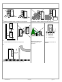
DANGER AREA
The figure below highlights the area in which only
authorised personnel may operate.
• External danger zone, identified by a precise area
around the unit and its vertical projection on the
ground in the case of hanging unit.
• Internal danger zone, identified by the area that can
be entered only after having intentionally removed the
protecting panels or parts of these.
A
B
C
D
A = 1000mm B = 1000mm
C = 1000mm D = 1000mm
HANDLING
If handling operations are undertaken without adopting all
the necessary safety procedures and exercising due care,
the unit can fall or topple, causing damage — possibly
extremely serious — to persons and/or property, and to the
unit itself.
Ensure the unit is handled and manoeuvred as directed on
the packing and in the present manual, and in accordance
with local regulations.
In the event of refrigerant gas escaping, refer to the “Safety
datasheet” for the particular refrigerant.
INSTALLATION
Incorrect installation of the unit can result in water leaks,
accumulation of condensate, escape of refrigerant, electric
shocks, fire, as well as irregular operation or damage to the
unit itself.
Make certain that the installation is carried out only by a
qualified technician, also that the directions contained in
this manual are followed and local statutory regulations
observed.
In the event of the unit being installed in a site where there
is even the slightest risk of inflammable gas escapes and
consequently the possibility of such gases accumulating in
area around the unit, the risk of explosion and fire cannot
be discounted.
Take every care and precaution when selecting the
installation site.
Installation on a structure not able to bear the weight and/or
afford a secure anchorage of the equipment may cause the
unit to fall and/or topple, resulting in damage to persons or
property, or to the unit itself. Make certain that every care
and precaution is taken when positioning and securing the
unit.
If the unit is easily accessible to children, unauthorized
persons or animals, this is a situation that can give rise
accidents and injuries, perhaps serious. Install the unit in a
place where access is allowed only to authorized persons,
or install barriers or guards preventing unauthorized entry.
GENERAL RISKS
A smell of burning, smoke or other indications of serious
irregularity could signal the onset of situations liable to
cause damage to persons or property or to the unit itself.
Isolate the unit from the electrical power supply (red-and-
yellow) switch.
Contact an authorized service centre so that the source of
the problem can be identified and remedied.
Accidental contact with heat exchange coils, compressors,
pressure pipelines or other components can result in
wounding or burns, or both.
Always wear suitable clothing, including protective gloves,
when working in the danger area.
Maintenance or repairs carried out by unskilled operatives
can result in harm or damage to persons and property, or to
the unit itself. Always contact an authorized service centre.
Failure to close the panels of the unit, or to check that all
the fixing screws of the panels are properly tightened, can
result in harm or damage to persons or property, or to the
unit itself.
Verify periodically that all panels are closed and made
properly secure.
In the event of fire, the temperature of the refrigerant can
rise to the point that pressure will exceed safety levels and
perhaps cause fluid to be projected. It may also happen
that parts of the circuit isolated by closed valves will
explode.
Do not stand near safety valves, and never leave the valves
of the refrigerant circuit closed.
ELECTRICAL SYSTEM
If the power line connecting the unit to the a.c. supply is
incomplete, or if the connection is made with cables of
incorrect cross section and/or with insufficiently rated
protective devices, this can result in electric shock, toxicity
hazard, damage to the unit or fire.
All work on the electrical system should be carried out
referring to the wiring diagram and to the directions given in
this manual, and the system itself must be dedicated.
Failure to secure the cover enclosing electrical components
can lead to the infiltration of dust and water, ultimately
causing electric shocks, damage to the unit, or fire.
Always fasten the cover securely to the unit.
If live metal parts of the unit are not connected properly to
the earth system, they can cause electric shock or even
death by electrocution.
Make absolutely certain that the connection to the earth
system is made in accordance with correct practice.
Contact with live parts rendered accessible internally of the
unit when the guards are removed can result in electric
shock, burns or death by electrocution.
Before exposing these parts, make certain the isolating
switch on the power line to the unit is set to the OFF
position and padlocked, and post a warning sign.

M0G940E8-00 04/07/08 pag 10
Contact with parts that could become live when the unit is
started up can result in electric shock, burns or death by
electrocution.
When there is no need for circuits to be powered up, set the
isolating switch on the power line to the OFF position,
padlock it and post a warning sign.
MOVING PARTS
Contact with the fan rotors can cause injury.
Before removing the protective grilles or the fans
themselves, make certain the isolating switch on the power
line to the unit is set to the OFF position and padlocked,
and post a warning sign.
Before removing the protective grilles or the fans
themselves, make certain the isolating switch on the power
line to the unit is set to the OFF position and padlocked,
and post a warning sign.
REFRIGERANT
In the event of safety valves coming into operation and
releasing refrigerant gas, persons in the vicinity can be
injured or suffer toxic effects. Always wear suitable clothing
and protective goggles when working in potential hazard
areas.
In the event of refrigerant gas escaping, refer to the “Safety
datasheet” for the particular refrigerant.
If an open flame or heat source is brought into contact with
the refrigerant, or the pressurized gas circuit should
overheat (e.g. during welding operations), this can cause
explosion or fire. Do not position any heat source within the
hazard area.
Maintenance or repair operations involving welding must be
carried out with the system emptied of refrigerant.
WATER SYSTEM
Defects affecting pipelines, connections or valves and other
control componentry can result in water being leaked or
sprayed from the system, occasioning damage to property
or causing short circuits in the unit.
Make certain all hydraulic connections are securely made,
following the directions given in the present manual.
REFRIGERANT SAFETY CHARTS
R-410A
01 Identification of
the product and
of the supplier
Chart No FRIG 8
Product R-410A
Identification of the supplier. See heading or bottom of page.
No of emergency telephone. See heading or bottom of page.
02 Composition /
information on
ingredients
Substance/ Compound . Compound
Elements / Impurities. It contains the following elements
Difluorometan (R32) 50 % in weight
Pentafluoroetan (R125) 50 % in weight
CEE No Non applicable for mixtures.
Commercial name /
03 Hazard
identification
Hazard identification. Liquefied gas.
Vapours are heavier than air and can cause choking by reducing the oxygen available for breathing.
A rapid evaporation of the liquid can cause freezing.
It can cause cardiac arrhythmia.
04 First aid
measures
Inhalation. Do not administer anything to fainted people.
Take to open air. Administer oxygen or practice artificial breathing if necessary.
Do not administer adrenaline or similar substances.
Contact with eyes. Rinse carefully with plenty of water for at least 15 minutes and consult a doctor.
Contact with the skin. Rinse immediately with plenty of water. Immediately take off all contaminated cloths.
Ingestion. Way of exposure not very probable.
05 Anti-fire
measures
Specific hazards. Pressure increase.
Dangerous combustible products. Halogen acids, traces of carbonyl halogens.
Extinction means. You can use all extinction means available.
Special methods. Cool the containers/tanks with sprays of water.
Special protection means. In close spaces, use the self-breather.
06 Measures against
the accidental
leakages of the
product.
Personal protections. Evacuate the personnel in safety areas. Foresee adequate ventilation. Use means of
personal protection.
Protection for the environment. It evaporates.
Methods for eliminating the product. It evaporates.
07 Handling and
stocking.
Handling and stocking. Assure a sufficient exchange of air and/or a suction system in work areas.
Use only in well-ventilated rooms. Do not breathe vapours or aerosols. Carefully close the containers and
keep them in a cool, dry and well-ventilated place.
Keep in the original containers.
Incompatible products. Explosives, inflammable materials, organic peroxides.

M0G940E8-00 04/07/08 pag 11
08 Check of the
exposition /
personal protection
Personal protection. Assure adequate ventilation, especially in closed rooms.
Control parameters. Difluorometan (R32): Recommended limits of exposition: AEL (8h and 12h TWA) = 1000
ml/m3
Pentafluoroetan (R125): Recommended limits of exposition: AEL (8h and 12h TWA) = 1000
ml/m3
Protection of respiratory tract. For the rescue and for service work in the tanks, use an autonomous breather. Vapours are
heavier than the air and can cause choking by reducing the oxygen available for breathing.
Protection for the eyes. Total protection glasses.
Protection for the hands. Rubber gloves.
Hygienic measures. Do not smoke.
09 Chemical -physical
properties.
Relative density, gas (air=1) Heavier than air.
Solubility in water (mg/l). Not known, but probably very low.
Aspect. Colourless liquefied gas.
Smell. Simile to ether.
Point of ignition. Don’t ignite.
10 Stability and
reactivity.
Stability and reactivity. No decomposition if used following the instructions.
Materials to avoid. Alkaline metals, earth alkaline metals, granulated metal salts, Al, Zn, Be etc. in powder.
Dangerous decomposition products. Halogen acids, traces of carbonyl halogens.
11 Toxicological
information
Local effects. Concentration substantially above the TLV value (1000 ppm) can cause narcotic effects. Inhalation of products
at high concentration decomposition can cause respiratory insufficiency (pulmonary edema).
Long-term toxicity. It has shown no carcinogenic, teratogen or mutagenic effects on animal experiments.
Specific effects. A rapid evaporation of the liquid can cause freezing. It can cause cardiac arrhythmia.
12 Ecological
information
Effects connected to ecotoxicity
Pentafluoroetan (R125) Potential of global heating of halocarbides; HGWP; (R-11 = 1) = 0.84
Potential of ozone impoverishment; ODP; (R-11 = 1) = 0
13 Disposal
considerations
General considerations. Do not drain where the accumulation can be dangerous
Usable as reconditioning.
Depressurized containers should be given back to the supplier.
Contact the supplier if the use of instructions is necessary.
14 Transport
information
Designation for the transport LIQUEFIED GAS N.A.S
(DIFLUOROMETAN, PENTAFLUOROETAN)
UN No 3163
Class/Div 2.2
ADR /RID Nr 2, 2°A
No hazard ADR/RID 20
ADR Label. Label 2: not toxic gas not inflammable.
CEFIC Groupcard 20g39 - A
Other information for the transport. Avoid the transport on vehicles where the loading zone is not separated from the driver
compartment.
Verify that the driver is informed on the potential risk of the load and that he knows what to do in case of an accident or
emergency.
Before starting the transport, verify that the load is well fixed and:
Verify that the container valve is closed and does not leak
Verify that the blind cap of the valve, if supplied, is correctly assembled.
Verify that the cap (if supplied) is well assembled and that there is adequate ventilation
Verify that the norms in force are respected.
15 Information on the
norms in force
The product must be labelled according to the 1999/45/CE normative.
Observe the following norms, the relevant updating and the applicable modifications:
Circulars no.46/79 and 61/81 of the Work Ministry: risks connected to the use of products containing aromatic ammines.
Law Decree no. 133/92 : Norms relevant to the draining of dangerous substances in water
Law Decree no. 277/91: Protection of workers for noise, lead and amianthus
Law 256/74, Ministerial Decree of 28th Jan. 1992, Legislative Decree no 52 of 3rd Feb. 1997, Ministerial Decree of 28th Apr.
1997 and following modifications: Classification, packaging and labelling of compounds and dangerous substances
Decree of the Republic President no.175/88, following modifications and updating: Activities with risks of serious accidents
(Seveso Law)
Decree of the Republic President no 203/88: Emissions in the atmosphere
Decree of the Republic President no.303/56: Hygiene of work
Decree of the Republic President no.547/55: Norms concerning the accident prevention
Legislative Decree. No.152 of 11th May 1999: Protection of waters.
16 Other information Suggested uses. Refrigerant.
High concentrations can cause asphyxia.
Keep in a dry and well-ventilated place.
Do not breathe in the gas.
The asphyxia risk is often under-evaluated and must be put into evidence during the operator’s training.
Verify that all national and regional regulations are observed.
Before using this product in any new process or experiment, a deep study about the safety and the product compatibility with the materials
must be performed.
The above information is based on our present know-how and describes the product considering the safety needs. However, they do not
represent a guarantee and a warranty of the qualities in a juridical sense. Everyone is personally responsible for the observation of these
norms.
Information present in this document is valid at the time of printing. The company is not responsible for any damages caused by the incorrect
use of the product and/or for the use in conditions different from the conditions suggested.

M0G940E8-00 04/07/08 pag 12
RECEPTION
INSPECTION UPON RECEPTION
Check on arrival that the unit has not suffered damage
during transit and that it is complete in every part as
specified in the order. In the event of visible
damage/deficiencies being discovered, make a note
immediately on the delivery document with the comment:
CONDITIONAL ACCEPTANCE — CLEAR EVIDENCE OF
DEFICIENCIES/DAMAGE DURING TRANSIT
Inform both the supplier and the carrier of the details by fax
and by registered mail with advice of receipt not later than 8
days after taking consignment. Notifications sent after 8
days have elapsed will be ignored.
STORAGE
Shelter from: direct sunlight, rain, sand and wind
Temperature: maximum 60°C minimum -10°C
Maximum humidity: 90%
The respect of the instructions on the exterior side of the
packaging assures the physical and functional integrity of
the unit for the final user’s advantage.
It is recommended to:
• Handle carefully
• Keep in a dry place
• Avoid putting other objects on top of the unit (respect
the limits of levels of superimposition shown in the
package)
• Avoid placing the unit with thermoretractable protection
under the sun since the pressure of the circuits can
assume values which activate the safety valves.
HANDLING
The operation of handling the unit must be carried out
respecting the instructions of the safety norms in force
(Legislative Decree 626/94 and following modifications)
Before starting the handling operations:
• Value the critical points during handling (stairs, flights,
disconnected routes, doors, etc)
• Verify that the lifting capacity of the means used is
adequate to the unit weight
• Consider that the barycentre could be moved with
respect to the center of the unit
• Before starting to lift, verify that the unit is at a stable
balance
The following examples are indications; the choice of the
means and of the handling modes will depend on factors,
such as:
• The unit weight
• Type and overall dimensions of the unit
• Place and route for the handling (dirt yard, asphalted
square, etc)
• Condition of the place of destination (roof, square, etc)
• Handling distance characteristics (distances, flights,
steps, doors)
LABELS / YELLOW BRACKETS SHOW THE LIFTING POINTS
REMOVING THE PACKING
For removing the packaging, use specific personal
protection for the operator (gloves, glasses, etc.).
While removing the packaging, pay attention not to damage
the unit.
Check for any visible damage.
Dispose of the packaging by taking it to specialist collection
or recycling centres in accordance with local regulations.

M0G940E8-00 04/07/08 pag 13
POSITIONING
GENERAL
For installing air-conditioning systems, it is necessary to
consider the following:
• the technical spaces necessary for the machine and
system
• the place where the machine will be installed
• the transport of thermal carrier fluids and relevant
connections to the unit:
o water
o air
o refrigerant (unit in more sections)
• electrical connections
If these aspects are not evaluated carefully, they can affect
the performances and the working life of the unit.
FUNCTIONAL CLEARANCES
When placing the unit, please respect the functional
clearances indicated in DIMENSIONS section.
The functional spaces need to be observed because of the
following:
• to guarantee the good operation of the unit
• to allow the performance of all maintenance operations
• to protect the authorized operators and exposed
people
If more units are placed close to one another, the functional
spaces must be doubled.
POSITIONING
1. The units are designed for OUTDOOR installations,
performed in fixed positions and in areas accessible
only to qualified and authorized personnel
2. SAFETY VALVE (only if present on the unit) : the
installer is responsible for evaluating the opportunity
of installing drain tubes, in conformity with the local
regulations in force ( EN 378 )
3. Install the unit raised from the ground
4. avoid installations in places subject to flooding
5. Consider the maximum level which can be reached by
snow
6. Verify that the fixing/supporting points are level and
suitable to support the weight of the unit (see the
weight and the weights distribution)
7. It is recommended to put the unit on specific
antivibration devices
Each support point of the unit sustains a different
weight. Therefore, each anti-vibration device is sized
for a specific support point, and can only be placed
there. The anti-vibration devices must therefore be
placed in accordance with the instructions provided
with them and with the dimensional drawings in which
the support points are indicated by W1 , W2 , W3 etc .
On each anti-vibration device (if provided by CLIVET),
its identifying code is stamped, for example C6100100
Flexible joints are necessary on all the hydraulic/
aeraulic connections (the joints are not supplied by
Clivet)
8. Anchor the unit to the ground; foresee windbreak
barriers in case of places where there are strong
prevalent winds .
9. During winter operation, a considerable amount of
condensation water is produced, which must be
removed from the unit.
Make sure that removal of condensation water does
not create any problems for persons or property, such
as dripping from balconies, onto walkways, etc.
For long periods of heat pump operation with external
temperature below 0°C, the condensation might
freeze, causing a build-up of ice. The installation of
anti-freeze heating elements should be considered.
For the units that are equipped with a condensation
drain, this is shown on the dimensional drawing.
10. The choice of the location of the unit is of fundamental
importance for correct operation; to avoid:
− obstacles that block the flow of air
− difficulty in air circulation
− leaves or other objects that may block the
exchanger coils
− winds that contrast or excessively assist the air
flow
− phenomena of stratification or air re-circulation
− nearby sources of heat (chemney, extractor ecc)
− positioning under the round level or near very high
walls
The previous situations cause working anomalies or
stop the machine and cause:
− during SUMMER operation, increase of the
condensation pressure with the decay of
performances and possible stops due to high
pressure.
− during WINTER operation, decrease of the
evaporation pressure with increase to the amount
of defrosting and consequent decay of the
performances and possible stops due to high
pressure

M0G940E8-00 04/07/08 pag 14
Install the unit raised off the ground and on a sturdy base. Consider the maximum depth that snowfall might reach.
A
!
2 A
!
!
!
Tree
1
3
2
1. elastic joint
2. floating floor
3. soundproofing
Consider clearances and direction of expelled air.
Keep the coil clean. Avoid
zones with leaves / dirt /
corrosives.
Prevent the transmission of
vibrations.
!
Provide windbreaks in locations with strong winds

M0G940E8-00 04/07/08 pag 15
WATER CONNECTIONS
GENERAL
Piping must be designed with the least possible number of
bends and head variations. If the pressure chute of the
installation is above the useful prevalence of the pump, the
water delivery capacity is reduced as well as, as a
consequence, the thermal exchange and the yield.
INTERCEPTING VALVES
Install on the input and output of the user parts
(exchangers, coils, humidifiers, etc) So that it will be
possible to carry out all the service operations and possible
substitutions without emptying the installation.
PRESSURE AND TEMPERATURE INDICATOR
Install on the input and output of the user parts
(exchangers, coils, humidifiers, etc) So that it will be
possible to carry out all the service operations.
AUTOMATIC OR MANUAL ESCAPE VALVES
Install the highest points of tubes in a way that the air can
escape form the circuit.
BLEEDING COCK
Install them at the lowest points of the circuit, so as to allow
emptying.
LEAKAGE TESTS
Before performing the insulation of the tubes, carry out a
leakage test.
TUBE INSULATION
All tubes of water must be insulated so that to avoid the
formation of condensation and thermal dispersions along
the tubes themselves. Verify that the insulation is the
vapour coil type. The connections for the air escape and for
the emptying must be out of the insulating thickness to
assure the accessibilità.
CONNECTIONS SUPPORTS
The weight of the hydraulic connections must be supported
in the exterior of the unit so as not to stress the connections
of user devices (exchangers, coils, humidifiers, etc ) .
ANTI-VIBRATION DEVICES
In case of units with anti-vibration devices, it is necessary to
assemble elastic joints, even on water connections.
RISK OF FREEZE
If the unit and the relevant water connections are subject to
temperatures near 0°C:
• mix the water of the system with glycol
• protect the tubes with heating cables under the tubes
insulation
• empty the system by verifying that:
o no taps are closed so they can not trap the water,
even after emptying
o there are no low points where the water can
stagnate even after emptying; blow if necessary
INTALLATION EMPTYING
The refilling of the water present in the installation increase
the oxidation phenomena and lime deposits.
If necessary empty only the interested system section and
anyway empty or refill the installation if necessary .
EXPANSION TANK
The installation must be kept at the right pressure by both
an expansion tank and a combined valve of pressure
reduction and discharge; if the components are present on
the unit, they must be installed on the installation. The
expansion tank must be dimensioned in function of the
water in the installation.
EXCHANGER USE SIDE
FILTER
It is very important for the water to be free of impurities. If it
is not, the efficiency of thermal exchange is diminished. In
worst cases, the exchanger can be irreparably damaged. If
the filter is not present on the machine, it must be
immediately installed upstream from the unit, in a position
which can be easily reached for cleaning.
The filter mesh must be :
• < 1 mm unit with 1 compressor
• < 1.5 mm multicompressor unit.
FLOW SWITCH
The flow switch must be present as a component of the
system, so as to ensure shutdown of the unit if water is not
circulating. It must be installed in a straight tract of the
tubes, not near the elbows, which can generate harmful
turbulence
UNFREEZABLE LIQUIDS
If the unit is used when the water temperature is lower than
+ 4°C, avoid the formation of ice by using unfreezable
liquids (ex. Ethilenic Glycol) in the necessary percentage.
The use must also be determined for ambient temperatures
near 0°C .
ANTIFREEZE RESISTANCES
If the unit is equipped with antifreeze resistances on the
exchanger side (standard or optional according to the
models), verify that they are electrically fed during periods
that the machine is stopped (night, weekends, long stops)
WASHING THE SYSTEM
Carefully wash the system by using clean water and
discharge it before connecting the unit.

M0G940E8-00 04/07/08 pag 16
DIAGRAM OF RECOMMENDED USE SIDE CONNECTION
Depending on the type of machine and the selected setup, some components may be integrated into the unit.
P
9
11
14
8
F
2
3
5
12
7
6
4
8
1
10
13
P
7
1. Charged system pressure switch
2. vent
3. pump
4. expansion tank
5. safety valve
6. flow switch
7. pressure switch / thermometer
8. filter
9. filling valve
10. antivibration joints
11. user side exchanger
12. Differential pressure switch
13. Discharge cock
14. inertial storage tank
The accumulation tank is necessary in the event of the following:
• the water in the system is very low
• the unit will not be used in a private house (in an industrial process or other)
USE SCHEMA
8
123
4567
8
1. Heating integration
2. 3-ways ON-OFF sanitary H2O
3. sanitary boiler
4. fancoil
5. 3-ways radiant panels
6. radiant pump
7. radiants
8. pump
for more details see the ELECTRICAL DATA section and
the SYSTEM SCHEMA WITH ACCESSORIES at page
26
WINTER CONDENSATION
When a heat pump is running it produces a considerable
amount of water due to the defrosting cycles of the external
coil.
The condensation must be eliminated in a manner to avoid
wetting pedestrian areas.
With extensive very cold outdoor temperatures,
condensation could freeze and block the flow, causing a
slow build-up of ice;
therefore special attention must be paid to eliminating
condensation, raising the unit off the ground and evaluating
whether antifreeze elements should be installed
For units with condensation trays, refer to the dimensional
diagrams to calculate the condensation discharge.
For units without condensation tray, evaluate the suitability
of placing a tray beneath the unit base.

M0G940E8-00 04/07/08 pag 17
ELECTRICAL CONNECTION
GENERAL
The characteristics of the electrical lines and relevant
components must be determined by SPECIALIZED
PERSONNEL ABLE TO DESIGN ELECTRICAL
INSTALLATIONS; moreover, the lines must be in conformity
with professional procedures and the regulations in force.
All electrical operations should be performed by trained
PERSONNEL HAVING THE NECESSARY REQUISITES
UNDER LAW and being informed about the risks relevant to
these activities.
Before performing any operation on the electrical system,
make sure that the unit supply line is SELECTED AT
START.
The earth connection must be made prior to other electrical
connections.
For all electrical type operations, REFER TO THE
ELECTRICAL DIAGRAM ATTACHED TO THE UNIT; the
number of the diagram is shown on the registration plate
positioned on the electrical board or next to it.
The electrical diagram should be carefully kept together with
this manual and should be AVAILABLE FOR FUTURE
INTERVENTION ON THE UNIT.
LINE OF UNIT POWER SUPPLY
The ELECTRICAL DATA OF THE UNIT are shown in the
technical chart of this manual and on the unit registration
plate. The presence of accessories can vary according to
the unit; the electrical data shown in the technical chart refer
to standard units. In the event of differences between the
data of the registration plate and the data shown in this
manual, as well as in the technical chart, please refer to the
DATA SHOWN IN THE REGISTRATION PLATE.
The protection device of the unit power supply line should
break off the short circuit power whose value should be
determined according to the plant features.
The section of supply cables and protection cable must be
seized according to the characteristics of the protections
used.
SIGNALS / DATA LINES
Do not overpass the maximum power allowed, which varies,
according to the type of signal.
Lay the cables far from power cables or cables having a
different tension and that are able to emit electromagnetic
disturbances.
Do not lay the cable near devices which can generate
electromagnetic interferences.
Do not lay the cables parallel to other cables; cable
crossings are possible, only if laid at 90°.
Connect the screen to the ground, only if there are no
disturbances
Assure the continuity of the screen during the entire
extension of the cable.
Observe, if any, the requirements about impendency,
capacity, attenuation
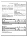
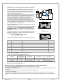
STANDARD UNIT ELECTRICAL DATA
VOLTAGE: 230/1/50
SIZE 21 31 41 51
F.L.A. FULL LOAD CURRENT AT MAX ADMISSIBLE CONDITIONS
F.L.A. - Pump A 1,18 1,18 1,18 2,02
F.L.A. - Total A 15,76 19,36 23,96 30,64
F.L.I. FULL LOAD POWER INPUT AT MAX ADMISSIBLE CONDITION
F.L.I. - Pump kW 0,27 0,27 0,27 0,4
F.L.I. - Total kW 3,5 4,3 4,9 6,9
M.I.C. MAXIMUM INRUSH CURRENT
M.I.C. - Value A 63,26 84,26 99,26 133,64
power supply 230/1/50 Hz +/-6%
The pump is included in the total values calculation
for non standard voltage please contact Clivet technical office
The units are compliant with the provisions of European standards CEI EN 60204 and CEI EN 60335.
VOLTAGE: 400/3/50+N
SIZE 21 31 41 51
F.L.A. FULL LOAD CURRENT AT MAX ADMISSIBLE CONDITIONS
F.L.A. - Pump A 1,18 1,18 1,18 2,02
F.L.A. - Total A 7,1 9,2 9,9 13,9
F.L.I. FULL LOAD POWER INPUT AT MAX ADMISSIBLE CONDITION
F.L.I. - Pump kW 0,27 0,27 0,27 0,4
F.L.I. - Total kW 3,2 4 4,8 6,8
M.I.C. MAXIMUM INRUSH CURRENT
M.I.C. - Value A 34,3 37,3 50,3 67,6
power supply 400/3/50 (+ NEUTRAL) +/- 6%
Maximum Phase Unbalance: 2%
The pump is included in the total values calculation
for non standard voltage please contact Clivet technical office
The units are compliant with the provisions of European standards CEI EN 60204 and CEI EN 60335.

M0G940E8-00 04/07/08 pag 18
CONNECTION TO THE MAINS
1. Make sure that the sectioning device at the beginning of the unit’s power line is opened, locked and equipped with a signal.
2. Open the general line disconnecting switch (if present)
3. Verify that the net is in conformity with the data shown in the registration plate placed on the electrical board.
4. Check the dimensional drawing for the input of the electrical lines
5. Take away the closing plate placed on the electric board (ONLY IF PRESENT) and drill a hole through it to pass the
cables through)
6. Protect the cables, using the fairlead of an adequate size.
7. Using the layout of the electrical diagram, single out the connecting terminals of the electrical supply cables, of the neutral
(if foreseen) and the PE protection cable
8. Connect the cables to the relevant terminal boards
9. Before supplying power to the unit, make sure that all the safety devices that were removed during electrical connections
are positioned again.
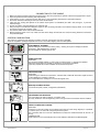
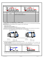
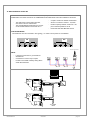
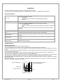
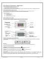
SYSTEM COMPOSITION
The system is composed of the following modules; some are optional that could be not installed.
Some are supplied in packages separate from the unit: check the shipping document descriptions
Test
Comfort
ECO
ELFOENERGY
!
!
!
USER AMBIENT TERMINAL
Permits setting the unit function modes (cooling – heating, ECO) and to display the alarms
(ELECTRIC, REFRIGERATOR, WATER).
This is standard on certain types of unit
LN9192
STATUS
SET
ALARM
2
1
REMOTE KEYPAD
OPTIONAL
The interface terminal enables to control every machine function, to program the different
adjustment parameters and possibly to display the unit statuses and alarms.
It remotely repeats all functions available on the machine keyboard
SERVICE KEYPAD
OPTIONAL
Useful during the maintenance operations; it is fitted with a cable with automotive rapid connector
for the utilisation in proximity to the unit.
The functionalities are analogous to the remote keypad ones.
MAIN ADJUSTMENT MODULE
It controls unit (inlets, outlets, configuration parameters)
EXPANSION PLUG-IN MODULE
It is connected to the main module by a coupling comb.
This may be fitted on the unit depending on the unit type and the accessories that are installed.
81234567
CN2
1210911
16
+5V
13 14 15
gnd
1917 18 2120
SERIALE
TTL / RS485
CN1
gnd 12VAC
+-
SERIAL CONVERTER TTL/RS485
OPTIONAL
Plugged-in in the main module on the electric board (see lay in the wiring diagram). It is possible
to connect up to 127 units with a single supervision system.
The connection with a PC must use a RS485/232 converter; the serial line RS232 can be max. 10-
m long.
CONNECTIONS:
make reference to the electrical panel and to the SIGNALS AND DATA LINES paragraph

M0G940E8-00 04/07/08 pag 19
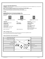
FUNCTIONAL CONNECTIONS
FOR ALL THE CONNECTIONS MAKE REFERENCE TO THE ELECTRICAL PANEL SUPPLIED WITH UNIT
Use voltage-free remote control devices that are suitable to commutate very low loads (12V, 10mA)
Few inputs must be activated by configuration parameters whose access is reserved to authorized assistance centres (in order
to avoid unauthorized modifications)
1. remote ON / OFF
2. remote SUMMER / WINTER
3. remote SECOND SET POINT (ECO )
4. Machine OPERATION / SHUTDOWN SIGNAL
5. REMOTE KEYPAD
6. ELECTRIC INTEGRATION during heating
7. SANITARY HOT WATER
8. UNDERFLOOR HEATING
9. SET POINT COMPENSATION for outside temperature/enthalpy
10. SET POINT COMPENSATION with 4-20 mA signal
11. interface via RS485
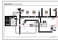
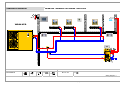
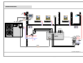
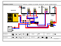
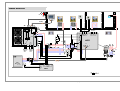
12. SYSTEM SCHEMA WITH ACCESSORIES
• heat pump + radiant panels + domestic hot water page 26
• heat pump + fancoil + domestic hot water page 28
• heat pump + radiators + radiant panels + domestic hot water + boiler page 30
1. ON / OFF FROM REMOTE CONTROL
Generally the unit is delivered with bridged terminals; if the control is not used, bridge terminals.
2. CHANGING FROM SUMMER TO WINTER USING THE REMOTE CONTROL
This function is activated with the 163 remmode = 1 parameter.
Selection switch open – unit in heating mode, selection switch closed – unit in cooling mode, this way the keyboard or
supervisor unit selection is deactivated.
3. SECOND SET POINT FROM REMOTE CONTROL (ECO)
Use of a second set point (par 29 cooling, par 30 heating), usually higher in summer and lower in winter (ECO). The
commutation can be also performed manually by keypad.
The SANITARY HOT WATER option may entail modifications of the input in question: see the relative section.
4. SIGNALIZATION OF MALFUNCTIONING/ UNIT FUNCTIONING
Remote signalisation of the proper function (ex. green light) or signalisation of blocks of the machine (ex. red light).
Maximum voltage at the terminal ends is 24v ac and maximum power is 1A (ac1) .
5. REMOTE KEYPAD
Max. Length 100 metres
VOLTAGE 230/1/50
Signal conductor number 2 + shield
Min. length 0.34 mm2

M0G940E8-00 04/07/08 pag 20
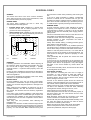
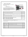
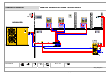
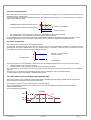
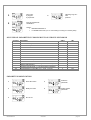
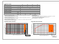
6. ADDITIONAL HEATING ELEMENT
It is possible to control an external element for additional
heating, typically electric heaters.
The control can be:
• ON-OFF ( max 1 A )
• modulating WITH SIGNAL 0-10 V
(in this case a plug-in expansion module is necessary, an
optional that must be assembled by the customer (refer to the
instructions in the kit) and enabled with the parameter 140=1
The diagram on the side is indicative: check the position of the
water connections on the dimensional drawing of the unit or on
the adhesive labels on the unit itself
T out1
T ext
O - 10V
ON -OFF
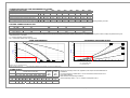
The parameters 178 and 179 can be used to select the behaviour of the heaters: P 178 P 179
AS AN ADDITIONAL ELEMENT ONLY
the heaters are considered as a second power step 1 0
IN REPLACEMENT OF THE COMPRESSOR
the heaters operate only when the compressor is disabled due to an external temp. lower than
par. 180
1 1
MAIN ADJUSTMENT UNIT IN HEATING MODE
in heat pump mode the compressor is disabled 2 1
POWER LIMITATION ACCORDING TO EXTERNAL TEMPERATURE
the following behaviour occurs as the external temperature decreases:
1st Zone = Compressor Enabled / Heaters Disabled
2nd Zone = Compressor Enabled / Heaters Enabled
3rd Zone = Compressor Disabled / Heaters Enabled
2 2
It is necessary to declare the presence of the outlet probe Tout 1 with par. 70 = 1.
This probe becomes the reference for heat adjustment in heating mode; furthermore it manages the antifreeze protection
for this part of the system.
par Description Meaning value
70 Tout1En Enables output probe
140 PlugInEn Enables PLUG-IN presence . 1=YES / 0=NO
177 PotRes Power provided by the additional heaters 100
178 ModeHeater Enable compressor operation in heating 0
179 LimPotTextEn Enable capacity limit for ext. temperature 0
180 LimText Ext. temperature limit for compressor operation 0
181 IstRes Differential on LimText value for heaters activation 5
Page is loading ...
Page is loading ...
Page is loading ...
Page is loading ...
Page is loading ...
Page is loading ...
Page is loading ...
Page is loading ...
Page is loading ...
Page is loading ...
Page is loading ...
Page is loading ...
Page is loading ...
Page is loading ...
Page is loading ...
Page is loading ...
Page is loading ...
Page is loading ...
Page is loading ...
Page is loading ...
Page is loading ...
Page is loading ...
Page is loading ...
Page is loading ...
Page is loading ...
Page is loading ...
Page is loading ...
Page is loading ...
Page is loading ...
Page is loading ...
Page is loading ...
Page is loading ...
Page is loading ...
Page is loading ...
Page is loading ...
Page is loading ...
Page is loading ...
Page is loading ...
Page is loading ...
Page is loading ...
-
 1
1
-
 2
2
-
 3
3
-
 4
4
-
 5
5
-
 6
6
-
 7
7
-
 8
8
-
 9
9
-
 10
10
-
 11
11
-
 12
12
-
 13
13
-
 14
14
-
 15
15
-
 16
16
-
 17
17
-
 18
18
-
 19
19
-
 20
20
-
 21
21
-
 22
22
-
 23
23
-
 24
24
-
 25
25
-
 26
26
-
 27
27
-
 28
28
-
 29
29
-
 30
30
-
 31
31
-
 32
32
-
 33
33
-
 34
34
-
 35
35
-
 36
36
-
 37
37
-
 38
38
-
 39
39
-
 40
40
-
 41
41
-
 42
42
-
 43
43
-
 44
44
-
 45
45
-
 46
46
-
 47
47
-
 48
48
-
 49
49
-
 50
50
-
 51
51
-
 52
52
-
 53
53
-
 54
54
-
 55
55
-
 56
56
-
 57
57
-
 58
58
-
 59
59
-
 60
60


CLIVET WSAN-XEE Series Installation and Use Manual
- Category
- Split-system air conditioners
- Type
- Installation and Use Manual
Ask a question and I''ll find the answer in the document
Finding information in a document is now easier with AI
Related papers
-
 CLIVET WSAT-XEE 162 Installation and Use Manual
-
 CLIVET XSC 110D Installation, Use And Maintenance Manual
-
 CLIVET 2.300 Installation and Use Manual
-
 CLIVET CF-V 31 Installation and Use Manual
-
 CLIVET WSAN-XIN131 Installation guide
-
 CLIVET SCREWLINE3 MDE-SL3 290.1 Installation guide
-
 CLIVET WSHN-XEE2 27.2 Installation guide
-
CLIVET ELFOControl2 Installation, Configuration And Use Manual


Other documents
-
Western MU ECHOS A HP Installation and Operating Instructions
-
-
-
 SystemAir SYSCROLL 450 Air EVO CO Owner's manual
-
 SystemAir AQWR Installation and Maintenance Manual
-
Strebel ASX-VPD Installation, Operating & Maintenance Manual
-
 SystemAir AQVH 140 Owner's manual
-
-
-
SystemAir SYSCROLL 280 Air EVO RE Owner's manual


