Page is loading ...

Crestron Isys™ TPS-5000L
12 Inch Lectern/Wall Mounted Touchpanel
Operations Guide

This document was prepared and written by the Technical Documentation department at:
Crestron Electronics, Inc.
15 Volvo Drive
Rockleigh, NJ 07647
1-888-CRESTRON
All brand names, product names and trademarks are the property of their respective owners.
©2003 Crestron Electronics, Inc.

Crestron Isys™ TPS-5000L 12 Inch Lectern/Wall Mounted Touchpanel
Contents
12 Inch Lectern/Wall Mount Touchpanel: Crestron Isys™ TPS-5000L 1
Introduction ...............................................................................................................................1
Features and Functions................................................................................................ 1
Specifications ..............................................................................................................3
Physical Description....................................................................................................4
Industry Compliance ................................................................................................... 7
Setup .......................................................................................................................................... 7
Network Wiring........................................................................................................... 7
Identity Code ............................................................................................................... 8
Configuring the Touchpanel........................................................................................8
Hardware Hookup .....................................................................................................16
Touchpanel Mounting Options.................................................................................. 19
Touchpanel Removal................................................................................................. 22
Recommended Cleaning............................................................................................22
Programming Software............................................................................................................23
Programming with the Crestron AppBuilder............................................................. 24
Programming with SIMPL Windows
......................................................................24
Programming with VisionTools™ Pro-e................................................................... 28
Reserved Join Numbers.............................................................................................32
MultiByte International Characters ...........................................................................35
Uploading and Upgrading........................................................................................................ 36
Communication Settings ...........................................................................................36
Uploading a SIMPL Windows Program.................................................................... 38
Uploading a VT Pro-e Project ...................................................................................40
Firmware Upgrade..................................................................................................... 41
Problem Solving ...................................................................................................................... 43
Troubleshooting......................................................................................................... 43
Further Inquiries ........................................................................................................44
Future Updates ..........................................................................................................44
Appendix A: RS-232 Protocol................................................................................................. 45
Appendix B: Cutout Detail of Supplied Template.................................................................. 47
Appendix C: Configuring the RS-232 Port for Use................................................................ 48
Obtaining Communications.......................................................................................48
Configuration Options............................................................................................... 48
RS-232 Port Configuration........................................................................................48
Software License Agreement................................................................................................... 50
Return and Warranty Policies .................................................................................................. 52
Merchandise Returns / Repair Service ......................................................................52
CRESTRON Limited Warranty.................................................................................52
Operations Guide - DOC. 5783A Contents • i


Crestron Isys™ TPS-5000L 12 Inch Lectern/Wall Mounted Touchpanel
12 Inch Lectern/Wall Mount
Touchpanel: Crestron Isys™
TPS-5000L
Introduction
Features and Functions
The TPS-5000L series packs all the power and performance of an Isys panel in a
stylish lectern or wall-mount model. Its size and capabilities make it perfect for the
conference room and home theater.
These touchpanels are available with two different faceplate colors: black, or white.
The suffixes ‘B’ or ‘W’ respectively denotes color; i.e., TPS-5000LB is a touchpanel
with a black faceplate. For simplicity within this guide, color suffix is omitted.
Featuring a 12 inch (30.5 cm) active matrix display the TPS-5000L uses the 65,536-
color Isys engine which allows all graphics to be displayed with incredible
brightness and depth.
TPS-5000L Functional Summary
• 12" (30.1 cm) diagonal active matrix color display
• 800 x 600 Native Screen Resolution
• 16 Bit non-palette graphics, over 64,000 colors
• 4 Mb of Flash, expandable to 32 Mb with Crestron
®
plug-in memory
modules & 8 Mb of DRAM Memory
• Unique modular system allows configuration of capabilities simply by
adding expansion cards for video, graphics and Internet
• Displays SVGA RGB video at native resolution with optional
TPS-XVGAL interface card
• Displays one NTSC/PAL/S-video/composite video source with 256,000
colors with optional TPS-VIDL-1 expansion card
(continued on next page)
Operations Guide - DOC. 5783A 12 Inch Lectern/Wall Mount Touchpanel: Crestron Isys™ TPS-5000L • 1

12 Inch Lectern/Wall Mounted Touchpanel Crestron Isys™ TPS-5000L
TPS-5000L Functional Summary (continued)
• Displays two NTSC/PAL/composite video (or one S-video source) with
256,000 colors with optional TPS-VIDL-2 expansion card
• 10/100 BaseT (full/half duplex) Ethernet capabilities with optional
TPS-ENETL expansion card. Supports dynamic and static IP
addressing
• Up to 4,000 digital and analog signal joins; Up to 999 serial signal join
Built-in micro
s
• phone, mixer, amplifier, stereo speakers, and line-level
• uce memory requirements, providing optimal
• n, slider control, and icon configurations, including
s
ble fonts – proportional and non-proportional
• Foreign language text
input/output
• Stores and plays WAV files
• Local RS-232 port for console control
Pop-up sub panels to red
speed and performance
Multiple butto
multi-mode objects
• Fast graphics performance: imported photographs, drawings, and icon
• Support for downloada
Multiple graphics can be displayed on the TPS-5000L without any shift in color
depth or quality. The touchpanel can support real-time video with the optional
TPS-VIDL-1 or TPS-VIDL-2 cards, RGB computer graphics with the optional
TPS-XVGAL RGB Interface card, and 10/100 BaseT TCP/IP network
communications with the optional TPS-ENETL Ethernet module.
The TPS-5000L's audio capabilities include stereo audio speakers that offer volume
control, a built-in microphone with line-level output, built-in WAV sound file
capability and line-level input for other audio sources.
The purpose of the TPS-5000L touchpanel is to replace large, complicated hard-
wired panels in either a Cresnet
®
system or an RS-232 system with a series of
simpler screens each specific to the control problem at hand. Thus, a very large
number of functions can be made available to the user without the confusion
associated with hardware panels of that complexity. Icons, graphics, and text can
dramatically increase any user's comprehension of the control environment. Devices,
functions, and control zones are quickly organized and more easily accessed.
The TPS-5000L has the ability to transmit touch coordinates when "RS-232 Port for
Touch Output" is selected. Currently Telestrator devices are supported on the
TPS-5000L. Refer to the "RS-232 Menu" section of "Configuring the Touchpanel"
on page 11 and “Appendix C: Configuring the RS-232 Port for Use” on page 48 for
instructions on selecting this feature.
2 • 12 Inch Lectern/Wall Mount Touchpanel: Crestron Isys™ TPS-5000L Operations Guide - DOC. 5783A

Crestron Isys™ TPS-5000L 12 Inch Lectern/Wall Mounted Touchpanel
Specifications
The following provides a summary of specifications for the TPS-5000L touchpanel.
Specifications for the TPS-5000L Touchpanel
SPECIFICATION DETAILS
Power Requirements
(without cards)
1
20 Watts (0.83 Amp @ 24 VDC)
Default NET ID 03
Timeout
Adjustable from 0 to 120 minutes (Default = 15
min.)
Signal Join Maximums 4000 Digital and Analog, 999 Serial
Control System Update
Files
,2,3,4
2-Series Control System Version C2-2004.CUZ or later
3
CEN/CN-TVAV Version 51130V.UPZ or later
4,5
CNMSX-AV/PRO Version 51125X.UPZ or later
4,5
CNRACKX/-DP Version 51125W.UPZ or later
4,5
CNMS, CNRACK,
CNLCOMP
Version 3.18.09m, l, c or later
4,6
ST-CP Version 4.00.49S.UPZ or later
6
Audio
• Balanced (20 kΩ) & unbalanced (10 kΩ)
line level stereo input through 6-position
mini-connector.
• Maximum input level 2Vrms single ended
(unbalanced), 4Vrms differential
(balanced) with internal volume control
and two speakers.
• Balanced (2.0 Vrms) and unbalanced
(1.0 Vrms) line level microphone output
with AGC output (3x sensitivity) via 3-
position mini connector.
• Maximum output level 1Vrms single
ended, 2Vrms differential
• Built-in WAV file (8 & 16 bit PCM mono &
stereo, 8kHz, 11kHz, 16kHz, 22kHz, &
44kHz) playback capability
7
• Speaker amplification: 2 Watts per
channel
Memory
4MB internal flash memory (upgradeable to
32MB), 8MB of DRAM
8
Screen Dimensions 12"/30.1 cm diagonal
Screen Viewing Angles: Y Dir. (X=0
o
): +45
o
(from top), -55
o
(from bottom)
X Dir. (Y=0
o
): +60
o
(from right), -60
o
(from left)
Screen Resolution 800 x 600 pixels
Color
16 Bit non-palette graphics with color key video
window capability, 65,536 colors
Display Type Touch-sensitive active matrix color LCD
(continued on next page)
Operations Guide - DOC. 5783A 12 Inch Lectern/Wall Mount Touchpanel: Crestron Isys™ TPS-5000L • 3

12 Inch Lectern/Wall Mounted Touchpanel Crestron Isys™ TPS-5000L
Specifications for the TPS-5000L Touchpanel (continued)
SPECIFICATION DETAILS
Enclosure
Black metal enclosure with injection-molded
plastic faceplate in black or white.
CPU
63MIPs Coldfire processor running Isys generation
firmware
Cresnet Via 4-position Cresnet connector
RS-232 RJ11 connector for console, telestrator, etc.
Default settings: 115200, 8 bit, parity none, stop
bit 1.
Operating Temperature
and Humidity
50º to 113º F (10º to 45º C),
10 to 90% Relative Humidity (non-condensing)
Dimensions and Weight
(with faceplate)
Height: 11.04 in (28.05 cm)
Width: 13.43 in (34.11 cm)
Depth: 2.70 in (6.85 cm)
Weight: 5.9 lbs (2.7 kg)
1 The individual power requirements for the expansion cards are:
TPS-ENETL: 4 Watts (0.167 Amps @ 24 VDC)
TPS-VIDL-1: 7 Watts (0.29 Amps @ 24 VDC)
TPS-VIDL-2: 12 Watts (0.50 Amps @ 24 VDC)
TPS-XVGAL: 10 Watts (0.417 Amps @ 24 VDC)
2 The latest versions can be obtained from the Downloads | Software Updates section of the Crestron
website (www.crestron.com). Refer to NOTE after last footnote.
3 Crestron 2-Series control systems include the AV2, CP2, CP2E, MP2, MP2E, PAC2, PRO2, and
RACK2.
4 CNX update files are required for either CNMSX-AV/Pro or CNRACKX/-DP. Filenames for CNX
update files have a UPZ extension and ST-CP files are in one EXE or zipped UPZ file. To avoid
program problems, make certain you are using the update file with the correct suffix letter (e.g., S,
V, W, X).
5 When loading VT Pro-e files or firmware through the RS-232 port of the control system, be sure that
the baud rate is at 38400 (Cresnet speed) or lower. Otherwise, the Viewport may post the "Transfer
Failed" message.
6 These control systems do not support loading of firmware or VT Pro-e files to the TPS-series panels
through the RS-232 port of the control system. In order to load these files to the TPS-5000L when
using these control systems, either use the RS-232 port on the TPS-5000L or use Ethernet direct to
the panel (assuming the TPS-ENETL is installed).
7 WAV files reside in the touchpanel’s Flash memory and will affect the amount of available space for
touchpanel screens.
8 Additional Flash memory can be purchased, refer to "Memory" on page 6. The complexity of the
control screens and the sampling of the WAV files influence memory usage.
NOTE: Crestron software and any files on the website are for Authorized Crestron
dealers and Crestron Authorized Independent Programmers (CAIP) only. New users
may be required to register to obtain access to certain areas of the site (including the
FTP site).
Physical Description
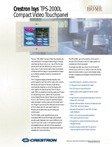
The 12 inch (30.1 cm) touch sensitive viewing screen is located on the front of the
TPS-5000L touchpanel, shown after this paragraph. The electronic hardware is
housed in a black metal enclosure. All audio, video, Ethernet, RS-232, and network
connections are made at the rear of the unit. The grill located on the front of the unit
conceals two speakers and a microphone.
4 • 12 Inch Lectern/Wall Mount Touchpanel: Crestron Isys™ TPS-5000L Operations Guide - DOC. 5783A

Crestron Isys™ TPS-5000L 12 Inch Lectern/Wall Mounted Touchpanel
NOTE: Video, RGB, and Ethernet connections are available after installing the
appropriate expansion card(s) into the TPS-5000L touchpanel.
TPS-5000L shown in black
Physical Views of the TPS-5000L Touchpanel (Front & Side)
13.43 in
(34.11 cm)
7.26 in
(18.44 cm)
11.04 in
(28.05 cm)
9.68 in
(24.59 cm)
2.70 in
(6.85 cm)
NOTE: For lectern cutout dimensions, refer to “Appendix B: Cutout Detail of
Supplied Template” on page 47.
Operations Guide - DOC. 5783A 12 Inch Lectern/Wall Mount Touchpanel: Crestron Isys™ TPS-5000L • 5

12 Inch Lectern/Wall Mounted Touchpanel Crestron Isys™ TPS-5000L
Physical Views of the TPS-5000L Touchpanel (Rear & Bottom)
3.25 in
(8.26 cm)
3.25 in
(8.26 cm)
4.45 in
(11.31 cm)
10.22 in
(25.97 cm)
12.49 in
(31.71 cm)
9.46 in
(24.03 cm)
Expansion Slots
The TPS-5000L’s functionality can be expanded by installing optional cards into the
expansion slots. Each card has a specific function and is sold separately. Installation
instructions are provided with each card. The available cards for the TPS-5000L are:
• TPS-ENETL – a 10/100 BaseT Ethernet card provides Ethernet
capability to the touchpanel.
• TPS-VIDL-1/TPS-VIDL-2 – a TV video digitizer card that allows
NTSC/PAL video to be played in a window on the touchpanel or full
screen. The TPS-VIDL-2 adds the capability of displaying two
composite video sources.
• TPS-XVGAL – a RGB digitizer that scan converts a computer source
up to 1600 x 1200 at 85 Hz (110 Hz @ 640 x 480) vertical rate to a
window on the touchpanel or full screen.
NOTE: The three cards are NOT interchangeable and can only be installed in their
dedicated expansion slots.
Memory
The TPS-5000L ships with 4MB of flash and 8MB of DRAM. Additional memory
by Crestron can be purchased separately and installed in the field. Refer to the latest
revision of the Flash Memory for TPS User Interfaces Installation Guide (Doc. 5927)
for an installation procedure.
6 • 12 Inch Lectern/Wall Mount Touchpanel: Crestron Isys™ TPS-5000L Operations Guide - DOC. 5783A

Crestron Isys™ TPS-5000L 12 Inch Lectern/Wall Mounted Touchpanel
Industry Compliance
As of the date of manufacture, the touchpanel have been tested and found to comply
with specifications for CE marking and standards per EMC and
Radiocommunications Compliance Labelling (N11785).
NOTE: This device complies with part 15 of the FCC rules. Operation is subject to
the following two conditions: (1) this device may not cause harmful interference,
and (2) this device must accept any interference received, including interference that
may cause undesired operation.
Setup
Network Wiring
NOTE: When installing network wiring, refer to the latest revision of the wiring
diagram(s) appropriate to your specific system configuration, available from the
Downloads | Product Manuals | Wiring Diagrams section of the Crestron website
(www.crestron.com).
When calculating the wire gauge for a particular Cresnet run, the length of the run
and the power factor of each Cresnet unit to be connected must be taken into
consideration. If Cresnet units are to be daisy-chained on the run, the power factor of
each network unit to be daisy-chained must be added together to determine the
power factor of the entire chain. The length of the run in feet and the power factor of
the run should be used in the following resistance equation to calculate the value on
the right side of the equation.
Resistance Equation
R = Resistance (refer to table below).
L = Length of run (or chain) in feet.
PF = Power factor of entire run (or chain).
R <
L x PF
40,000
Where:
The required wire gauge should be chosen such that the resistance value is less than
the value calculated in the resistance equation. Refer to the table after this paragraph.
Wire Gauge Values
RESISTANCE (R) WIRE GAUGE
4
16
6
18
10
20
15
22
13
Doubled CAT5
8.7
Tripled CAT5
Operations Guide - DOC. 5783A 12 Inch Lectern/Wall Mount Touchpanel: Crestron Isys™ TPS-5000L • 7

12 Inch Lectern/Wall Mounted Touchpanel Crestron Isys™ TPS-5000L
NOTE: All network wiring must consist of two twisted pairs. One twisted pair is
the +24V conductor and the GND conductor. The other twisted pair is the Y and Z
conductors.
NOTE: When daisy-chaining Cresnet units, strip the ends of the wires carefully to
avoid nicking the conductors. Twist together the ends of the wires that share a pin on
the network connector, and tin the twisted connection. Apply solder only to the ends
of the twisted wires. Avoid tinning too far up the wires or the end becomes brittle.
Insert the tinned connection into the Cresnet connector and tighten the retaining
screw. Repeat the procedure for the other three conductors.
NOTE: For larger networks (i.e., greater than 28 network devices), it may become
necessary to add a Cresnet Hub/Repeater (CNXHUB) to maintain signal quality
throughout the network. Also, for networks with lengthy cable runs, it may be
necessary to add a Hub/Repeater after only 20 devices.
Identity Code
Every equipment and user interface within the network requires a unique Cresnet
identity code (NET ID). These codes are recognized by a two-digit hexadecimal
number ranging from 03 to FE. Refer to “Interface Menu” on page 10 for
instructions on setting the unit's NET ID. The NET ID of the unit must match the
NET ID specified in the SIMPL Windows program. Refer to “Setting the Net ID in
Device Settings” on page 25 for information about changing the ID in a SIMPL
Windows program.
Configuring the Touchpanel
NOTE: The only connection required to configure the touchpanel is power. Refer to
“Hardware Hookup” on page 16 for details.
MAIN MENU
This menu can also be obtained via
digital reserved join number, 17242.
To configure the unit, it may be necessary to access a series of setup screens prior to
viewing run-time screens that are loaded into the touchpanel for normal operation.
The MAIN MENU for configuring the touchpanel appears when a finger is held to
the touchscreen as power is applied. Remove your finger when the message “SETUP
MODE” appears on the touchscreen.
NOTE: The SETUP MODE can also be accessed through the Viewport Utility if the
touchpanel is connected directly to a PC.
Upon entering SETUP MODE, the MAIN MENU, shown to the left, displays four
buttons: Touch Screen Calibration, Exit and Run Program, Setup, and
Diagnostics.
The Exit and Run Program button verifies that all of the setup information has
been saved to EEPROM and displays the main page that has been programmed into
your system. The remaining buttons on the MAIN MENU open other menus, which
are discussed in subsequent paragraphs.
8 • 12 Inch Lectern/Wall Mount Touchpanel: Crestron Isys™ TPS-5000L Operations Guide - DOC. 5783A

Crestron Isys™ TPS-5000L 12 Inch Lectern/Wall Mounted Touchpanel
Calibration Menu
CALIBRATION MENU
Calibration of the touchscreen is required if the active touch area of a button does
not coincide with the button's image. Select the Touch Screen Calibration
b
utton to
display the CALIBRATION MENU, shown to the left. The CALIBRATION MENU
offers the choice to initiate calibration with the Perform Calibration button or
return to the previous screen with the Return button. Choose an option by touching
the correct button.
If you proceed to calibrate the touchpanel, the screen displays the message "Touch
Upper Left" centered on the panel with a cross hair in the corner. Touch the cross
hair in the corner of the screen to initiate calibration. Another message, "Touch
Upper Right", appears with a cross hair in the correct corner. Touch the corner of the
screen. A final message, “Touch Lower Right”, appears with a cross hair in the
correct corner. Touch the corner of the screen to conclude calibration and return to
the MAIN MENU.
NOTE: When touching the screen during calibration, be as accurate as possible.
Use the tip of a capped pen or the eraser end of a pencil. To cancel calibration and
return to the CALIBRATION MENU without saving calibration data, create a
calibration error by touching the screen in an area that is opposite from the instructed
area.
Setup Menu
SETUP MENU
To access the SETUP MENU, shown to the left, press the Setup button from the
MAIN MENU. The SETUP MENU offers a series of buttons, which opens
additional menus and displays, which are detailed in subsequent paragraphs. Many
touchpanel options (i.e., standby timeout and brightness) are available directly from
the SETUP MENU and are explained in the following paragraphs. Other setup
parameters (i.e., interface, RS-232, audio, RGB, and video) use additional menus
and are detailed in subsequent paragraphs as well. After setup parameters have been
set, select the Return button to return to the MAIN MENU.
NOTE: The current CRESNET ID setting is displayed in the upper left corner of
the SETUP MENU.
NOTE: All touchpanel settings are automatically saved in non-volatile memory.
NOTE: The Ethernet, RGB, and Video buttons will only be displayed if the
respective TPS-ENETL, TPS-XVGAL or TPS-VIDL-1/2 cards are installed.
NOTE: If the TPS-VIDL-2 is installed, two video buttons will be displayed; “Video
1” and “Video 2”. Press the button for the respective video source.
The touchpanel display can be turned off (standby mode) when not in active use.
STANDBY TIMEOUT, located in the middle of the SETUP MENU, can turn off
the touchpanel when it is inactive for a specified time frame (minutes, shown as
XXX in the illustration). When the touchpanel is activated, the last screen to be
displayed reappears. Minutes can vary from 0 to 120, where 0 disables the timeout.
DOWN and UP buttons decrease and increase the timeout, respectively.
Screen brightness may need to be altered because of ambient light conditions or
personal preference. BRIGHTNESS, located in the lower left corner of the SETUP
Operations Guide - DOC. 5783A 12 Inch Lectern/Wall Mount Touchpanel: Crestron Isys™ TPS-5000L • 9

12 Inch Lectern/Wall Mounted Touchpanel Crestron Isys™ TPS-5000L
MENU, can change the brightness level of the display. The current brightness setting
is shown as a percentage in the SETUP MENU (e.g., 99% brightness is shown in the
illustration). Percentage can vary from 0% (low brightness) to 100% (full
brightness). DOWN and UP buttons decrease and increase the brightness,
respectively.
Interface Menu
INTERFACE MENU
The touchpanel communicates with a control system to activate commands or to
display feedback from components within the system. The communication interface
must be correctly specified or communication will not occur. To set communication
parameters select the Interface
b
utton located on the SETUP MENU and display the
INTERFACE MENU, shown to the left.
The Cresnet network identity number (CRESNET ID) is displayed on the
INTERFACE MENU. CRESNET ID is the two-digit hexadecimal number. The
hexadecimal number can range from 03 to FE and must correspond to the NET ID
set in the SIMPL Windows program of the Cresnet system. Matching IDs between
touchpanel and SIMPL Windows program is required if data is to be successfully
transferred. NET ID for the TPS-5000L is factory set to 03, and no two devices in
the same system can have the same ID.
Two buttons adjacent to the hexadecimal display, UP and DOWN, increase and
decrease the CRESNET ID by one, respectively.
The touchpanel usually communicates with a Cresnet system. Occasionally the
touchpanel can be used in a demo mode where it merely displays various menus, but
does not communicate with a Cresnet system. In demo mode, the directory buttons
change pages, but buttons requiring feedback do not work. Two side-by-side buttons
to the right of the CRESNET ID, Enable CRESNET II and Disable CRESNET II,
determine communication mode. Select Enable CRESNET II for normal Cresnet
communication mode and Disable CRESNET II to set the touchpanel into demo
mode. Text within the selected button changes color from black to red.
Communication mode is factory set to Enable CRESNET II.
It is possible to maintain touchpanel control (with the Enable Touch Screen button)
while communicating via RS-232 with the console or non-Crestron device.
Otherwise, choose Disable Touch Screen to discontinue touchpanel control. Text
within the selected button changes color from black to red.
There may be Ethernet devices (i.e. a control system) on the network that
communicates with the touchpanel via CIP (Cresnet Internet Protocol). Two buttons
centrally located on the Interface Menu determine if the touchpanel is capable of this
type of communication. Select Enable CIP to permit this protocol recognition and
Disable CIP to prohibit any CIP connection. CIP must be enabled for the touchpanel
to communicate with other Crestron Ethernet devices.
NOTE: The CIP control buttons will only be displayed when the TPS-ENETL is
properly installed.
NOTE: Refer to “Diagnostics Menu” on page 16 for instructions on enabling the
Ethernet card.
NOTE: If an Ethernet card is installed and enabled, and CIP control is disabled, the
touchpanel will not be able to communicate with other Crestron Ethernet devices, but
will be able to communicate with utilities such as Viewport via TCP/IP.
10 • 12 Inch Lectern/Wall Mount Touchpanel: Crestron Isys™ TPS-5000L Operations Guide - DOC. 5783A

Crestron Isys™ TPS-5000L 12 Inch Lectern/Wall Mounted Touchpanel
Select the Return button located on the INTERFACE MENU to accept the changes
and return to the SETUP MENU.
RS-232 Menu
RS-232 MENU
The touchpanel allows for five RS-232 communication methods:
• Console (i.e. loading programs)
• Control (i.e. non-Crestron device)
• Touch output (communication of touch coordinates to an external device)
• Mouse input (allows a mouse to control an external device as a “touch the
PC” device)
• External touch screen input.
Touch the communication option to select communication parameters and then
select Save and Return to save the RS-232 settings and return to the SETUP
MENU. For instructions on selecting the communication method, refer to “Appendix
C: Configuring the RS-232 Port for Use” on page 48.
Audio Menu
AUDIO MENU
The Audio button, located on the top row of the SETUP MENU, is used to display
the AUDIO MENU. Use this screen to activate sounds (recorded WAV files or line
level input from an external source), the microphone Automatic Gain Control
(AGC), and audible key clicks. This feature is a useful feedback tool or can enhance
a custom interface.
Volume (for WAV & line input) is controlled with the DOWN and UP buttons in
the first row. For example, the WAV File Volume value is shown as a red bar graph
and is controlled with the DOWN and UP buttons. Line and key click volume is
similarly adjusted.
Balance (for each audio type) is controlled with the LEFT and RIGHT buttons in
the third row. For example, the WAV File Balance value is shown as a red bar
graph and is controlled with the LEFT and RIGHT buttons. Line balance is
similarly adjusted.
The Play WAV File button appears beneath AUDIO MENU title block. Select this
button to adjust the volume and balance as a pre-loaded WAV file plays. WAV file
audio messages can provide that custom interface with a touchpanel, assuming this
feature is enabled. To enable this feature, verify that the WAV On button is active
(red text). An active WAV Off button disables the feature. Refer to "WAV File
Audio Messages" on page 29 for more information on WAV files.
Line level audio is possible only when enabled and the proper external connections
are made. Refer to "Hardware Hookup" on page 16 for information about the
AUDIO INPUT port. To enable this feature, verify that the Line On button is active
(red text). An active Line Off button disables the feature.
Confirmation of a button press on a touchpanel is acknowledged by an audible click
assuming this feature is enabled. To enable this feature, verify that the Key Click
On button is active (red text). An active Key Click Off button disables the feature.
NOTE: If key click is enabled on a touchpanel, each press of the touchpanel results
in an audible click. It may be desirable to conceal the key click sound for certain
buttons (e.g., if the button triggers playing of a WAV file). Using VT Pro-e, the
panel designer has the option to suppress the key click on a button-by-button basis
Operations Guide - DOC. 5783A 12 Inch Lectern/Wall Mount Touchpanel: Crestron Isys™ TPS-5000L • 11

12 Inch Lectern/Wall Mounted Touchpanel Crestron Isys™ TPS-5000L
from the "Button Properties" window.
It is possible to enable/disable all audio types (WAV, line, and key click) with the
press of a single button. The All Audio On and All Audio Off buttons allow for
global muting. Select the All Audio On button to enable audio; select the All Audio
Off button to disable audio.
The built-in microphone Automatic Gain Control (AGC) mode can be controlled
with two buttons on the AUDIO MENU: Mic Audio AGC On and Mic Audio
AGC Off.
NOTE: AGC is gain control and does not turn off the microphone.
Select the Default Settings button to restore all AUDIO MENU buttons and settings
to a factory-adjusted preset. Select the Return button, located at the lower right
corner of the AUDIO MENU, after audio parameters have been set.
Ethernet
NOTE: The Ethernet button is displayed on the SETUP MENU only if the
TPS-ENETL is properly installed.
NOTE: IP settings are necessary only if the TPS-ENETL is installed. Serially
connect a PC to the TPS-5000L via the RS-232 connector and refer to the details in
the latest revision of the TPS-ENETL (Doc. 6013).
Selection of the Ethernet button from the Setup Menu displays details such as the IP
Address, Subnet Mask, Def(ault) Router, IP Table, etc. For example, refer to a
sample display shown after this paragraph. The settings can only be viewed from this
screen. To enter commands to access/set all Ethernet configurations use the RS-232
connector and refer to the information in the TPS-ENETL Installation & Operations
Guide, as stated in the previous note.
Sample Display from Ethernet Button Press
RGB Menu
NOTE: The RGB button is displayed on the SETUP MENU only if the
TPS-XVGAL is properly installed. Selection of the RGB button opens the RGB
Menu from which the user can adjust RGB settings.
With a TPS-XVGAL installed, the TPS-5000L can display a computer-generated
video signal. The type of format must be selected carefully or the video may appear
12 • 12 Inch Lectern/Wall Mount Touchpanel: Crestron Isys™ TPS-5000L Operations Guide - DOC. 5783A

Crestron Isys™ TPS-5000L 12 Inch Lectern/Wall Mounted Touchpanel
unstable or noisy. Selecting the RGB button, located to the right on the top row of
the SETUP MENU, displays the RGB Menu, shown after this paragraph.
RGB Menu (Vertical Lines Portray RGB Sample)
The user has the option to manually select the incoming format or have the
touchpanel detect one automatically. On the rare occasion, the user may want to
choose the Manual Select button to force an incoming format. Otherwise, choose
the Auto Detect button to have the touchpanel automatically determine the format of
the input signal.
NOTE: Refer to the latest revision of the TPS-XVGAL Operations & Installation
Guide (Doc. 5945) for signal format specifications.
The characteristics of the input signal are displayed centrally on the right side of the
RGB Menu. For example, in the previous illustration, the input signal has a
resolution of 1024 x 768 with a frequency of 60.9 KHz (horizontal) and 76.1 Hz
(vertical).
While viewing the sample of the input signal, use the double arrow buttons to the left
and then the other set of double arrow buttons to position and compress/expand the
sample so that it fills the entire screen. Also, use the Phase Rev and Phase Fwd
buttons to adjust the timing of the sample. The Recenter button only needs to be
used if the sample disappears from the screen while making adjustments with the
double arrow buttons.
The touchpanel is capable of storing 16 VGA formats; the panel is factory set with
the presets empty. Select SAVE Menu to open the Preset Menu, as shown below. To
assign a format to a preset, complete the following steps:
Preset Menu (Vertical Lines Portray RGB Sample)
Operations Guide - DOC. 5783A 12 Inch Lectern/Wall Mount Touchpanel: Crestron Isys™ TPS-5000L • 13

12 Inch Lectern/Wall Mounted Touchpanel Crestron Isys™ TPS-5000L
1. Select a preset button (numbered 1 through 16). For the sake of this
procedure, select 11.
2. Select the Return button in the lower right corner of the Preset Menu
to display the RGB Menu.
3. While viewing the sample of the input signal, use the double arrow
buttons to the left and then the other set of double arrow buttons to
position and compress/expand the sample so that it fills the entire
screen.
NOTE: The Recenter button only needs to be used if the sample disappears from
the screen while making adjustments in step 3.
4. While viewing the sample of the input signal, use the Phase Rev and
Phase Fwd buttons to adjust the timing of the sample.
5. If visually satisfied with the sample at this point, select the Save Menu
button. Otherwise use the buttons on the screen to make additional
adjustments.
6. If necessary, select the More Controls button to show additional
controls for RGB. At any time, the Return button can be selected to
return to the Preset Menu.
7. If visually satisfied with the sample, select the Save Preset button to
store the values of the input into the preset assigned in step 1.
Otherwise repeat steps 3, 4, and 6 to make additional adjustments.
There are two buttons on the Preset Menu that influence the storage of format
presets. Use the Erase Selected Preset button to eliminate the stored format for the
highlighted preset. The Clear All Presets button eliminates the formats for all
presets. The touchpanel prompts the user for confirmation.
NOTE: If no presets are stored or the input does not closely match a stored preset,
the panel makes a 'best guess' for image settings.
Select the Return button, located at the lower right corner of the RGB Menu, after
RGB parameters have been set.
Video Menu
NOTE: The Video button is displayed on the Setup Menu only if the TPS-VIDL-1
is properly installed. If the TPS-VIDL-2 is installed, two Video buttons labeled
Video 1 and Video 2 will be displayed. Selection of a Video button opens the Video
Menu from which the user can adjust video settings.
The TPS-5000L can display video from up to four different composite video sources
connected to either the 6-pin connector or the BNC connectors. However, only two
composite video channels can be selected for viewing. Refer to the latest revision of
the TPS-VIDL-1/VIDL-2 Operations & Installation Guide (Doc. 6070) for details.
14 • 12 Inch Lectern/Wall Mount Touchpanel: Crestron Isys™ TPS-5000L Operations Guide - DOC. 5783A

Crestron Isys™ TPS-5000L 12 Inch Lectern/Wall Mounted Touchpanel
Video Setup (Horizontal Lines Portray Video Sample)
Use this screen to select one of the video inputs and adjust the brightness, contrast,
saturation, and hue, if necessary. The user has the option to force the video image to
a certain mode (i.e., composite video or S-video if using the TPS-VIDL-1 or
TPS-VIDL-2 in S-video configuration) or switch modes automatically after checking
the image for colors. Use either the TP Composite / BNC Composite or
TP S-Video / BNC S-Video buttons to manually control the mode. TP or BNC on
the selected button specifies the video input connector. TP corresponds to the twisted
pair connector (balanced video from a PVID, Room Box, etc.) and BNC corresponds
to the BNC connectors (unbalanced video from a VCR, DVD, etc.). Use the
appropriate Auto Detect button for automatic control. The text color of the selected
button is red rather than black.
NOTE: When configuring the TPS-VIDL-2, the Video 1 signal type can be
automatically detected as long as one signal is sent to the touchpanel.
NOTE: Up to four composite video feeds can be physically connected to a TPS-
VIDL-2 (two BNC feeds and two twisted-pair feeds). However, only two composite
video channels can be selected for viewing. Specify the connections to use by
selecting TP composite, TP S-Video, BNC Composite, or BNC S-Video for each
channel.
NOTE: A solid blue screen is displayed in the video window if a video signal is not
detected or is very weak. Verify that the video source is functioning and properly
connected. If the source is properly connected and functioning, a distribution
amplifier may need to be used.
Fast motion mode (if the Fast Motion button is selected) reduces motion artifacts
and should be used for most video sources. Still video mode (if the Still Video
button is selected) works best for still pictures. It has a maximum resolution and
reduces flicker. However, it suffers from motion artifacts. The text color of the
selected button is red rather than black.
Select the Soft button for soft mode video. In this mode, video filtering and noise
reduction can produce a better image from some sources. Alternatively, select the
Sharp button for sharp mode video. This mode provides maximum detail, but is
more susceptible to noise in source. The text color of the selected button is red rather
than black.
Operations Guide - DOC. 5783A 12 Inch Lectern/Wall Mount Touchpanel: Crestron Isys™ TPS-5000L • 15

12 Inch Lectern/Wall Mounted Touchpanel Crestron Isys™ TPS-5000L
Select the Return button, located at the lower right corner of the Video Menu, after
video parameters have been set.
Diagnostics Menu
DIAGNOSTICS MENU
The Diagnostics button from the MAIN MENU contains controls for enabling an
Ethernet card (if installed) and diagnostic tools. The diagnostic tools should only be
used under supervision from a Crestron customer service representative during
telephone support. The options available from the DIAGNOSTICS MENU, shown
to the left, are numeric in nature and their interpretation is beyond the scope of this
manual.
NOTE: If the Disable Ethernet button is selected, the touchpanel will not
communicate via TCP/IP or Cresnet Internet Protocol (CIP). Select “Enable
Ethernet” to enable the Ethernet card.
NOTE: The “About…” button will display a screen indicating the current version
of firmware residing on the touchpanel.
Hardware Hookup
Make the necessary connections as called out in the illustration that follows this
paragraph. Refer to “Network Wiring” on page 7 before attaching the 4-pin
connector. Apply power after all connections have been made.
CAUTION: Do not apply excessive pressure to the touchscreen display during
handling (mounting/installation). Doing so can crack the screen and damage the
touchpanel.
Hardware Connections for the TPS-5000L (Back of the Unit is Shown)
NTSC/PAL INPUT
RS-232
AUDIO IN
NET
MIC OUT
YC
-++
S
-
S
RGB INPUT
COMP
AUDIO INPUT
This 6-position, mini- connector provides line level, balanced and unbalanced audio
input. The pinouts are shown in the tables after this paragraph.
16 • 12 Inch Lectern/Wall Mount Touchpanel: Crestron Isys™ TPS-5000L Operations Guide - DOC. 5783A
/