Ferm MMM1002 - MM 940 Owner's manual

Type
Owner's manual

This manual is also suitable for

1. TECHNICAL DATA
Product: Ferm Digital Multimeter
Type MM-940 Art. no. 185940
Ferm b.v. Genemuiden, Netherlands
3 1/2 Digit Liquid Crystal Display (max. readout: 1999)
Operation temperature: 0 .... 40°C (rel. humidity <75%)
Readout frequency: 2-3 seconds
Max. "Common mode" voltage: 500VDC or AC rms.
Storing temperature: -10 .... +50°C
The multimeter operates on a 9V battery of type
6LR62 or MN 1604.
"Battery LOW" indication: ' ' is lit.
Calibration: Accuracy will be guaranteed for a period of
1 year, at 23°C +/-5°C and a relative humidity of <75%.
READ THIS USER'S MANUAL CAREFULLY!
2. USAGE
Your multimeter can be used to perform measure-
ments of direct voltage (VDC), direct current (ADC),
alternating voltage (VAC), alternating current (AAC)
resistance (, Ohm) and diodes- and continuity test
and battery check.
3. KNOW YOUR PRODUCT
Read this user's manual carefully and pay attention to
the safety rules in particular, before you put your mul-
timeter into use. Maintain your multimeter according
to the instructions, to keep it in good shape. Do not
use your multimeter, until you really understand the
operation procedures. Keep this manual in a safe
place, together with the other documentation of your
device.
4. GENERAL SAFETY RULES
Your device has been developed with the greatest
care for safety. Any modification or extension of the
design can undo the safety.The guarantee can also be
cancelled for that reason.
Keep your working area neat and tidy:
- An untidy working environment can cause acci-
dents
- Provide sufficient lighting in your working environ-
ment
Be aware of the impact of your working area
Never use your multimeter in a moist or wet area.
Never leave it in the rain.
Keep children away
Never let other persons use your multimeter.
Keep them out of the working area.
Store your tools in a safe place
Keep your multimeter in a dry place, if you do not
use it.
Never overload your multimeter
You will work better and safer within the indicated
power range. The guarantee will not cover damage
due to overload.
Never use the measuring cord in the wrong way
Never carry your device, holding it with the
measuring cord. Do not pull the cord to remove
the plug from your multimeter. Always pull the
plug itself.
Maintain your multimeter carefully
Keep your multimeter clean, for better and safer
performances. Keep it dry and far from oil and grease.
Remove the measuring plug from your multi-
meter
If you do not use your multimeter.
Check your tools for damage
- Try the safety facilities or damaged parts carefully
on their excellent and purposive performance,
every time before you use your device.
- Check if all conditions have been met, which may
influence the performance of your device.
5. SPECIAL SAFETY RULES
1. WARNING! Measuring high voltages or cur-
rents can endanger your life. Never touch the bare
parts of the measuring cords, when you measure
voltages higher than 40 Volt or currents over 20
mA.
2. Your multimeter is a measuring instrument. Never
hit or drop it.
3. Turn the switch to the OFF-position to save the
battery, when you do not use your multimeter.
4. Keep your device far from high humidity or high
temperatures.
5. Keep your multimeter far from strong magnetic
fields.
6. Remove the battery to prevent leakage, when you
intend to put your multimeter out of use for a long
time.
7. Remove the cords immediately, when you smell
+
UK
English
2 Ferm
9V
Type 6LR61 or
Type MN 1604
Ferm 31
R
MM-940
C
B
00.0
F
D
E
A
Fig.1
2. µÁ¿ÏÙ ÚÒÙ· ÙÔ ›Ûˆ ̤ÚÔ˜ ÙÔ˘ ÔÏ˘Ì¤ÙÚÔ˘ Û·˜,
ÍÂÛÊ›ÁÁÔÓÙ·˜ ÙȘ ‚›‰Â˜.
™∏ª∂πø™∏: £¤ÛÙ ÂÎÙfi˜ ÙÔ ÔχÌÂÙÚÔ Î·È
‚Á¿ÏÙ ÙÔ˘˜ ·ÁˆÁÔ‡˜ ̤ÙÚËÛ˘ ÚÈÓ Ó· ·ÓÔ›ÍÂÙÂ
ÙÔ Î¿Ï˘ÌÌ· ÙÔ˘ ÔÏ˘Ì¤ÙÚÔ˘ Û·˜.
3. ∏ η̤ÓË ·ÛÊ¿ÏÂÈ· Ú¤ÂÈ Ó· ·Ê·ÈÚÂı› Î·È Ó·
·ÓÙÈηٷÛÙ·ı› Ì ·ÛÊ¿ÏÂÈ· Ù˘ ›‰È·˜ ¤ÓÙ·Û˘ ηÈ
Ù·¯‡ÙËÙ·˜ (0,2A/250V)
AÓÙÈηٿÛÙ·ÛË Ù˘ Ì·Ù·Ú›·˜
1. ∏ ÔıfiÓË ı· ‰Â›¯ÓÂÈ ¤Ó· ۇ̂ÔÏÔ Ì·Ù·Ú›·˜ fiÙ·Ó Ë
Ì·Ù·Ú›· Â›Ó·È Û¯Â‰fiÓ ¿‰ÂÈ·.
2. °˘Ú›ÛÙ ÙÔ ÂÚÈÛÙÚÂÊfiÌÂÓÔ ÎÔ˘Ì› ÛÙË ı¤ÛË OFF.
3. µÁ¿ÏÙ ÚÒÙ· ÙÔ ›Ûˆ ̤ÚÔ˜ ÙÔ˘ ÔÏ˘Ì¤ÙÚÔ˘ Û·˜,
Í‚ȉÒÓÔÓÙ·˜ ÙȘ ‚›‰Â˜.
™∏ª∂πø™∏: £¤ÛÙ ÂÎÙfi˜ ÙÔ ÔχÌÂÙÚÔ Î·È
‚Á¿ÏÙ ÙÔ˘˜ ·ÁˆÁÔ‡˜ ̤ÙÚËÛ˘ ÚÈÓ Ó· ·ÓÔ›ÍÂÙÂ
ÙÔ Î¿Ï˘ÌÌ· ÙÔ˘ ÔÏ˘Ì¤ÙÚÔ˘.
4. ∆ÒÚ·, ·ÓÙÈηٷÛÙ‹ÛÙ ÙË Ì·Ù·Ú›· 9V ÌÂ
ηÈÓÔ‡ÚÁÈ·.
30 Ferm
stinking insulation.
8. Use your multimeter, only if it is closed.
6. GUARANTEE CONDITIONS
1. Ferm has thoroughly proved this product and vou-
ches for the good quality of manufacturing and
material. Ferm grants a 12 MONTHS guarantee,
from the date of purchase, covering every material
and production fault, that might occur. Any other
kind of claim on compensation, direct or indirect,
to persons and/or materials, will be rejected.
2. First, consult your Ferm dealer. Usually, your
dealer will be able to eliminate the problem or the
failure.
3. The term of guarantee cannot be extended, by
repairing or replacing parts within the guarantee
period.
4. Normal wearing will not be covered by the guar-
antee; e.g. switches are not covered and also
damage due to out-of-range measurements.
5. YOUR RIGHT ON GUARANTEE WILL
ONLY BE VALID IF:
-a proof of the date of purchase can be shown, in
the form of a PURCHASE RECEIPT;
- the associated guarantee certificate has been
signed and filled in completely;
- neither third parties have carried out any
repair or modification on the device, nor any
non-original part has been assembled;
- the device has been treated, according to the
operation instructions;
- there are no circumstances beyond our control.
6. The guarantee conditions will apply in conjunction
with our terms of delivery and conditions of sale.
7. The transport costs of the device to be repaired
will come to the account of the buyer. Badly wrap-
ped articles will be rejected.
8. The guarantee certificate is enclosed in the back of
this manual.
7. ENVIRONMENTAL PROTECTION
Regaining of resources is better than wasting them!
Your device must be delivered in a solid wrapping, to
avoid damage due to transport. This wrapping has
been made of recyclable material, such as paper, card-
board and wood. We recommend to recycle the
wrapping as much as possible.
Your multimeter contains a battery.
Never waste this battery when it got
empty, but hand it in as "Small Che-
mical Waste".
For replacement of the battery, refer to chapter 13
"Replacing the battery".
8. FERM AFTER-SALES SERVICE
Keep the original wrapping. Using this original wrap-
ping will minimize the probability of transport damage,
if your device still has to be transported. In case of a
guarantee claim, your device must be presented in the
strongest possible wrapping, preferably the original
one. Each Ferm product has been proved with utmost
accuracy, before leaving the factory. Consult your
Ferm dealer, if your device still gets out of order.
9. BEFORE USING YOUR DEVICE
1. Set the turning knob to the highest range, if you do
not know the voltage and/or current to be meas-
ured. Adjust the turning knob one measuring-ran-
ge lower and so on, if the accuracy is not enough.
2. Set the turning knob to OFF, if you do not use your
device.
3. The difference between the measurement of vol-
tage and current is based on the circuit of your
multimeter: Parallel for voltage and in series for
current measurements. In the latter case, a con-
ductor will have to be interrupted.
4. Never connect a source or charge to your multi-
meter, with the FUNCTION-switch in or
position.
5. Never connect a voltage over 1000 VDC or 700
VAC rms to your multimeter.
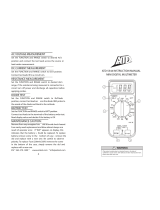
10. OPERATION
SEE FIG. 1
A. LCD display. Large 3 1/2 digit display, with a read-
out upto 1999. Indications for decimal point, pola-
rity, overload and empty battery.
B. Range switch. Rotary switch to set the range.
C. 20A. Positive connector for measuring currents
above 200 mA upto 20A.
D. mA. Positive connector for the measurement of
currents upto 200 mA.
E. COM. Negative connector
F. V/. Positive connector for voltage and resistance
measurements.
11. MEASURING
11.1 Measuring direct voltage (VDC)
1. Connect the BLACK cord to the "COM"-con-
nector and the RED cord to the V/-connector.
2. Set the FUNCTION-switch to the desired
“V position and put the cords over the
respective source or charge. Mind the correct
polarity (red is +, black is -), otherwise the display
will show a minus-sign before the value.
3. Readout the value in Volt.
Ferm 3
ÌfiÓÔ fiÙ·Ó ÂÌÊ·Ó›˙ÂÙ·È Ô ·ÚÈıÌfi˜ "1". ™ÙËÓ
ÂÚ›ÙˆÛË ·˘Ù‹, Ë ÙÈÌ‹ Â›Ó·È ÂÎÙfi˜ ÂÚÈÔ¯‹˜.
3. ∏ ̤ÁÈÛÙË Ù¿ÛË ÂÈÛfi‰Ô˘ Â›Ó·È 1000V. ¢ÂÓ ÌÔÚÔ‡Ó
Ó· ÌÂÙÚËıÔ‡Ó ˘„ËÏfiÙÂÚ˜ Ù¿ÛÂȘ.
4. ¶ÚÔÛ¤¯ÂÙ ¿Ú· Ôχ fiÙ·Ó ÌÂÙÚ¿Ù ˘„ËϤ˜ Ù¿ÛÂȘ.
11.2 ª¤ÙÚËÛË ÂÓ·ÏÏ·ÛÛfiÌÂÓ˘ Ù¿Û˘ (VAC)
1. µ¿ÏÙ ÙÔÓ ªAÀƒ√ ·ÁˆÁfi ÛÙÔÓ Û˘Ó‰ÂÙ‹Ú· “COM”
Î·È ÙÔÓ ∫√∫∫π¡√ ÛÙÔÓ Û˘Ó‰ÂÙ‹Ú· “V/ø”.
2. ƒ˘ıÌ›ÛÙ ÙÔ ÎÔ˘Ì› FUNCTION ÛÙËÓ ÂÈı˘ÌËÙ‹
ı¤ÛË “V~” Î·È Û˘Ó‰¤ÛÙ ÙÔ˘˜ ·ÁˆÁÔ‡˜ ÛÙËÓ ËÁ‹ ‹
ÙÔ ÊÔÚÙ›Ô Ô˘ ÚfiÎÂÈÙ·È Ó· ÌÂÙÚ‹ÛÂÙÂ. ∏
ÔÏÈÎfiÙËÙ· ÙˆÓ ·Î›‰ˆÓ ̤ÙÚËÛ˘ ‰ÂÓ ¤¯ÂÈ ÛËÌ·Û›·.
3. ¢È·‚¿ÛÙ ÙËÓ ÙÈÌ‹ Û Volt.
¶∂ƒπ√Ã∏ ∞∫ƒπµ∂π∞ ∞¡∞§À™∏
AÓÙ›ÛÙ·ÛË ÂÈÛfi‰Ô˘: 10 ªø
¶ÂÚÈÔ¯‹ Û˘¯ÓfiÙËÙ·˜: 40 .... 400 Hz
AÛÊ¿ÏÂÈ· ˘ÂÚÊfiÚÙÈÛ˘: AC 750 rms ‹ DC 1000V ̤ÁÈÛÙÔ.
(™˘Ó¯‹˜ Û fiϘ ÙȘ ÂÚÈÔ¯¤˜)
ŒÓ‰ÂÈÍË: ª¤ÛË ÙÈÌ‹ (rms ËÌÈÙÔÓÔÂȉԇ˜ Û¯‹Ì·ÙÔ˜)
™ËÌ.:
1. ∂¿Ó Ë ÂÚÈÔ¯‹ Ù¿Û˘ Â›Ó·È ¿ÁÓˆÛÙË, Ú˘ıÌ›ÛÙ ÙÔ
‰È·ÎfiÙË FUNCTION ÛÙË Ì¤ÁÈÛÙË ÙÈÌ‹ Î·È ÌÂÈÒÛÙÂ
ÙËÓ ÛÙ·‰È·Î¿, ·Ó ¯ÚÂÈ·ÛÙ›.
2. ƒ˘ıÌ›ÛÙ ÙÔ ‰È·ÎfiÙË FUNCTION Û ÌÂÁ·Ï‡ÙÂÚË
ÙÈÌ‹ ÌfiÓÔ fiÙ·Ó ÂÈÎÔÓ›˙ÂÙ·È ÛÙËÓ ÔıfiÓË Ô ·ÚÈıÌfi˜ "1".
™ÙËÓ ÂÚ›ÙˆÛË ·˘Ù‹, Ë ÙÈÌ‹ Â›Ó·È ÂÎÙfi˜ ÂÚÈÔ¯‹˜.
3. ∏ ̤ÁÈÛÙË ÙÈÌ‹ ÂÈÛfi‰Ô˘ Â›Ó·È 750 V. À„ËÏfiÙÂÚ˜
Ù¿ÛÂȘ ‰ÂÓ ÌÔÚÔ‡Ó Ó· ÌÂÙÚËıÔ‡Ó.
4. ¶ÚÔÛ¤¯ÂÙ ¿Ú· Ôχ fiÙ·Ó ÌÂÙÚ¿Ù ˘„ËϤ˜ Ù¿ÛÂȘ.
11.3 ª¤ÙÚËÛË Û˘Ó¯ԇ˜ Ú‡̷ÙÔ˜ (ADC)
1. ™˘Ó‰¤ÛÙ ÙÔÓ ªAÀƒ√ ·ÁˆÁfi ÛÙÔÓ Û˘Ó‰ÂÙ‹Ú·
“COM”. ™˘Ó‰¤ÛÙ ÙÔÓ ∫√∫∫π¡√ ·ÁˆÁfi ÛÙÔÓ
Û˘Ó‰ÂÙ‹Ú· “mA” ÁÈ· ̤ÙÚËÛË Ì¤¯ÚÈ 200 mA.
™˘Ó‰¤ÛÙ ÙÔ ∫√∫∫π¡√ ·ÁˆÁfi ÛÙÔ ÛËÌÂ›Ô “A” ÁÈ·
̤ÙÚËÛË Û ˘„ËÏfiÙÂÚË ÂÚÈÔ¯‹ ¤ÓÙ·Û˘, ̤¯ÚÈ 20A.
¶∂ƒπ√Ã∏ ∞∫ƒπµ∂π∞ ∞¡∞§À™∏
¶ÚÔÛÙ·Û›· ˘ÂÚÊfiÚÙÈÛ˘: ·ÛÊ¿ÏÂÈ· 0,2/250 V, Ë ÂÚÈÔ¯‹ 20A
‰ÂÓ ¤¯ÂÈ ·ÛÊ¿ÏÂÈ·.
2. ƒ˘ıÌ›ÛÙ ÙÔ ‰È·ÎfiÙË FUNCTION ÛÙËÓ ÂÈı˘ÌËÙ‹
ı¤ÛË “A Î·È Û˘Ó‰¤ÛÙ ÙÔ˘˜ ·ÁˆÁÔ‡˜ ÂÓ ÛÂÈÚ¿ ÌÂ
ÙÔ ·ÓÙ›ÛÙÔÈ¯Ô ÊÔÚÙ›Ô. ¶ÚÔÛ¤ÍÙ ÙË ÛˆÛÙ‹ ÔÏÈÎfiÙËÙ·
(ÙÔ ÎfiÎÎÈÓÔ Â›Ó·È + Î·È ÙÔ Ì·‡ÚÔ Â›Ó·È -) ÁÈ·Ù›
‰È·ÊÔÚÂÙÈο Ë ÔıfiÓË ı· ÚÔÛı¤ÛÂÈ ¤Ó· ÛËÌÂ›Ô ÏËÓ
ÛÙËÓ ÙÈÌ‹. ∏ ÔÏÈÎfiÙËÙ· ÙÔ˘ ∫√∫∫π¡√À ·ÁˆÁÔ‡ ı·
ÂÌÊ·ÓÈÛÙ› Ù·˘Ùfi¯ÚÔÓ· Ì ÙËÓ ÙÈÌ‹ Ù˘ ¤ÓÙ·Û˘.
3. ¢È·‚¿ÛÙ ÙËÓ ÙÈÌ‹ Û (milli) Ampere.
™ËÌ.:
1. AÓ ‰ÂÓ Í¤ÚÂÙ ÙË ÛˆÛÙ‹ ÂÚÈÔ¯‹, Ú˘ıÌ›ÛÙ ÙÔ
‰È·ÎfiÙË FUNCTION ÛÙË Ì¤ÁÈÛÙË ÙÈÌ‹ Î·È ÌÂÈÒÛÙÂ
ÙËÓ ÛÙ·‰È·Î¿, ·Ó ¯ÚÂÈ·ÛÙ›.
2. ƒ˘ıÌ›ÛÙ ÙÔ ‰È·ÎfiÙË FUNCTION Û ˘„ËÏfiÙÂÚË
ÙÈÌ‹ fiÙ·Ó ÂÈÎÔÓ›˙ÂÙ·È ÌfiÓÔ Ô ·ÚÈıÌfi˜ "1". ™ÙËÓ
ÂÚ›ÙˆÛË ·˘Ù‹, Ë ÙÈÌ‹ Â›Ó·È ÂÎÙfi˜ ÂÚÈÔ¯‹˜.
3. ∏ ÂÚÈÔ¯‹ 20A ‰ÂÓ ÚÔÛٷهÂÙ·È Ì ·ÛÊ¿ÏÂÈ·.
ªËÓ Î¿ÓÂÙ ÔÙ¤ ̤ÙÚËÛË Â› ÂÚÈÛÛfiÙÂÚÔ ·fi
10 ‰Â˘ÙÂÚfiÏÂÙ·.
11.4 ª¤ÙÚËÛË ÂÓ·ÏÏ·ÛÛfiÌÂÓÔ˘ Ú‡̷ÙÔ˜ (AAC)
1. ™˘Ó‰¤ÛÙ ÙÔÓ ªAÀƒ√ ·ÁˆÁfi ÛÙÔÓ Û˘Ó‰ÂÙ‹Ú·
“COM”. ™˘Ó‰¤ÛÙ ÙÔÓ ∫√∫∫π¡√ ·ÁˆÁfi ÛÙÔÓ
Û˘Ó‰ÂÙ‹Ú· “mA” ÁÈ· ̤ÙÚËÛË Ì¤¯ÚÈ 200 mA.
™˘Ó‰¤ÛÙ ÙÔÓ ∫√∫∫π¡√ ·ÁˆÁfi ÛÙÔ ÛËÌÂ›Ô “A” ÁÈ·
̤ÙÚËÛË Û ˘„ËÏfiÙÂÚË ÂÚÈÔ¯‹ ¤ÓÙ·Û˘, ̤¯ÚÈ 20A.
2. ƒ˘ıÌ›ÛÙ ÙÔ ‰È·ÎfiÙË FUNCTION ÛÙËÓ ÂÈı˘ÌËÙ‹
ı¤ÛË “A~” Î·È Û˘Ó‰¤ÛÙ ÙÔ˘˜ ·ÁˆÁÔ‡˜ ÂÓ ÛÂÈÚ¿ ÌÂ
ÙËÓ ·ÓÙ›ÛÙÔÈ¯Ë ËÁ‹ ‹ ÊÔÚÙ›Ô. ¶ÚÔÛ¤ÍÙ ÙË ÛˆÛÙ‹
ÔÏÈÎfiÙËÙ· (ÙÔ ÎfiÎÎÈÓÔ Â›Ó·È + Î·È ÙÔ Ì·‡ÚÔ Â›Ó·È -)
ÁÈ·Ù› ‰È·ÊÔÚÂÙÈο Ë ÔıfiÓË ı· ÚÔÛı¤ÛÂÈ ¤Ó· ÛËÌ›Ô
ÏËÓ ÛÙËÓ ÙÈÌ‹. ∏ ÔÏÈÎfiÙËÙ· ÙÔ˘ ∫√∫∫π¡√À
·ÁˆÁÔ‡ ı· ÂÌÊ·ÓÈÛÙ› Ù·˘Ùfi¯ÚÔÓ· Ì ÙËÓ ÙÈÌ‹ Ù˘
¤ÓÙ·Û˘.
3. ¢È·‚¿ÛÙ ÙËÓ ÙÈÌ‹ Û (milli) Ampere.
¶∂ƒπ√Ã∏ ∞∫ƒπµ∂π∞ ∞¡∞§À™∏
¶ÚÔÛÙ·Û›· ˘ÂÚÊfiÚÙÈÛ˘: ·ÛÊ¿ÏÂÈ· 0,2/250 V, Ë ÂÚÈÔ¯‹ 20A
‰ÂÓ ¤¯ÂÈ ·ÛÊ¿ÏÂÈ·.
¶ÂÚÈÔ¯‹ Û˘¯ÓfiÙËÙ·˜: 40... 400 Hz
ŒÓ‰ÂÈÍË: ̤ÛË ÙÈÌ‹ (rms ËÌÈÙÔÓÔÂȉԇ˜ Û¯‹Ì·ÙÔ˜)
™ËÌ.:
1. AÓ ‰ÂÓ Í¤ÚÂÙ ÙË ÛˆÛÙ‹ ÂÚÈÔ¯‹, Ú˘ıÌ›ÛÙ ÙÔ
‰È·ÎfiÙË FUNCTION ÛÙË Ì¤ÁÈÛÙË ÙÈÌ‹ Î·È ÌÂÈÒÛÙÂ
ÙËÓ ÛÙ·‰È·Î¿, ·Ó ¯ÚÂÈ·ÛÙ›.
2. ƒ˘ıÌ›ÛÙ ÙÔ ‰È·ÎfiÙË FUNCTION Û ˘„ËÏfiÙÂÚË
ÙÈÌ‹ fiÙ·Ó ÂÈÎÔÓ›˙ÂÙ·È ÌfiÓÔ Ô ·ÚÈıÌfi˜ "1". ™ÙËÓ
ÂÚ›ÙˆÛË ·˘Ù‹, Ë ÙÈÌ‹ Â›Ó·È ÂÎÙfi˜ ÂÚÈÔ¯‹˜.
3. ∏ ÂÚÈÔ¯‹ 20A ‰ÂÓ ÚÔÛٷهÂÙ·È Ì ·ÛÊ¿ÏÂÈ·.
ªËÓ Î¿ÓÂÙ ÔÙ¤ ̤ÙÚËÛË Â› ÂÚÈÛÛfiÙÂÚÔ ·fi
10 ‰Â˘ÙÂÚfiÏÂÙ·.
11.5 ª¤ÙÚËÛË ·ÓÙ›ÛÙ·Û˘ (ø OHM)
1. µ¿ÏÙ ÙÔÓ ªAÀƒ√ ·ÁˆÁfi ÛÙÔÓ Û˘Ó‰ÂÙ‹Ú· “COM”
Î·È ÙÔÓ ∫√∫∫π¡√ ÛÙÔÓ “V/ø”. (™ËÌ. ∏ ÔÏÈÎfiÙËÙ·
ÙÔ˘ ÎfiÎÎÈÓÔ˘ ÎÔÚ‰ÔÓÈÔ‡ Â›Ó·È "+").
2. ƒ˘ıÌ›ÛÙ ÙÔ ÎÔ˘Ì› FUNCTION ÛÙËÓ ÂÈı˘ÌËÙ‹
ÂÚÈÔ¯‹ “ø”.
3. ™˘Ó‰¤ÛÙ ÙȘ ·Î›‰Â˜ ̤ÙÚËÛ˘ ÛÙÔ ·ÓÙ›ÛÙÔȯÔ
ÛÙÔȯ›Ô. ¶ÚÔÛ¤ÍÙ ӷ ÌËÓ Â›Ó·È Û˘Ó‰Â‰Â̤ÓÔ ÙÔ
± 1,2% of rdg ± 3 digits
± 1,8% of rdg ± 3 digits
2mA
20mA
200mA
1µA
10µA
100µA
± 3% of rdg ± 7 digits20A 10mA
± 0,8% of rdg ± 1 digit
± 1,2% of rdg ± 1 digit
2mA
20mA
200mA
1µA
10µA
100µA
± 2% of rdg ± 5 digit20A 10mA
± 0,8% of rdg ± 3 digits
2V
20V
200V
1mV
10mV
100mV
750V 1V± 1,2% of rdg ± 3 digits
28 Ferm
2. Set the FUNCTION-switch to the desired “A
position and connect the cords in series to the
respective source or charge. Mind the right polari-
ty (red is + and black is -), otherwise the display will
add a minus-sign to the value. The polarity of the
RED cord will be shown, simultaneously with the
value of the current.
3. Readout the value in (milli) Ampere.
NB:
1. In case you do not know the current range, set the
FUNCTION-switch to the highest range and turn
it down gradually, if necessary.
2. Set the FUNCTION-switch to a higher range,
when only the figure "1" is displayed. In this case,
the value is out of range.
3. The 20A range is not protected with a fuse.
Never measure for more than 10 seconds.
11.5 Measuring resistance ( OHM)
1. Put the BLACK cord on the “COM” connector
and the RED one on “V/. (NB. The polarity of
the red cord is "+").
2. Set the FUNCTION knob to the desired -
range.
3. Connect the measuring pins to the respective
component. Take care that the component is not
connected to other components and do not touch
the points of the measuring pins, in order to pre-
vent inaccuracy of the resistance value.
4. Readout the value in (Ohm).
5. Current from the internal battery will be used, for
the measurement of resistance's. The electricity
consumption will vary with the range you have set.
RANGE ACCURACY RESOLUT.
Overload security: 250 VDC or AC rms. If less than 15 seconds.
NB:
1. "1" will be shown on the display, in case the meas-
ured resistance value exceeds the maximum value
of the selected range. Select a higher range. It can
take a few seconds for the meter to stabilize with a
resistance of about 1 M or higher. This is normal
when measuring high resistance's.
2. If the input is not connected, e.g. for an interrupted
circuit, the figure "1"will be shown on the display,
to indicate that the value is out of range.
3. In case the respective resistance is connected
to a circuit: Switch off the voltage and take
care that every condensator has been fully dis-
charged, before starting the measurement.
11.6 Measuring diodes
1. Connect the BLACK cord to the “COM”-con-
nector and the RED one to the “V/-connec-
tor. (NB. The polarity of the red cord is "+")
2. Set the FUNCTION-switch to the -range
and connect the measuring pins to the respective
diode. When measuring, the polarity of the measu-
ring pins will determine whether the diodes or
transistors are measured in the forward or rever-
se direction. The value shown on the display, will
be the voltage drop over the diode in the forward
direction.
- The test current will be 0.8 mA
- "1" will be shown on the display, when the
measuring cords are not or wrongly (= in
reverse direction) connected to the diode.
11.7 Continuity test
1. Put the BLACK cord to the “COM”-connector
and the RED one to the “V/ (NB. The polarity
of the red cord is "+")
2. Set the FUNCTION-switch to the -range and
connect the measuring pins to the respective circuit.
3. In case the resistance is less than 50, the buzzer
will sound.
11.8 Battery check
1. Connect the BLACK cord to the "COM" con-
nector and the RED one to the "V/" (NB. The
polarity of the red cord is "+")
2. Set the FUNCTION-switch to the desired
“BATT”-position and put the measuring pins on
the battery.
3. Readout the battery voltage.
RANGE ACCURACY RESOLUT.
Overload protection: 1.5 V range: 0.2 A/250V fuse
9 Volt range: 250V DC or ACRms.
12. MAINTENANCE
NOTE: Always remove the battery from your multi-
meter, when maintaining and cleaning. Never use
water or any other kind of fluid to clean your device.
Keep the measuring cords of your multimeter clean.
Some cleansing agents or solvents (petrol, thinner)
can affect or solve the plastic parts. These products
1,5 V
9 V
100 mA
6 mA± 0,8% of rdg ± 1 digit
± 0,8% of rdg ± 1 digit
200
2K
20K
200K
2M
20M
0,1
1
10
100
1k
10k
± 0,8% of rdg ± 1 digit
± 1% of rdg ± 2 digits
± 0,8% of rdg ± 3 digits
Ferm 5
  • Page 1 1
  • Page 2 2
  • Page 3 3
  • Page 4 4
  • Page 5 5
  • Page 6 6
  • Page 7 7
  • Page 8 8
  • Page 9 9
  • Page 10 10
  • Page 11 11
  • Page 12 12
  • Page 13 13
  • Page 14 14
  • Page 15 15
  • Page 16 16

Ferm MMM1002 - MM 940 Owner's manual

Type
Owner's manual
This manual is also suitable for

Ask a question and I''ll find the answer in the document

Finding information in a document is now easier with AI