Page is loading ...

1. Overview
This multimeter is characterized by a compact rugged construction with protective
holster and stand. The LCD Screen with 27mm display gives clear readings even
in low light when the backlight can be switched on. Features include dual slope
A/D
converter using C-MOS technology for auto-zeroing, polarity selection and
over-range indication. Full overload protection is provided.
Before use you will need to fit a 9V PP3 battery (not supplied) in the compartment
located on the back of the meter. To open the compartment remove the cross
headed screw from the lid and lever open, clip the terminal studs over the battery
terminal caps, close the compartment lid and screw tightly shut.
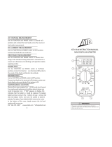
2. Panel Layout
1) LCD Display 27mm
2) POWER Switch: Boot Up / Shutdown
3) Data-hold Switch (HOLD): Pressing this button, the meter enters the auto data hold
mode and “HOLD” is displayed on the LCD.
4) Back Light Button Switch: Pressing the button turns the backlight on,
pressing it again turns it off.
5) Function switch indicator lamp
6) hFE Input Socket
7) Rotary Switch: use this switch to select functions and ranges
8) Mechanical blocki
ng system.
9) V/Ω
InputSocket,20AInputSocket,mAInputSocket&COMInputSocket
SPECIFICATIONS
3.1
GENERAL CHARACTERISTICS
3.1.1 3 ½ digit big LCD max. Indication 1999.
3.1.2 Auto-Zero&Auto-Polarity.
31.3 Overrange: indication of “1” or “-1”.
3.1.4 Low battery indication: “
”
3.1.5 Power supply: 9V Zinc-carbon battery.
3.1.6 Safetystandards:ThemetercomplieswithIEC1010DoubleInsulation,
Pollution Degree 2, overvoltage Category II.
3.1.7 Protective terminal socket covers prevent operational mistakes
3.1.8 Optimum operating temperature for accuracy: 23ºC±5ºC
3.1.9 Temperaturerange:Operating:0ºCto40ºCStorage:-20ºCto60ºC
3.1.10Humidityrange:
Operating:max75%RHStorage:max80%RH
3.1.11Size:190mmx88.5mmx27.5mm
3.1.12Weight:Approx320g(includingbattery).
31.13 Accessories:Operationmanual,Testleads,Temperaturetestprobe&
zip-up case.
3.2 MEASUREMENT SPECIFICATION
Environment :
Temperature : 23ºC±5ºC relative humidity: max 75%
3.2.1 DC Voltage
Range Resolution Accuracy
200mV 100µV ±(0.5%ofrdg+8digit)
2V 1mV ±(0.5%
ofrdg+8digits)
20V 10mV ±(0.5%ofrdg+8digits)
200V 100mV ±(0.5%
ofrdg+8digits)
1000V 1V ±(1.5%
ofrdg+8digits)
OverloadProtection:1000VDC/700VrmsAConotherranges.
Inputimpedance:10MΩonallranges
3.2.2 AC voltage (Average sensing. calibreated to rms of sine wave)
3.2.2 AC Voltage
Range Resolution Accuracy
2V 1mV ±(1.5%ofrdg+10digit)
20V 10mV ±(1.5%ofrdg+10digits)
200V 100mV ±(1.5%
ofrdg+10digits)
700V 1V ±(2.5%ofrdg+10digits)
FrequencyRange:40to400Hz
Response: average, calibrated in rms of sine wave
3.2.3 DC Current
Range Resolution Accuracy
2mA 1µA ±(0.8%ofrdg+8digits)
20mA 10
µA ±(0.8%ofrdg+8digits)
200mA 100µA ±(1.2%ofrdg+8digits)
20A 10mA ±(2.0%
ofrdg+10digits)
Overload protection: 0.2A/250Vfuse20A/250fuse20Aupto15seconds
Note:[1]10Arange:notfused
3.2.4 AC Current
Range Resolution Accuracy
2mA 1µA ±(1.0%ofrdg+8digits)
20mA 100
µA ±(2.0%ofrdg+8digits)
20A 10mA ±(3.0%ofrdg+15digits)
Frequency:40~200Hz
Overloadprotection:0.2A/250Vfuse,20A/250Vfuse20Aupto15seconds
3.2.5 Resistance
Range Resolution Accuracy
200Ω 0.1Ω ±(1.2%ofrdg+15digits)
2KΩ 1Ω ±(0.8%ofrdg+8digits)
20KΩ 10Ω ±(0.8%
ofrdg+8digits)
200KΩ 100 ±(0.8%ofrdg+8digits)
2MΩ 1KΩ ±(0.8%ofrdg+8digits)
20MΩ 10KΩ ±(2.5%
ofrdg+15digits)
200MΩ 100KΩ ±(5.0%of(rdg-10rdg+30digits)
Overloadprotection:250VDC/250VrmsACforallrange.
3.2.6 Capacitance
Range Resolution Accuracy
2nF 1pF ±(2.5%ofrdg+25digits)
20nF 10pF ±(2.5%
ofrdg+20digits)
200nF 100pF ±(2.5%
ofrdg+20digits)
2µF 1nF ±(2.5%ofrdg+20digits)
20µF 10nF ±(2.5%
ofrdg+20digits)
Overload Protection :36V DC/36Vrms AC for all range
3.2.7 Transistor hFE Test
Range Test Range Test Current / Voltage
hFE
Display reads approx. hFE value
(0~1000)oftransistorundertest
(NPN and PNP Type )
Best Current approx 10µA
Voltage approx 3V
3.2.8 Diode test and Audible Continuity Test
Range
Description Test Condition
Display shows approximate
forward Voltage of diode.
Forward DC current approx 1.5mA
Reversed DC voltage approx. 3V
Built-in buzzer sounds if
resistanceislessthan80Ω.
Open circuit voltage approx 3V
Overloadprotection:250VDC/250VrmsAC
USER GUIDE
Digital Multimeter
83003R
Battery
Compartment
Insert 9V PP3

4. OPERATING INSTRUCTIONS
Preliminary Note:
1.
If the battery is weak. Display will show “
”. The battery should be replaced
2. The “
” logo or next to the test lead sockets warns that the input voltage
or current should not exceed the indicated values. This is to prevent damage
to internal circuity
.
3. The FUNCTION switch should be set to the range to be used before operation.
4.1 DC Voltage Measurement
1)
Set the FUNCTION switch to “V
” range to be used.
(2) Connect the BLACK test lead to the “COM” socket and the RED test lead to
the“VΩ”socket
(3) Connect the test leads across the source or load under measurement.
Note:
1.
If the voltage range is not known beforehand. set the FUNCTION switch to the
highest range and work down.
2.
When “1” is displayed, this indicates overrange and the FUNCTION switch
must be set to a higher range.
3.
Don’tapplymorethanDC1000Vtotheinput,indicationispossibleathigher
voltage but there is danger of damaging the internal circuity
.
4. Use extreme caution to avoid contact with high tension circuits when
measuring high voltages
4.2 AC Voltage Measurement
(1)
SettheFUNCTIONswitchto“V~”rangetobeused.
(2) Connect the BLACK test lead to the “COM” socket and the RED test lead to
the“VΩ”socket.
(3) Connect the test leads across the source or load under measurement.
Note:
1.
seeDCvoltagemeasurementnote1~2.
2. Don’tapplymorethan700VrmsACtotheinput,indicationispossibleathigher
voltage but there is danger of damaging the internal circuity
.
3. Use extreme caution to avoid contact with high tension circuits when
measuring high voltage.
4.3 DC current Measurement
(1)
Set the FUNCTION switch to the “A
” range to be used.
(2) Connect the BLACK test lead to the “COM” socket and the RED test lead to
the“mA”socketforamaximumof200mA.foramaximumof20A,movethe
REDtestleadto“20A”.socket.
(3) Connect the test leads in series with the load under measurement.
Note:
1.
If the current range is not known beforehand.set the FUNCTION switch to high
range and work down.
2.
When “1” is display,overrange is being indicated and the FUNCTION switch
must be set to a higher range.
3.
Themaximuminputcurrentis200mAor20Adependinguponthesocketused.
Excessive current will blow the fuse which must be replaced.
The fuse rating
shouldbe200mAor20Aandnomoretoavoiddamagetointernalcircuity.
4.4 AC Current Measurement
(1)
SettheFUNCTIONswitchto“A~”rangetobeused.
(2) Connect the BLACK test lead to the “COM” socket and the RED test lead to
the“mA”socketforamaximumof200mA,foramaximumof20A,movethe
REDtestleadtothe“20A”socket.
(3) Connect the test leads in series with the load under measurement.
Note:
1. If the current range is not known beforehand..set the FUNCTION switch to high
range and work down.
2.
When “1” is display,overrange is being indicated and the FUNCTION switch
must be set to a higher range.
3.
Themaximuminputcurrentis200mAor20Adependinguponthesocketused.
Excessive current will blow the fuse which must be replaced.
The fuse rating
shouldbe200mAor20Aandnomoretoavoiddamagetointernalcircuity.
4.5 Resistance Measurement
(1)
SettheFUNCTIONswitchto“Ω”rangetobeused
(2) Connect the BLACK test lead to the “COM” socket and the RED test lead to
the“VΩ”socket.
(3) Connect the test leads across the resistance under measurement.
Note:
1.
If the resistance value being measured exceeds the maximum value of the
range selected,an overrange indication will be displayed (“1”). Select a higher
range. For resistance of approximately 1 Mega Ohm and above. the meter
may take a few seconds to stabilize.
This is normal for high resistance
readings.
2.
When the input is not connected (open circuit), “1” will be displayed to indicate
overrange condition.
3.
When checking in-circuit resistance, be sure the circuit under test has all
power removed and that all capacitors are fully discharged.
4.6 Capacitance Measurement
(1)
Set the FUNCTION switch to “F” range to be used.
(2)Insertthecapacitorundermeasurementintothetwosockets“C-”and“C+”on
the front panel.
Note:
1.
Capacitors should be discharged before being inserted into the test-sockets.
2. When testing large capacitance, note that there will be a certain time lag
before the final indication.
3.
Do not connect an external voltage or charged capacitor (especially larger
capacitors ) to measuring terminals.
4.7 Diode Measurement and Audible Continuity Test
(1) Set the FUNCTION switch to the “
” range and connect the test leads
across the diode under measurement, display shows the approx. forward
voltage of this diode.
(2)
Connect the BLACK test lead to “COM” socket and the RED test lead to the
“VΩ
” socket..
(3) Connect the test leads to either ends of the part of the circuit to be tested,
iftheresistanceislowerthanapprox.80Ω,thebuzzerwillsound.
4.8 Back light
Press button “
/ ” to switch on display back light, press again to switch off
back light.
5.
MAINTENANCE
(1) The multimeter is a precision electronic device. Do not tamper with the circuity.
to avoid damage:
A:
Neverconnectmorethan1000VDCor750VrmsAC.
B: Never connect a source of voltage when the function switch is set to measure
resistance.
C : Never operate the meter unless the battery cover is in place and fully closed.
D : Test leads should be disconnected and POWER switched off before Battery
and/or fuse replacement.
(2)
Turn off the power if the meter is not in use, remove the battery if the meter is
not likely to be used for a long period.
(3)
If the “
” sign appears in the display, open the compartment cover,
remove the spent battery and replace it with a battery of the same type. For
fuse replacement fellow the same the same steps.
(4)
Please take out the battery when not using for a long time.
9. Accessories
[1]TestLeads:electricrating1000V10A
[2]Fuse:F-200mA/250V-fitted
[3] Operator’s Manual
[4] Holster
[5] Zip-up protective case
For any further information or queries please contact
Customer Careline: 0901 293 0038
Calls are charged at £1 per minute from a BT landline
Call charges from other networks may vary
Technical Support: http://technical.philex.com
© Philex Electronic Ltd. 2008. v1.1
Waste electrical products should not be
disposed of with household waste. Please
recycle where facilities exist. Check with
your Local Authority for recycling advice.
/