AC Infinity AC-ALT16 User manual

Type
User manual
USER MANUALUSER MANUAL
AIRLIFT SERIES
SHUTTER EXHAUST FAN SYSTEM
3
WELCOME
Thank you for choosing AC Infinity. We are committed to product quality and friendly customer service.
If you have any questions or suggestions, please don’t hesitate to contact us. Visit www.acinfinity.com
and click contact for our contact information.
EMAIL
support@acinfinity.com
WEB
www.acinfinity.com
LOCATION
Los Angeles, CA
4
PRODUCT
AIRLIFT T10
AIRLIFT T12
AIRLIFT T14
AIRLIFT T16
AIRLIFT T18
AIRLIFT T20
AIRLIFT T22
AIRLIFT T30
AIRLIFT T36
MODEL
AC-ALT10
AC-ALT12
AC-ALT14
AC-ALT16
AC-ALT18
AC-ALT20
AC-ALT22
AC-ALT30
AC-ALT36
UPC-A
819137020900
819137020917
819137020924
819137020948
819137020948
819137020955
819137020962
819137020986
819137020993
MANUAL CODE AL1904X1
SERIOUS INJURY OR DEATH. Please do not touch the fan's impeller and
blades. Secure all nearby objects including wires and cables from coming
into contact with the fan’s impeller and blades. Use caution when deciding
where to install this fan.
5
MANUAL INDEX
Manual Index .................................................................................
Key Features .................................................................................
Product Contents ...........................................................................
Mounting ........................................................................................
Powering ........................................................................................
Programming .................................................................................
Other AC Infinity Products .............................................................
Warranty ........................................................................................
Page 5
Page 6
Page 7
Page 8
Page 12
Page 13
Page 21
Page 22
6
KEY FEATURES
SMART CONTROLS
Programmable controller
with corded sensor can
adjust airflow in response to
temperature and humidity.
HEAVY DUTY BUILD
Fans are enclosed in
steel and wire guards to
withstand shocks and harsh
environments.
EFFICIENT EC-MOTOR
PWM controlled EC-motor
enables precise speed control,
low noise, and higher energy
efficiency.
ALUMINIUM SHUTTERS
Closes when fans are not
running, to prevent dust and
unwanted elements from
entering.
DUAL BALL BEARINGS
Long life bearings rated at
67,000 hours. Also allows
the fan to be mounted in any
direction.
WEATHERPROOF
The shutter fan unit is sealed
to Ingress Protection 44
standards to be resistant to
liquid and dust.
7
PRODUCT CONTENTS
AIRLIFT SHUTTER FAN SYSTEM (Included in all series)
SENSOR
PROBE
(x1)
UNIVERSAL
CONTROLLER
(x1)
SHUTTER
FAN UNIT
(x1)
WOOD
SCREW
(x4)
WIRE
TIES
(x4)
MACHINE
SCREW
(x4)
CONTROLLER
SCREW SET
(x2)
8
MOUNTING
STEP 1
When installing in a large room like a green
house, barn, or garage, it is recommended
that the shutter fan should be mounted on the
opposite side of any ventilation openings for
better air circulation. The fan should also be
positioned higher in the room to exhaust out
heated air, which will rise on its own due to
natural convection.
STEP 2
Measure the dimensions of the shutter fan’s
mounting frame which will go through the wall.
Select a location on the wall where you will be
mounting the fan. Please make sure that the
wall is free of any wires or pipes. Using the
measurements of the shutter fan, use a level
and ruler to draw an outline of the area to be
drilled and cut.
Mounting Hole
9
MOUNTING
STEP 4
Position the shutter fan through the hole cut
in step 3. Use it to measure the positioning of
the mounting screws then remove the fan unit.
Then using a drill bit, create the four mounting
holes.
STEP 3
Depending on your mounting surface material,
use the appropriate tools to cut into the wall.
Use a drill or a hand saw to create an opening
large enough to insert a saw blade or jigsaw
inside the outlined area of the wall panel.
Thinner Woods or Plastic Woods,Tougher Plastic or, Metal
10
MOUNTING
STEP 5
From inside the room, position the shutter fan
back into the opening of the fan. Make sure
the controller connectors and power cord is on
the inside of the room. Then, use the included
hardware to secure the fan.
STEP 6
Once the fan is mounted securely you can
then mount the controller using the included
hardware. Place the controller near the fan in
order to power the controller.
Inside
11
POWERING
STEP 2
Secure the thermal probe head near by,
preferably in the hottest area of the room. You
can use the wire tie to secure the probe away
from the fan blades.
STEP 1
Locate the connector plug of the thermal
probe and plug it into the bottom of the thermal
controller.
12
POWERING
STEP 4
Lastly, to power the fan and the controller, plug
the fans power cord into an AC power outlet.
STEP 3
Connect the molex end from the fan into the
bottom of the controller. Be sure to plug it into
the left molex 4 pin connector that has the
power and fan icon, this plug is meant to power
the controller.
13
PROGRAMMING
1. MODE BUTTON
This button cycles through
each of the controller's
modes: ON, OFF, TIMER,
AUTO (4 triggers), and
ALARM (4 settings).
4. PROBE TEMP.
Displays the current tempera-
ture that the corded sensor
probe is measuring. Shows
“- -” if no probe is plugged in.
8. FAN SPEED
Displays the current speed
the fan is running at, or what
speed it should be running at
if no fans are plugged in.
6. ALERT ICONS
This area displays the alerts
and statuses from the
controller including alarms
and screen lock.
9. SETTING
Displays the value you
have set for the current
mode. Press the up or
down button to change.
7. PROBE HUMIDITY
Displays the current humidity
that the corded sensor probe
is measuring. Shows “- -” if
no probe is plugged in.
5. CONTROLLER MODE
This area displays the mode
that the controller is currently
in. Press the Mode Button to
cycle through the modes.
3. LEAF BUTTON
This turns the display off
while programs run in the
background. Hold for two
seconds to lock or unlock
the display.
2. UP / DOWN BUTTON
The up and down buttons
adjusts the settings of the
mode that you are in. Up
button increases and
down button decreases.
21 3
4
7
8
9
6
5
14
ON MODE
In this mode, the fans will run continuously re-
gardless of temperature or humidity. The speed
set in this mode will be the max speed the fans
can reach in AUTO Mode.
OFF MODE
In this mode, the fans will not run regardless
of temperature or humidity. While in this mode,
pressing the up or down button will change the
display’s brightness. Holding up or down button
will change the display’s units F or C.
PROGRAMMING
MODE SETTING
Press the Mode button to cycle through the controller’s available programming modes and settings:
ON Mode, OFF Mode, TIMER Mode, AUTO Mode (4 triggers), ALARM Settings (4 settings).
TIMER MODE
In this mode, press the up or down button to set
a time for the timer. The fans will run at the speed
set in ON Mode until the timer’s clock runs out,
in which the fans will stop running. The clock will
begin counting down if no buttons are pressed
for 3 seconds. Leaving the timer mode while the
countdown is running will pause the clock until you
return to this mode.
15
PROGRAMMING
AUTO MODE: HIGH TEMP.
In this mode, press the up or down button to set a
high temperature trigger. The fans will activate if the
probe’s measured temperature exceeds the tem-
perature you have set in this mode. The activated
fans will slowly increase in speed until it reaches
the speed set in ON Mode. Whenever the measured
temperature falls below your set temperature, the
fans will slowly decrease in speed until the fans
stop. You may also hold the up and down button
simultaneously to turn off this trigger, in which the
digits under settings will show OFF.
AUTO MODE: LOW TEMP.
In this mode, press the up or down button to set
a low temperature trigger. The fans will activate
if the probe’s measured temperature falls below
the temperature you have set in this mode. The
activated fans will slowly increase in speed until
it reaches the speed set in ON Mode. Whenever
the measured temperature rises above your set
temperature, the fans will slowly decrease in speed
until the fans stop. You may also hold the up and
down button simultaneously to turn off this trigger, in
which the digits under settings will show OFF.
Note that this trigger can activate as
long as you are in AUTO Mode, even
if you are viewing a dierent trigger
within AUTO Mode.
Note that this trigger can activate as
long as you are in AUTO Mode, even
if you are viewing a dierent trigger
within AUTO Mode.
16
PROGRAMMING
AUTO MODE: HIGH HUMID.
In this mode, press the up or down button to set a
high humidity trigger. The fans will activate if the
probe’s measured humidity exceeds the humidity
you have set in this mode. The activated fans will
slowly increase in speed until it reaches the speed
set in ON Mode. Whenever the measured humidity
falls below your set humidity, the fans will slowly
decrease in speed until the fans stop. You may also
hold the up and down button simultaneously to turn
off this trigger, in which the digits under settings will
show OFF.
AUTO MODE: LOW HUMID.
In this mode, press the up or down button to set
a low humidity trigger. The fans will activate if the
probe’s measured humidity falls below the humidity
you have set in this mode. The activated fans
will slowly increase in speed until it reaches the
speed set in ON Mode. Whenever the measured
humidity rises above your set temperature, the
fans will slowly decrease in speed until the fans
stop. You may also hold the up and down button
simultaneously to turn off this trigger, in which the
digits under settings will show OFF.
Note that this trigger can activate as
long as you are in AUTO Mode, even
if you are viewing a dierent trigger
within AUTO Mode.
Note that this trigger can activate as
long as you are in AUTO Mode, even
if you are viewing a dierent trigger
within AUTO Mode.
17
PROGRAMMING
ALARM SETTING: HIGH TEMP.
In this settings mode, press the up and down
button to set a high temperature alarm. The
alarm will activate if the probe’s measured
temperature exceeds the temperature you have
set in this mode. When the alarm triggers, the
fan will start spinning at max speed regardless
of your other settings. You may also hold the
up and down button simultaneously to turn off
this alarm, in which the digits under settings
will show OFF. You will need to be in AUTO,
ON, or TIMER mode for this alarm to be able
to activate.
Note that alarm triggers can only
activate in AUTO, ON, or TIMER
Mode. Please leave ALARM
SETTING to arm the controller.
ALARM SETTING: LOW TEMP.
In this settings mode, press the up and down
button to set a low temperature alarm. The
alarm will activate if the probe’s measured tem-
perature falls below the temperature you have
set in this mode. When the alarm triggers, the
fan will start spinning at max speed regardless
of your other settings. You may also hold the
up and down button simultaneously to turn off
this alarm, in which the digits under settings
will show OFF. You will need to be in AUTO,
ON, or TIMER mode for this alarm to be able
to activate.
Note that alarm triggers can only
activate in AUTO, ON, or TIMER
Mode. Please leave ALARM
SETTING to arm the controller.
18
PROGRAMMING
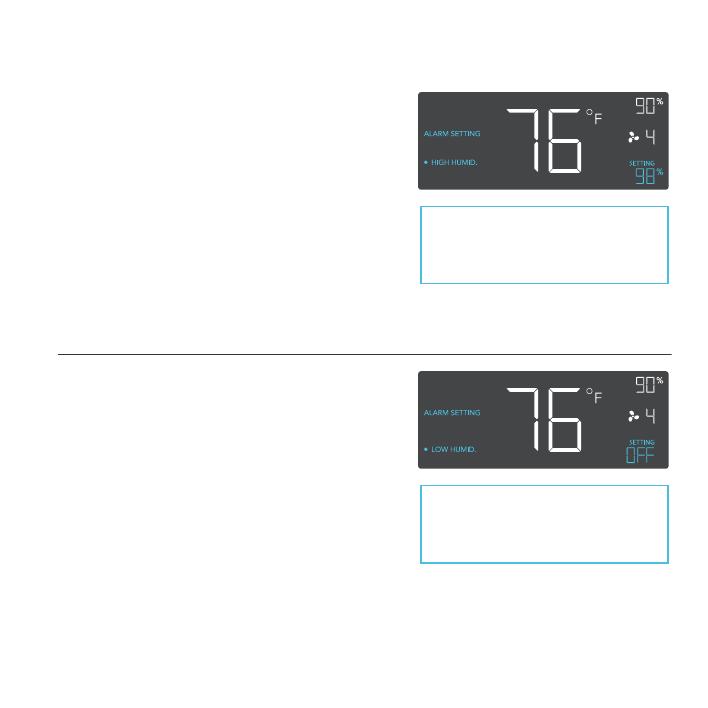
ALARM SETTING: HIGH HUMID.
In this settings mode, press the up and down
button to set a high humidity alarm. The alarm
will activate if the probe’s measured humidity
exceeds the humidity you have set in this
mode. When the alarm triggers, the fan will
start spinning at max speed regardless of your
other settings. You may also hold the up and
down button simultaneously to turn off this
alarm, in which the digits under settings will
show OFF. You will need to be in AUTO, ON,
or TIMER mode for this alarm to be able to
activate.
ALARM SETTING: LOW HUMID.
In this settings mode, press the up and down
button to set a low temperature alarm. The
alarm will activate if the probe’s measured tem-
perature falls below the temperature you have
set in this mode. When the alarm triggers, the
fan will start spinning at max speed regardless
of your other settings. You may also hold the
up and down button simultaneously to turn off
this alarm, in which the digits under settings
will show OFF. You will need to be in AUTO,
ON, or TIMER mode for this alarm to be able
to activate.
Note that alarm triggers can only
activate in AUTO, ON, or TIMER
Mode. Please leave ALARM
SETTING to arm the controller.
Note that alarm triggers can only
activate in AUTO, ON, or TIMER
Mode. Please leave ALARM
SETTING to arm the controller.
19
PROGRAMMING
DISPLAY BRIGHTNESS
To adjust the brightness of the display, please set the controller to OFF Mode, then press the up or
down button to increase or decrease the brightness level. Three brightness settings are available.
FAHRENHEIT OR CELSIUS
To change to displayed units between Fahrenheit and Celsius, please set the controller to OFF
Mode, then hold the up button for Fahrenheit (°F) or hold the down button for Celsius (°C).
ECO-MODE
The controller can be put into ECO display in which the screen will be turned off but all programs,
settings, and alarms will be running in the background. This can be done by pressing the LEAF
button. You may also do this while the controller is locked. To exit ECO display, simply press any
buttons.
TEMPERATURE CALIBRATION
To adjust the temperature that the probe sensor is measuring, please press the MODE and UP
button simultaneously. This can be done while the controller is any mode or setting. The calibration
cycle ranges from -8°F to 8°F (or -4°C to 4°C) and will be applied to the probe sensor’s measure-
ments.
HUMIDITY CALIBRATION
To adjust the humidity that the probe sensor is measuring, please press the MODE and DOWN
button simultaneously. This can be done while the controller is any mode or setting. The calibration
cycle ranges from -8% to 8% and will be applied to the probe sensor’s measurements.
CONTROLLER LOCK
To lock the controller to prevent settings to be changed accidentally, hold the LEAF button for two
or more seconds. While the display is locked, you will not be able to switch modes or changes any
settings. You will only be able to put the controller in ECO display by pressing the LEAF button.
Holding the LEAF button for two or more seconds will unlock the controller.
20
PROGRAMMING
CHECK FAN ALERT
This icon will flash when the fan's sensor detects interference to its operation.
Please check the fan for possible issues. If the fan is rotating, it may be static
pressure resistance and operating as intended. If the fan is not rotating, please
see the warranty page for replacement information. (This is only available on
certain models.)
TEMPERATURE ALARM ALERT
This icon will flash when the high or low temperature alarm that you have set has
been triggered.
HUMIDITY ALARM ALERT
This icon will flash when the high or low humidity alarm that you have set has been
triggered.
DISPLAY LOCK ALERT
This icon is visible when the controller has been locked. The icon will flash to alert
you that the controller is locked if you try to change the mode or settings.
ALERT ICONS
On the top left of the display is the alert icon section. Icons may flash when the controller wishes to
alert you that a particular function or alarm is being triggered.
  • Page 1 1
  • Page 2 2
  • Page 3 3
  • Page 4 4
  • Page 5 5
  • Page 6 6
  • Page 7 7
  • Page 8 8
  • Page 9 9
  • Page 10 10
  • Page 11 11
  • Page 12 12
  • Page 13 13
  • Page 14 14
  • Page 15 15
  • Page 16 16
  • Page 17 17
  • Page 18 18
  • Page 19 19
  • Page 20 20
  • Page 21 21
  • Page 22 22
  • Page 23 23
  • Page 24 24

AC Infinity AC-ALT16 User manual

Type
User manual

Ask a question and I''ll find the answer in the document

Finding information in a document is now easier with AI