VEVOR 6 Inch User manual

Type
User manual

VEVOR 6 Inch is a powerful ventilation fan designed to improve airflow and remove unwanted odors, fumes, and moisture from various indoor spaces. With its adjustable speed settings, you can customize airflow to suit your specific needs. The fan features a durable construction and a compact design, making it easy to install and maintain. Whether you need to ventilate a bathroom, kitchen, or workshop, VEVOR 6 Inch is up to the task.

VEVOR 6 Inch is a powerful ventilation fan designed to improve airflow and remove unwanted odors, fumes, and moisture from various indoor spaces. With its adjustable speed settings, you can customize airflow to suit your specific needs. The fan features a durable construction and a compact design, making it easy to install and maintain. Whether you need to ventilate a bathroom, kitchen, or workshop, VEVOR 6 Inch is up to the task.

VENTILATION FAN
USER MANUAL
We continue to be committed to provide you tools with competitive price. "Save
Half", "Half Price" or any other similar expressions used by us only represents
an estimate of savings you might benefit from buying certain tools with us
compared to the major top brands and doses not necessarily mean to cover all
categories of tools offered by us. You are kindly reminded to verify carefully
when you are placing an order with us if you are actually saving half in
comparison with the top major brands.
- 1 -
Have product questions? Need technical support? Please feel free to contact us:
NEED HELP? CONTACT US!
This is the original instruction, please read all manual instructions carefully before operating.
VEVOR reserves a clear interpretation of our user manual. The appear- ance of the product shall
be subject to the product you received. Please forgive us that we won't inform you again if there
are any technology or software updates on our product.
VENTILATION FAN
<Picture Only For Reference>
- 2 -
Contents
SAFETY PRECAUTIONS
PRODUCT DESCRIPTION
INSTALLATION
DIMENSION AND SPECIFICATION
POWERING AND SETUP
CLEANING
PROGRAMMING
FAQ
ATTENTIONS
SAFETY PRECAUTIONS
Improper operation may cause personal injury.
Improper operation may cause damage to the machine.
Improper operation may cause others object damage.
The symbol indicates that the user should pay high attention to
and pay attention to the drawing shows the situation to be
noted, and the left figure shows "Be careful of electric shock"
Disconnect the fan when moving from one location to another.
Do not use a power supply that does not meet the rated
voltage
The use of non compliant power supplies can cause fire or
electric shock.
If the machine emits smoke, odor, motor noise and other
abnormal conditions,Please do not use it. It may cause fire or
electric shock
Do not disassemble, repair or rectify the machine during
use.Doing so may result in fire or electric shock and personal
injury
- 3 -
BE CAREFUL
DO NOT use fan in window. Rain may create electrical
hazard.
Do not damage or arbitrarily change the original power
cord, and do not bend, forcibly pull, bind or press the power
cord under heavy objects.This will damage the power cord,
causing electric leakage fire or electric shock
If the machine is not used for a long time, please unplug
the power cord from the socket
If the power cord is damaged, contact your local service
center or a qualified electrician to install an appropriate
replacement cord to prevent any injury or damage
Never insert fingers, pencils, or any other object through
the guard when fan is running.
When the power cord is unplugged from the socket,
the plug should be unplugged. Do not pull the power
cord to forcibly pull the wire, which may cause
damage to the wire and lead to leakage or electric
shock
Please disconnect the power supply when cleaning
- 4 -
PRODUCT DESCRIPTION
TECHNICAL PARAMETER
Brand
Model
GX-04-100
GX-06-150
GX-08-200
Voltage
230 V
230 V
230 V
Frequency
50 Hz
50 Hz
50 Hz
Power
23 W
36 W
61 W
Speed
2900 RPM
2800 RPM
3000 RPM
Duct Size
Φ100/Φ125
Φ150/Φ160
Φ200
Power Cord Length
1.6 M
1.6 M
1.6 M
Working Ambient
Temperature
-10~ 45
-10~ 45
-10~ 45
PRODUCT STRUCTURE DIAGRAM
- 5 -
INSTALLATION
Prepare tools in advance:
Cross screwdriver, Hammer
- 6 -
Step 1
1Unscrew and loosen the metal rings using a Phillips screwdriver and pliers. See the(Fig.1.)
2Remove the motor box from the flange bracket.Remove the wind circle between the motor
box and the intake flange.See the(Fig.2.)
3Use the flange bracket to set your desired fan position. Mark the four mounting holes.See the
(Fig.3.)
4Drill four holes into the marked locations. Make sure your mounting area is structurally
sound and free from obstruction.See the(Fig.4.)
Fig.1.
Fig.2.
Fig.3.
Fig.4.
- 7 -
Step 2:
1If you are mounting onto anything other than a wood support or
stud, insert the included four wall anchors into the drilled mounting holes. You may need to
use a hammer to secure them through the holes. See the (Fig.5.)
2Paste the cushion onto the flange bracket to ensure that the hole
of the cushion is aligned with the hole of the flange bracket. See the (Fig.6.)
3Align the flange bracket’s holes with the wall anchors. Screw in
four wood screws with a screwdriver or drill to secure the flange bracket.Make sure its airflow
arrow is pointing in your desired direction.See the (Fig.7.)
Place the wind circle back into the intake flange and reposition the metal clamps over the
flanges if applicable.See the (Fig.8.)
Fig.5.
Fig.6.
Fig.7.
Fig.8.
- 8 -
4Slide the motor box back into the flange bracket, making sure its airflow arrow is pointing in
the same direction as the flange bracket’s arrow. Tighten the metal clamps using a Phillips
screwdriver and pliers to secure the motor box. See the (Fig.9.)
5Place the metal rings back onto the flanges and tighten the screws back to secure the
fan.See the (Fig.10.)
Step 3
1If installing ducting, purchase a suitable duct and duct clamp and secure it to both ends of
the fan to ensure tight sealing. Finally tighten the air duct clamp with a screwdriver.See the
(Fig.11.)
2If installing with rope hangers (sold separately), loop the ropes around the flanges and
tighten the rope to secure the fan.See the (Fig.12.)
Fig.11.
Fig.8.
Fig.10.
Fig.12.
Fig.8.
Fig.9.
- 9 -
DIMENSION AND SPECIFICATION
1Dimension
- 10 -
POWERING AND SETUP
Step 1:
Plug the duct fan’s 3-pin connector into the universal controller’s out 1 or out 2 port signified by
the fan/power symbol.Plug the sensor’s 4-pin connector into the controller’s sensor signified by
the controller symbol.See the(Fig.13.)
Step 2:
Lastly, to power both the fan and controller, plug the fans power cord into an AC power outlet.See
the(Fig.14.)
Fig.12.Fig.12.Fig.13.
Fig.14.
- 11 -
Tips:
Smart controllers with EC motors can support two fans of any size. The two EC-motor fans must
be plugged in to an outlet to power the fans and the controller. See images below.
- 12 -
CLEANING
Step 1:
Remove the motor box from the mounting flange. (Refer installation steps 1 and 2 to learn how to
of the mounting installation section to learn how to remove the motor box). (Fig.15.)
Step 2:
Use a damp cloth to clear the impeller and fan blades of any dust and debris. Remove the wind
circle in between the motor box and input flange. (Fig.16.)
Step 3:
Clear the stator blades of any dust and debris on the opposite end. Clean the area inside the
output and exhaust flanges. (Fig.17.)
Step 4:
Secure the motor box onto the mounting flanges. Refer installation step 2-3 to learn how to
flanges. secure the motor box. (Fig.18.)
Fig.15.
Fig.16.
Fig.17.
Fig.18.
- 13 -
PROGRAMMING
BUTTON DESCRIPTION
1. MODE BUTTON
Cycles through the controller's temperature/humidity programming: ON, OFF,TIMER, AUTO (4
triggers),and ALARM (4 settings).
2. UP / DOWN BUTTON
Adjusts the settings of the mode that you are in. Up button raises and down button lowers.
Hold both to turn off triggers.
3. LEAF BUTTON
Turns the screen off while programs run in the background. Hold for two seconds to lock or
unlock the LCD display.
4. PROBE TEMP
Displays the current temperature that the corded sensor probe is measuring. Shows “- -” if no
probe is plugged in.
5. CONTROLLER MODE
Displays the mode that the controller is currently in.Pressing the mode button cycles through
the modes.
- 14 -
6. ALERT ICONS
Displays the alerts and statuses from the controller, including the alarm and the screen lock.
7. PROBE HUMIDITY
Displays the current humidity that the corded sensor probe is measuring. Shows “- -” if no
probe is plugged in.
8. FAN SPEED
Displays the current speed the fan is running at, or what speed it should be running at if no
fans are plugged in.
9. SETTING
Displays the value you set for the current mode. Pressing the up or down button changes the
value.
OPERATION DESCRIPTION
MODE SETTING
Pressing the Mode button will cycle through the controller’s available programming modes and
settings: ON Mode, OFF Mode, TIMER Mode, AUTO Mode (4 triggers), ALARM Settings (4
settings).
ON MODE
In this mode, the fan will heat continuously regardless of temperature or humidity. Use this
mode to set the fan's maximum blowing strength, ranging from 0-10, when triggers are
activated.
- 15 -
OFF MODE
In this mode, the fan will not run regardless of temperature or humidity. Pushing the up or
down button will change the display’s brightness, ranging in 1/2/3/A3. On setting A3, the
display will dim its brightness down to 1 if the device is left unattended for 30 seconds.
Holding the up or down button will change the display’s units to F or C, respectively.
TIMER MODE
In this mode, pressing the up or down button will set the timer. The fan will ramp up to ON
Mode’s setting until the timer’s clock runs out. It will begin spinning 5 seconds after the timer
is set.
Leaving the timer mode while it’s running will pause it until you return to this mode.
- 16 -
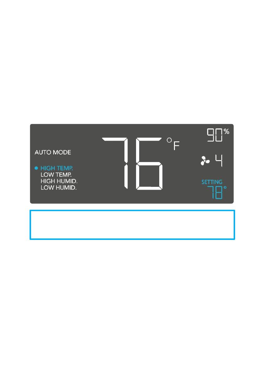
TRIGGER MODE: HIGH TEMPERATURE
In this mode, pressing the up or down button sets the high temperature trigger. The fan will
activate if the probe’s reading meets or exceeds this trigger.
It will gradually ramp up until it reaches the ON Mode’s setting. If the probe’s reading falls
below your trigger, the fan will turn off. We recommend turning this trigger OFF when not in
use during set up by holding the up and down buttons together.
You may set this trigger below the low temperature trigger to create a range where the fan is
active.
TRIGGER MODE: LOW TEMPERATURE
In this mode, pressing the up or down button sets the low temperature trigger. The fan will
activate if the probe’s reading meets or falls below this trigger.
It will gradually ramp up until it reaches the ON Mode’s setting. If the probe’s reading rises
above your trigger, the fan will turn off. We recommend turning this trigger OFF when not in
use during set up by holding the up and down buttons together.
You may set this trigger above the high temperature trigger to create a range where the fan is
active.
Note that this trigger can activate as long as you are in AUTO Mode,
even if you are viewing a different trigger within AUTO Mode.
- 17 -
TRIGGER MODE: HIGH HUMIDITY
In this mode, pressing the up or down button sets a high humidity trigger. The fan will activate
if the probe’s reading meets or exceeds this trigger.
It will gradually ramp up until it reaches the ON Mode’s setting. If the probe’s reading falls
below your trigger, the fan will turn off. We recommend turning this trigger OFF when not in
use during set up by holding the up and down buttons together.
You may set this trigger below the low humidity trigger to create a range where the fan is
active.
Note that this trigger can activate as long as you are in AUTO Mode,
even if you are viewing a different trigger within AUTO Mode.
Note that this trigger can activate as long as you are in AUTO Mode,
even if you are viewing a different trigger within AUTO Mode.
- 18 -
TRIGGER MODE: LOW HUMIDITY
In this mode, pressing the up or down button sets the low humidity trigger. The fan will
activate if the probe’s reading meets or falls below the trigger.
It will gradually ramp up until it reaches the ON Mode’s setting. If the probe’s reading rises
above your trigger, the fan will turn off. We recommend turning this trigger OFF when not in
use during set up by holding the up and down buttons together.
You may set this trigger above the high humidity trigger to create a range where the fan is
active.
ALARM SETTING: HIGH TEMPERATURE
In this mode, pressing the up and down button sets a high temperature alarm. The alarm will
sound and its icon will flash if the probe’s reading exceeds the set temperature.
To activate the alarm, leave the alarm mode. The alarm will turn
OFF if the probe’s reading falls below the trigger or if any button is pressed. You can also set
the alarm OFF by holding the up and down buttons together.
Note that this trigger can activate as long as you are in AUTO Mode,
even if you are viewing a different trigger within AUTO Mode.
- 19 -
You may set this alarm below the low temperature trigger to create an operating range.
ALARM SETTING: LOW TEMPERATURE
In this mode, pressing the up and down button sets a low temperature alarm. The alarm will
sound and its icon will flash if the probe’s reading falls below the set temperature.
To activate the alarm, leave the alarm mode. The alarm will turn OFF if the probe’s reading
rises above the trigger or if any button is pressed. You can also set the alarm OFF by holding
the up and down buttons together.
You may set this alarm above the high temperature trigger to create an operating range.
Note that alarm triggers can only activate in AUTO, ON, or TIMER
Mode. Please leave ALARM SETTING to arm the controller.
  • Page 1 1
  • Page 2 2
  • Page 3 3
  • Page 4 4
  • Page 5 5
  • Page 6 6
  • Page 7 7
  • Page 8 8
  • Page 9 9
  • Page 10 10
  • Page 11 11
  • Page 12 12
  • Page 13 13
  • Page 14 14
  • Page 15 15
  • Page 16 16
  • Page 17 17
  • Page 18 18
  • Page 19 19
  • Page 20 20
  • Page 21 21
  • Page 22 22
  • Page 23 23
  • Page 24 24
  • Page 25 25
  • Page 26 26
  • Page 27 27
  • Page 28 28

VEVOR 6 Inch User manual

Type
User manual

VEVOR 6 Inch is a powerful ventilation fan designed to improve airflow and remove unwanted odors, fumes, and moisture from various indoor spaces. With its adjustable speed settings, you can customize airflow to suit your specific needs. The fan features a durable construction and a compact design, making it easy to install and maintain. Whether you need to ventilate a bathroom, kitchen, or workshop, VEVOR 6 Inch is up to the task.

Ask a question and I''ll find the answer in the document

Finding information in a document is now easier with AI