
USER MANUALUSER MANUAL
AIRLIFT SERIES
SHUTTER EXHAUST FAN SYSTEM


3
WELCOME
Thank you for choosing AC Infinity. We are committed to product quality and friendly customer service.
If you have any questions or suggestions, please don’t hesitate to contact us. Visit www.acinfinity.com
and click contact for our contact information.
EMAIL
support@acinfinity.com
WEB
www.acinfinity.com
LOCATION
Los Angeles, CA

4
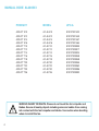
PRODUCT
AIRLIFT S10
AIRLIFT S12
AIRLIFT S14
AIRLIFT S16
AIRLIFT T10
AIRLIFT T12
AIRLIFT T14
AIRLIFT T16
AIRLIFT T18
AIRLIFT T20
AIRLIFT T22
AIRLIFT T30
AIRLIFT T36
MODEL
AC-ALS10
AC-ALS12
AC-ALS14
AC-ALS16
AC-ALT10
AC-ALT12
AC-ALT14
AC-ALT16
AC-ALT18
AC-ALT20
AC-ALT22
AC-ALT30
AC-ALT36
UPC-A
819137021433
819137021440
819137021457
819137021464
819137020900
819137020917
819137020924
819137020948
819137020948
819137020955
819137020962
819137020986
819137020993
MANUAL CODE AL2005X1
SERIOUS INJURY OR DEATH. Please do not touch the fan's impeller and
blades. Secure all nearby objects including wires and cables from coming
into contact with the fan’s impeller and blades. Use caution when deciding
where to install this fan.

5
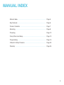
MANUAL INDEX
Manual Index .................................................................................
Key Features .................................................................................
Product Contents ...........................................................................
Mounting ........................................................................................
Powering
Daisy Chain and Setup ..................................................................
Programming .................................................................................
Other AC Infinity Products .............................................................
Warranty ........................................................................................
Page 5
Page 6
Page 7
Page 8
Page 12
Page 13
Page 14
Page 23
Page 24

6
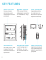
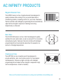
KEY FEATURES
SMART CONTROLLER
Programmable controller
with corded sensor can
adjust airflow in response to
temperature and humidity.
HEAVY DUTY BUILD
Fans are enclosed in
steel and wire guards to
withstand shocks and harsh
environments.
WEATHERPROOF
The shutter fan unit is sealed
to Ingress Protection 44
standards to be resistant to
liquid and dust.
DUAL BALL BEARINGS
Long life bearings rated at
67,000 hours. Also allows
the fan to be mounted in any
direction.
EFFICIENT EC-MOTOR
PWM controlled EC-motor
enables precise speed control,
low noise, and higher energy
efficiency.
SPEED CONTROLLER
Single button controller with
circular readout display that
enables fan speed control in
eight speeds.

7
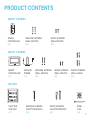
PRODUCT CONTENTS
AIRLIFT S-SERIES
FAN UNIT
SPEED
CONTROLLER
(x1)
MACHINE SCREWS
(WALL MOUNT)
(x2)
WOOD SCREWS
(WALL MOUNT)
(x2)
MACHINE SCREWS
(SHUTTER MOUNT)
(x4)
WIRE
TIES
(x4)
SHUTTER
FAN UNIT
(x1)
WOOD SCREWS
(SHUTTER MOUNT)
(x4)
AIRLIFT T-SERIES
SENSOR
PROBE
(x1)
SMART
CONTROLLER
(x1)
WOOD SCREWS
(WALL HANG)
(x2)
WOOD SCREWS
(WALL MOUNT)
(x2)
MACHINE SCREWS
(WALL MOUNT)
(x2)

8
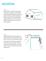
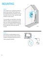
MOUNTING
STEP 1
When installing in a large room like a green
house, barn, or garage, it is recommended
that the shutter fan should be mounted on the
opposite side of any ventilation openings for
better air circulation. The fan should also be
positioned higher in the room to exhaust out
heated air, which will rise on its own due to
natural convection.
STEP 2
Measure the dimensions of the shutter fan’s
mounting frame which will go through the wall.
Select a location on the wall where you will be
mounting the fan. Please make sure that the
wall is free of any wires or pipes. Using the
measurements of the shutter fan, use a level
and ruler to draw an outline of the area to be
drilled and cut.
Mounting Hole

9
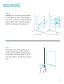
MOUNTING
STEP 4
Position the shutter fan through the hole cut
in step 3. Use it to measure the positioning of
the mounting screws then remove the fan unit.
Then using a drill bit, create the four mounting
holes.
STEP 3
Depending on your mounting surface material,
use the appropriate tools to cut into the wall.
Use a drill or a hand saw to create an opening
large enough to insert a saw blade or jigsaw
inside the outlined area of the wall panel.
Thinner Woods or Plastic Woods,Tougher Plastic or, Metal

10
MOUNTING
STEP 5
From inside the room, position the shutter fan
back into the opening of the fan. Make sure
the controller connectors and power cord is on
the inside of the room. Then, use the included
hardware to secure the fan.
If you are using your own shutter, remove the
AIRLIFT's shutter by unscrewing the nuts and
bolts from the fan guard. Reassemble the fan
guard onto your existing shutter by reapplying
the nuts and bolts in the same mounting
locations.
STEP 6
Once the fan is mounted securely you can
then mount the controller using the included
hardware. Place the controller near the fan in
order to power the controller.
Inside

11
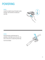
POWERING
STEP 2
Secure the sensor probe head near by,
preferably in the hottest area of the room. You
can use the wire tie to secure the probe away
from the fan blades.
STEP 1
Locate the connector plug of the sensor probe
and plug it into the bottom of the thermal
controller.

12
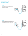
POWERING
STEP 4
Lastly, to power the fan and the controller, plug
the fans power cord into an AC power outlet.
STEP 3
Connect the molex end from the fan into the
bottom of the controller.

13
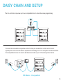
DAISY CHAIN AND SETUP
The fan controller can power up to two compatible fans to share the same programming.
The controller included is compatible with AC Infinity fan models that contain an EC-motor.
Typically, EC-motor fans will have a separate cord coming out of it for the power and the controller.
The compatible fans do not need to be the same model or part of the same product series.
EC Motor - Compatible

14
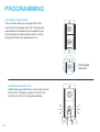
FAN SPEED ADJUSTING
The controller features a single button that
controls the fan speed from 0-8. Pressing the
speed button increases the fan speed in one
unit increments. Pressing the button at the 8
setting will set the fan speed back to 0.
POWERING ON AND OFF
Holding the speed button for 4 seconds will turn
the fan OFF. Pressing it again from OFF will
turn the fan ON at its last speed setting.
PROGRAMMING
Fan Speed
Indicator

15
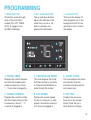
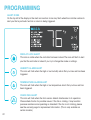
PROGRAMMING
1. MODE BUTTON
This button cycles through
each of the controller's
modes: ON, OFF, TIMER,
AUTO (4 triggers), and
ALARM (4 settings).
4. PROBE TEMP.
Displays the current tempera-
ture that the corded sensor
probe is measuring. Shows
“- -” if no probe is plugged in.
8. FAN SPEED
Displays the current speed
the fan is running at, or what
speed it should be running at
if no fans are plugged in.
6. ALERT ICONS
This area displays the alerts
and statuses from the
controller including alarms
and screen lock.
9. SETTING
Displays the value you
have set for the current
mode. Press the up or
down button to change.
7. PROBE HUMIDITY
Displays the current humidity
that the corded sensor probe
is measuring. Shows “- -” if
no probe is plugged in.
5. CONTROLLER MODE
This area displays the mode
that the controller is currently
in. Press the Mode Button to
cycle through the modes.
3. LEAF BUTTON
This turns the display off
while programs run in the
background. Hold for two
seconds to lock or unlock
the display.
2. UP / DOWN BUTTON
The up and down buttons
adjusts the settings of the
mode that you are in. Up
button increases and
down button decreases.
21 3
4
7
8
9
6
5

16
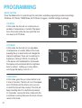
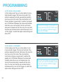
ON MODE
In this mode, the fans will run continuously re-
gardless of temperature or humidity. The speed
set in this mode will be the max speed the fans
can reach in AUTO Mode.
OFF MODE
In this mode, the fans will not run regardless
of temperature or humidity. While in this mode,
pressing the up or down button will change the
display’s brightness. There are four settings for
brightness, (Setting:1/2/3/A3). On setting A3,
if the device is left unattended for 30 seconds,
the display will automatically dim its brightness
back to setting 1. Holding up or down button
will change the display’s units F or C.
PROGRAMMING
MODE SETTING
Press the Mode button to cycle through the controller’s available programming modes and settings:
ON Mode, OFF Mode, TIMER Mode, AUTO Mode (4 triggers), ALARM Settings (4 settings).
TIMER MODE
In this mode, press the up or down button to set
a time for the timer. The fans will run at the speed
set in ON Mode until the timer’s clock runs out,
in which the fans will stop running. The clock will
begin counting down if no buttons are pressed
for 3 seconds. Leaving the timer mode while the
countdown is running will pause the clock until you
return to this mode.

17
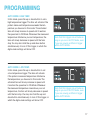
PROGRAMMING
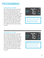
AUTO MODE: HIGH TEMP.
In this mode, press the up or down button to set a
high temperature trigger. The fans will activate if the
probe’s measured temperature exceeds the tem-
perature you have set in this mode. The activated
fans will slowly increase in speed until it reaches
the speed set in ON Mode. Whenever the measured
temperature falls below your set temperature, the
fans will slowly decrease in speed until the fans
stop. You may also hold the up and down button
simultaneously to turn off this trigger, in which the
digits under settings will show OFF.
AUTO MODE: LOW TEMP.
In this mode, press the up or down button to set
a low temperature trigger. The fans will activate
if the probe’s measured temperature falls below
the temperature you have set in this mode. The
activated fans will slowly increase in speed until
it reaches the speed set in ON Mode. Whenever
the measured temperature rises above your set
temperature, the fans will slowly decrease in speed
until the fans stop. You may also hold the up and
down button simultaneously to turn off this trigger, in
which the digits under settings will show OFF.
Note that this trigger can activate as
long as you are in AUTO Mode, even
if you are viewing a different trigger
within AUTO Mode.
Note that this trigger can activate as
long as you are in AUTO Mode, even
if you are viewing a different trigger
within AUTO Mode.

18
PROGRAMMING
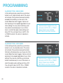
AUTO MODE: HIGH HUMID.
In this mode, press the up or down button to set a
high humidity trigger. The fans will activate if the
probe’s measured humidity exceeds the humidity
you have set in this mode. The activated fans will
slowly increase in speed until it reaches the speed
set in ON Mode. Whenever the measured humidity
falls below your set humidity, the fans will slowly
decrease in speed until the fans stop. You may also
hold the up and down button simultaneously to turn
off this trigger, in which the digits under settings will
show OFF.
AUTO MODE: LOW HUMID.
In this mode, press the up or down button to set
a low humidity trigger. The fans will activate if the
probe’s measured humidity falls below the humidity
you have set in this mode. The activated fans
will slowly increase in speed until it reaches the
speed set in ON Mode. Whenever the measured
humidity rises above your set temperature, the
fans will slowly decrease in speed until the fans
stop. You may also hold the up and down button
simultaneously to turn off this trigger, in which the
digits under settings will show OFF.
Note that this trigger can activate as
long as you are in AUTO Mode, even
if you are viewing a different trigger
within AUTO Mode.
Note that this trigger can activate as
long as you are in AUTO Mode, even
if you are viewing a different trigger
within AUTO Mode.

19
PROGRAMMING
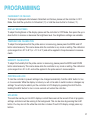
ALARM SETTING: HIGH TEMP.
In this settings mode, press the up and down
button to set a high temperature alarm. The
alarm will activate if the probe’s measured
temperature exceeds the temperature you have
set in this mode. When the alarm triggers, the
fan will start spinning at max speed regardless
of your other settings. You may also hold the
up and down button simultaneously to turn off
this alarm, in which the digits under settings
will show OFF. You will need to be in AUTO,
ON, or TIMER mode for this alarm to be able
to activate.
Note that alarm triggers can only
activate in AUTO, ON, or TIMER
Mode. Please leave ALARM
SETTING to arm the controller.
ALARM SETTING: LOW TEMP.
In this settings mode, press the up and down
button to set a low temperature alarm. The
alarm will activate if the probe’s measured tem-
perature falls below the temperature you have
set in this mode. When the alarm triggers, the
fan will start spinning at max speed regardless
of your other settings. You may also hold the
up and down button simultaneously to turn off
this alarm, in which the digits under settings
will show OFF. You will need to be in AUTO,
ON, or TIMER mode for this alarm to be able
to activate.
Note that alarm triggers can only
activate in AUTO, ON, or TIMER
Mode. Please leave ALARM
SETTING to arm the controller.

20
PROGRAMMING
ALARM SETTING: HIGH HUMID.
In this settings mode, press the up and down
button to set a high humidity alarm. The alarm
will activate if the probe’s measured humidity
exceeds the humidity you have set in this
mode. When the alarm triggers, the fan will
start spinning at max speed regardless of your
other settings. You may also hold the up and
down button simultaneously to turn off this
alarm, in which the digits under settings will
show OFF. You will need to be in AUTO, ON,
or TIMER mode for this alarm to be able to
activate.
ALARM SETTING: LOW HUMID.
In this settings mode, press the up and down
button to set a low humidity alarm. The alarm
will activate if the probe’s measured humidity
falls below the temperature you have set in this
mode. When the alarm triggers, the fan will start
spinning at max speed regardless of your other
settings. You may also hold the up and down
button simultaneously to turn off this alarm, in
which the digits under settings will show OFF.
You will need to be in AUTO, ON, or TIMER
mode for this alarm to be able to activate.
Note that alarm triggers can only
activate in AUTO, ON, or TIMER
Mode. Please leave ALARM
SETTING to arm the controller.
Note that alarm triggers can only
activate in AUTO, ON, or TIMER
Mode. Please leave ALARM
SETTING to arm the controller.
Page is loading ...
Page is loading ...
Page is loading ...
Page is loading ...
Page is loading ...
Page is loading ...
Page is loading ...
Page is loading ...
-
 1
1
-
 2
2
-
 3
3
-
 4
4
-
 5
5
-
 6
6
-
 7
7
-
 8
8
-
 9
9
-
 10
10
-
 11
11
-
 12
12
-
 13
13
-
 14
14
-
 15
15
-
 16
16
-
 17
17
-
 18
18
-
 19
19
-
 20
20
-
 21
21
-
 22
22
-
 23
23
-
 24
24
-
 25
25
-
 26
26
-
 27
27
-
 28
28


Ask a question and I''ll find the answer in the document
Finding information in a document is now easier with AI
Related papers
-
AC Infinity AC-ALT16 User manual
-
AC Infinity RAXIAL User manual
-
AC Infinity Airtitan Series Crawlspace And Basement Ventilation Fans User manual
-
AC Infinity CLOUDLINE PRO User manual
-
AC Infinity AC-AFT7-BE User manual
-
AC Infinity AI-CP2H User manual
-
-
-
AC Infinity AC-BFP4 User manual
-
Other documents
-
 ELITEFOUR JC 612 User manual
-
VEVOR 6 Inch User manual
-
Abestorm NeatyFresh Pro User manual
-
PureLink Media Axis Matrix Switchers User manual
-
 Seville Classics OFF65871 User manual
-
 Seville Classics AIRLIFT OFF65894 Operating instructions
-
 Seville Classics OFF65815 User manual
-
 Seville Classics OFF65871 Assembly Instructions
-
 Seville Classics OFF65872 Assembly Instructions
-
 Seville Classics OFFK65822 Installation guide


