Page is loading ...

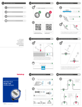
ALWAYS use new gskets
(PE or EPDM).
The coupling’s seling
surfce must be clen
nd even.
The piping must be parallel and match the meter.
If you hve smrt phone you cn enter this QR code nd wtch
our instlltion film online. Or you cn wtch the film on http://www.
kmstrup.dk/hrdlink/mc21/index.html.
Torque
If pipe instlltion is skew to the effect tht the prescribed tightening
torques would be exceeded, telescopic coupling ought to be instlled.
¾” Mx. 15 Nm
1” Mx. 30 Nm
¾”: Mx. 15 Nm
1”: Mx. 30 Nm
MULTICAL® 21
Installation guide
South Africa
Kmstrup A/S • 55121475_A3_ZA_04.2016
Kamstrup A/S · Industrivej 28, Stilling · DK-8660 Skanderborg
T: +45 89 93 10 00 · F: +45 89 93 10 01 · info@kamstrup.com
Customer lbel, e.g. wter compny logo or the meter seril no.
Opticl eye for reding nd configurtion
Grphic flow indictor
Type number
(includes informtion on
meter size, overll length etc.)
Seril no. nd production yer
Configurtion
(with informtion on disply
resolution nd encryption level etc.)
According to SANS 1529
Metrologicl clss of meters 2
Pressure loss: P60
Br code with seril number
Expiry yer of bttery
Temperture clss
Meter size qp
Softwre version nd dynmic rnge
Pressure stge nd protection clss
Approvl cc. to South Africn Bureu of Stndrds

A Recommended wter meter position.
B Recommended wter meter position.
C Used for ’well instlltion’. Air build-up my occur.
D The meter functions optimlly, but the disply is ’upside down’.
1.5 Operating pressure
In order to void cvittion nd secure correct mesurement under
ll circumstnces the operting pressure in the pipe instlltion must
observe the test conditions of OIML R 49, which mens tht the sttic
pressure immeditely fter the meter (downstrem) must lwys be
minimum 0.03 MP (0.3 br).
You must lwys use new gskets in originl qulity. Following gskets
cn be used:
Cold water Hot water
¾” 2 mm EPDM or PE 2 mm PTFE with silicte fill
1” 3 mm EPDM or PE 3 mm PTFE with silicte fill
The flow direction is indicted by n rrow on the side of the meter cse.
During instlltion it must be secured tht the meter is mounted without
mechnicl bis in the connection pipes. The couplings must be
tightened with mximum the following torque:
¾” 15 Nm
1” 30 Nm
If tight connection cnnot be obtined within these limits, the pipe
instlltion must be corrected in order to remove strins. Alterntively,
telescopic coupling must be instlled.Such couplings cn be supplied
by Kmstrup A/S.
For seling you cn use the seling wire holes on the lower side of the
threded connections.
Mounting the meter you must mke sure tht the threded length of the
couplings does not prevent proper tightening of the seling surfce nd
tht PN10 or PN16 couplings re used.
MULTICAL® 21 hs lrge-meshed striner (filter) pre-mounted in the
meter’s inlet connection.
Furthermore, nonreturn vlve cn be mounted conceled in the
meter’s outlet socket. 2 or 3 mm gskets must be used for mounting.
The non-return vlve must be pressed into the outlet of the meter; the
blck o-ring pointing inwrds in the meter. Press firmly the vlve into
the meter outlet socket until it reches limit stop.
FLOW
Gasket Gasket
Non-return valve
Flow
Service
When the meter hs been mounted in the system neither welding nor
freezing is llowed. Dismount the meter from the system before strting
such work.
In order to fcilitte replcement of the meter, closing vlves should be
mounted on both sides of the meter.
Under norml operting conditions no pipe striner is required in front
of the meter. Non-return vlves must be mounted ccording to locl
regultions.
1.3 Installation angle of MULTICAL® 21
MULTICAL® 21 cn be mounted t ll ngles nd positions.
Kmstrup A/S recommend tht the disply is mounted so tht it is esy
to red, if possible.
Thus, the meter cn be mounted in usul horizontl instlltion. It cn
be mounted verticlly in n scending pipe, it cn be mounted t ny
ngle nd it cn be mounted with its disply pointing downwrds, e.g
under roof.
Mounting the meter in downpipe, you must be wre tht the disply
will in tht cse be ’upside down’.
1.4 Straight inlet
MULTICAL® 21 requires neither stright inlet nor stright outlet to meet
the South Africn Ntionl Stndrd SANS 1529-1:2006. A stright inlet
section will only be necessry in cse of hevy flow disturbnces before
the meter.
1 General information
Red this guide before instlling the wter meter.
MULTICAL® 21 is compct electronic wter meter used for wter
consumption mesurement in the tp wter supplies of homes,
commercil nd industril buildings. The meter is vilble in two
versions for cold nd hot wter respectively.
MULTICAL® 21 is intended for mintennce-free opertion for up to 16
yers, depending on the instlled bttery type.
MULTICAL® 21 is hermeticlly closed, nd it is, therefore, impossible
to service the meter without breking the sel. This mens tht ll
service, including bttery chnge, must be crried out by n uthorized
Kmstrup Service Center.
Certin chnges of configurtion, however, re possible vi the built-in
opticl eye without dismounting the meter from the instlltion. Further
detils pper from dt sheet nd technicl description.
1.1 Permissible operating conditions / measuring
ranges
Medium temperture
cold wter meter: 0.1 °C...50 °C
Medium temperture
hot wter meter: 0.1 °C...70 °C
Pressure stge: PN16
Mechnicl environment: M1 (MID) Fixed instlltion with minimum
vibrtion.
Electromgnetic
environmentl clss: E1 nd E2 (MID). Residentil nd
commercil
Protection clss: IP68
Climtic environment: 2 °C...55 °C. Condensing humidity.
(indoors mounted in utility rooms nd
outdoors in meter wells). Instlltion in
direct sunlight must be voided.
1.2 Installation requirements
MULTICAL® 21 hs built-in dt communiction, which enbles remote
reding of the meter.
If instlled in pits or bsements the meter must in some cses be fitted
with n externl ntenn in order to secure optimum communiction.
The ntenn must be plced outside pit or bsement.
Prior to instlltion of MULTICAL® 21 the system should be flushed while
fitting piece replces the meter. Mount the meter with couplings.
Be wre, when instlling the wter meter in existing threded piping,
tht the coupling’s nut must grb t lest two full threds on the meter.
Otherwise, Kmstrup A/S recommends replcement of the couplings.
1.6 Info codes and display
When MULTICAL® 21 leves Kmstrup A/S, it hs been tested nd
verified nd the counter hs been reset.
The number of m3 is displyed by five lrge digits. The smll digits re
decimls fter the point. (or number of liters). A number of info codes
cn be displyed, of which ’DRY’ nd ’RADIO OFF’ will be ctivted nd
flsh upon delivery. Furthermore, the two smll squres in the bottom
right-hnd corner flsh to indicte tht the meter is ctive.
Info code ’DRY’ indictes tht there is ir in the meter, the info code
disppers when the meter is wter-filled.
The info code ’RADIO OFF’ indictes tht the meter is still in trnsport
mode with the built-in rdio trnsmitter turned off. The trnsmitter turns
on utomticlly when the first litre of wter hs run through the meter.
The rdio trnsmitter remins on, nd the info code signl in the disply
switches off.
The flow rrows in the left side of the disply indicte wter flow through
the meter. If the wter is stgnnt, ll rrows will be off.
The tble below describes the different info codes in the disply.
The figure fter the ’A’ sttes how mny times the meter hs been
djusted. In completely new meter both of these chrcters will be
out.
Lbortories which hve reverified nd djusted or reset the meter must
supply the meter with lbel with informtion on the current djustment
figure.
Info code
flashes in the display
Meaning
LEAK The Wter hs not been stgnnt in the
meter for minimum one continuous hour
during the ltest 24 hours.
This cn be sign of leky fucet or toilet
cistern.
BURST The wter flow hs exceeded
preprogrmmed limit for minimum 30
minutes which is sign of burst pipe.
TAMPER Attempt of frud. The meter is no longer
vlid for billing purposes.
DRY The meter is not wter-filled.
REVERSE The wter flows through the meter in the
wrong direction.
RADIO OFF The meter is still in trnsport mode with
the built-in rdio trnsmitter turned off.
The trnsmitter turns on utomticlly
when the first litre of wter hs run through
the meter.
■■ (two squre ’dots’) Two smll squres tht flsh lterntely
indicte tht the meter is ctive.
/