Black Box MCX Management Controller Software Owner's manual
- Category
- Software
- Type
- Owner's manual

24/7 TECHNICAL SUPPORT AT 1.877.877.2269 OR VISIT BLACKBOX.COM
MCX
CONTROLLER
SOFTWARE
MCX-MGMT
USER MANUAL
224.1.1.1
STREAMING
1920x1080p60
RGB, 8 bits
D88039E5B59C
169.254.157.181
V4.0.1.0
Fast Switch
All Displays
all rx
224.1.1.2
STREAMING
1920x1080p60
YCBCR_ 444, 8 bits
00BC102221A9
169.254.170.33
V4.0.1.0
Genlock
224.1.1.5
STREAMING
1920x1080p60
RGB, 8 bits
00BC1022229B
169.254.156.34
V4.0.1.0
Fast Switch
224.1.1.3
STREAMING
1920x1080p60
RGB, 8 bits
341B22F00104
169.254.5.1
V4.0.1.0
Genlock
224.1.1.3
STREAMING
3840x2160p30
RGB, 8 bits
341B22F00115
169.254.22.1
V4.0.1.0
Multiviewer
Video Routing
IP address of MCX API Server
MCX Management Console 2.5.0
Wall Routing Multiview Routing HDMI Audio Routing Analog Audio Routing 12S Audio Routing RS-232 Routing Infrared Routing USB Routing Device Management
127.0.0.1 Disconnect
6970
X
Decoders
Encoders
224.1.1.3
STREAMING
1920x1080p60
RGB, 8 bits
008C 102221A7
169.254.168.33
V4.0.1.0
Fast Switch
224.1.1.1
STREAMING
1920x1080p59.94
RGB, 8 bits
008C 10222295
169.254.150.35
V4.0.1.0
224.1.1.5
STREAMING
1920x1080p60.01
YCBCR_444, 8 bits
008C 1022229C
169.254.157.34
V4.0.1.0
224.1.1.2
STREAMING
1920x1080p60
YCBCR_444, 8 bits
008C 10222294
169.254.149.34
V4.0.1.0

2
NEED HELP?
LEAVE THE TECH TO US
LIVE 24/7
TECHNICAL
SUPPORT
1.877.87 7. 2269
1. 8 7 7. 8 7 7. 2 2 6 9 BLACKBOX.COM
TABLE OF CONTENTS
1. OVERVIE W ...................................................................................................................................................................................... 6
2. INSTALLATION .............................................................................................................................................................................. 7
2.1 Installing the MCX Controller ..................................................................................................................................................................7
2.1.1 MCX Controller Installer for Windows ............................................................................................................................................................7
2.1.2 Point-to-Point Setup .........................................................................................................................................................................................11
2.2 Launching the MCX Management Console ......................................................................................................................................... 11
MCX Management Console Device Status ..........................................................................................................................................................13
3. MCX MANAGEMENT CONSOLE OVERVIEW ............................................................................................................................. 14
3.1 Data Routing and Switching ..................................................................................................................................................................14
3.2 MCX Management Console Interface ..................................................................................................................................................14
3.3 MCX Controller Video Modes ................................................................................................................................................................15
3.4 HDMI Audio Routing from the MCX Controller .................................................................................................................................... 16
3.5 RS-232 and Infrared (IR) Routing .......................................................................................................................................................... 16
3.6 USB 2.0 Routing ......................................................................................................................................................................................16
4. USING THE MCX MANAGEMENT CONSOLE ............................................................................................................................ 17
4.1 Video Routing Tab ..................................................................................................................................................................................17
4.1.1 Confirming Which Encoders are Joined to Decoders ...............................................................................................................................17
4.1.2 Genlock Mode ...................................................................................................................................................................................................18
4.1.2.1 Setting a Decoder to Genlock Mode ...............................................................................................................................................18
4.1.2.2 Assigning a New Source to a Single Decoder (RX) .....................................................................................................................19
4.1.2.3 Sending a Single Source to One or Multiple Decoders ...............................................................................................................20
4.1.2.4 Sending a Single Source to All Decoders (RX) .............................................................................................................................20
4.1.2.5 Stopping/Starting Video ....................................................................................................................................................................20
4.1.2.6 Disconnecting a Source from a Decoder (RX) .............................................................................................................................. 22
4.1.3 Fast Switch Mode .............................................................................................................................................................................................22
4.1.3.1 Setting a Decoder to Fast Switch Mode .........................................................................................................................................23
4.1.3.2 Assigning a New Source to a Single Decoder (RX) .....................................................................................................................24
4.1.3.3 Sending a Single Source to One or Multiple Decoders ...............................................................................................................24
4.1.3.4 Sending a Single Source to All Decoders (RX) .............................................................................................................................24
4.1.3.5 Stopping/Starting Video .................................................................................................................................................................... 24
4.1.3.6 Disconnecting a Source from a Decoder (RX) ..............................................................................................................................25
4.1.4 Genlock Scaling Mode ..................................................................................................................................................................................... 25
4.1.4.1 Setting a Decoder to Genlock Scaling Mode ................................................................................................................................. 25
4.1.4.2 Assigning a New Source to a Single Decoder (RX)......................................................................................................................27
4.1.4.3 Sending a Single Source to One or Multiple Decoders ...............................................................................................................27
4.1.4.4 Sending a Single Source to All Decoders (RX)..............................................................................................................................27
4.1.4.5 Stopping/Starting Video .................................................................................................................................................................... 27
4.1.4.6 Disconnecting a Source from a Decoder (RX) .............................................................................................................................. 27

3
1. 8 7 7. 8 7 7. 2 2 6 9 BLACKBOX.COM
NEED HELP?
LEAVE THE TECH TO US
LIVE 24/7
TECHNICAL
SUPPORT
1.877.87 7. 2269
TABLE OF CONTENTS
4.2 Wall Routing Tab .....................................................................................................................................................................................28
4.2.1 Overview of the Wall Routing Tab .................................................................................................................................................................28
4.2.2 Configuring a Synchronized Wall ..................................................................................................................................................................29
4.2.3 Applying Fast Switch Wall Mode ..................................................................................................................................................................31
4.2.4 Removing a Decoder (RX) from a Wall ........................................................................................................................................................ 31
4.2.5 Changing the Output Resolution ................................................................................................................................................................... 32
4.3 Multiview Routing Tab ...........................................................................................................................................................................34
4.3.1 Multiview Routing: Loading a Sample Layout ............................................................................................................................................34
4.3.2 Joining Encoders to a Multiview Decoder ..................................................................................................................................................36
4.3.3 Multiview Mode Tips and Warnings ............................................................................................................................................................. 37
4.3.3.1 Tips ........................................................................................................................................................................................................38
4.3.3.2 Warnings ..............................................................................................................................................................................................39
4.3.4 Multiview Script File ........................................................................................................................................................................................39
4.4 HDMI Audio Routing Tab .......................................................................................................................................................................40
4.4.1 Routing HDMI Audio ........................................................................................................................................................................................41
4.4.2 Sending an HDMI Audio Source to All Decoders.......................................................................................................................................43
4.4.3 Starting/Stopping HDMI Audio .....................................................................................................................................................................43
4.4.4 Disconnecting an HDMI Audio Source from a Decoder ..........................................................................................................................43
4.5 Analog Audio Routing Tab .................................................................................................................................................................... 44
4.5.1 Routing Analog Audio ......................................................................................................................................................................................45
4.5.2 Sending a Single Analog Audio Source to All Decoders ..........................................................................................................................46
4.5.3 Starting/Stopping Analog Audio ...................................................................................................................................................................46
4.5.4 Disconnecting an Analog Audio Source from a Decoder ........................................................................................................................46
4.6 I2S Audio Routing Tab ............................................................................................................................................................................47
4.6.1 Routing I2S Audio .............................................................................................................................................................................................47
4.6.2 Sending a Quad I2S Audio Source to All Receivers ..................................................................................................................................48
4.6.3 Starting/Stopping Quad I2S Audio ...............................................................................................................................................................48
4.6.4 Disconnecting a Quad I2S Audio Source from a Decoder ......................................................................................................................49
4.7 RS-232 Routing Tab ................................................................................................................................................................................ 50
4.7.1 Pairing RS-232 Receivers and Senders ........................................................................................................................................................50
4.7.1.1 Pairing a Sender to a Receiver ..........................................................................................................................................................51
4.7.1.2 Pairing a Sender to All Receivers ......................................................................................................................................................51
4.7.1.3 Pairing a Sender to the MCX Controller Server (API Server) ......................................................................................................52
4.7.2 Sending RS-232 Data .......................................................................................................................................................................................52
4.7.2.1 RS-232 Data from a Sender to Paired Receiver(s) .......................................................................................................................52
4.7.2.2 RS-232 Data from a Sender to All Receivers .................................................................................................................................53
4.7.2.3 RS-232 Data to the MCX Control Layer ..........................................................................................................................................54
4.7.3 RS-232 Limitations ...........................................................................................................................................................................................54
4.8 Infrared Routing Tab ..............................................................................................................................................................................54
4.8.1 Pairing Infrared Receivers and Senders ......................................................................................................................................................54
4.8.1.1 Pairing a Sender to a Receiver .......................................................................................................................................................... 55
4.8.1.2 Pairing a Sender to All Receivers .....................................................................................................................................................55
4.8.1.3 Pairing a Sender to the MCX Controller Server (API Server)......................................................................................................55

41. 8 7 7. 8 7 7. 2 2 6 9 BLACKBOX.COM
NEED HELP?
LEAVE THE TECH TO US
LIVE 24/7
TECHNICAL
SUPPORT
1.877.87 7. 2269
TABLE OF CONTENTS
4.8.2 Sending Infrared Data .....................................................................................................................................................................................56
4.8.2.1 Infrared Data from a Sender to a Paired Receiver .......................................................................................................................56
4.8.2.2 Infrared Data from a Sender to All Receivers ...............................................................................................................................57
4.8.2.3 Infrared Data to MCX Controller Layer ...........................................................................................................................................57
4.8.3 Infrared Limitations .........................................................................................................................................................................................58
4.9 USB Routing Tab .....................................................................................................................................................................................58
4.9.1 Pairing a Remote Extender (REX) and a Local Extender (LEX) ..............................................................................................................58
4.9.2 USB Routing Limitations ................................................................................................................................................................................. 59
4.10 Device Management Tab .....................................................................................................................................................................60
4.10.1 Updating Device Firmware ...........................................................................................................................................................................60
4.10.2 Performing Device Firmware Update .........................................................................................................................................................60
4.10.2.1 Managing the Update Folder ..........................................................................................................................................................62
4.11 Global Command Options and Settings .............................................................................................................................................63
4.11.1 Device Options .................................................................................................................................................................................................63
4.11.2 Launching the Settings Options ..................................................................................................................................................................63
4.11.3 Decoder (RX) Settings Options ...................................................................................................................................................................64
4.11.3.1 Analog Audio Output Settings ........................................................................................................................................................64
4.11.3.2 HDMI Encoder Settings ...................................................................................................................................................................65
4.11.3.3 HDMI Monitor Settings ....................................................................................................................................................................65
4.11.3.4 Decoder Network Interface Settings ............................................................................................................................................66
4.11.3.5 UART Settings ...................................................................................................................................................................................68
4.11.3.6 LEDs Settings ....................................................................................................................................................................................68
4.11.4 Encoder (TX) Settings Options .................................................................................................................................................................... 69
4.11.4.1 Analog Audio Input Output Settings .............................................................................................................................................. 69
4.11.4.2 HDMI Decoder Settings ................................................................................................................................................................... 70
4.11.4.3 Encoder Network Interface Settings .............................................................................................................................................71
4.11.4.4 UART Settings ...................................................................................................................................................................................72
4.11.4.5 LEDs Settings.....................................................................................................................................................................................73
4.11.5 Device Options Available to Decoders and Encoders ............................................................................................................................. 74
4.11.5.1 Send/Receive RS-232 .......................................................................................................................................................................74
4.11.5.2 Send/Receive Infrared .....................................................................................................................................................................74
4.11.5.3 Reset Device to Factory Defaults...................................................................................................................................................74
4.11.5.4 Reboot Device ....................................................................................................................................................................................75
4.11.5.5 Bitmap Overlay ..................................................................................................................................................................................75
4.11.5.6 Tile Position ........................................................................................................................................................................................ 76
4.11.6 All Devices Tile ................................................................................................................................................................................................78
4.12 Thumbnail Preview Option ...................................................................................................................................................................79
4.12.1 Using Thumbnail Preview in Point-to-Point Mode ...................................................................................................................................79
4.12.2 MCX Controller Thumbnail Preview Configuration and Setup .............................................................................................................81
4.12.3 GStreamer Installation and Configuration ................................................................................................................................................82
4.12.4 Thumbnail Stream Video Resolutions .......................................................................................................................................................84

5
1. 8 7 7. 8 7 7. 2 2 6 9 BLACKBOX.COM
NEED HELP?
LEAVE THE TECH TO US
LIVE 24/7
TECHNICAL
SUPPORT
1.877.87 7. 2269
TABLE OF CONTENTS
4.12.5 Setup MCX Controller for Thumbnail Preview .........................................................................................................................................85
4.12.5.1 Requirements....................................................................................................................................................................................85
4.12.5.2 MCX Management Console Thumbnail Installation ................................................................................................................85
4.12.6 Thumbnail Script and Executable Demo ...................................................................................................................................................85
4.12.6.1 How to Use the Thumbnail Executable .......................................................................................................................................85
4.12.6.2 Guidelines and Limitations ............................................................................................................................................................86
APPENDIX. DISCLAIMER/TRADEMARKS ..................................................................................................................................... 87
A.1 Disclaimer ...............................................................................................................................................................................................87
A.2 Trademarks Used in this Manual ............................................................................................................ ..............................................87

61. 8 7 7. 8 7 7. 2 2 6 9 BLACKBOX.COM
NEED HELP?
LEAVE THE TECH TO US
LIVE 24/7
TECHNICAL
SUPPORT
1.877.87 7. 2269
CHAPTER 1: OVERVIEW
This document provides instructions for installing and using the MCX Controller and MCX Management Console software.
The software works with Black Box MCX S7 and S9 Encoders and Decoders.
NOTE: In this manual, the Encoders are sometimes referred to as Transmitters (TX) or Senders. The Decoders are sometimes called
Receivers (RX).
The target audience for this document is anyone involved in analyzing and testing the MCX Controller platform; this includes,
but is not limited to, project managers, system designers, support personnel, as well as integrators.
Chapter 2 describes how to install the MCX Controller.
Chapter 3 provides an MCX Management Console overview.
Chapter 4 explains how to use the MCX Management Console.

7
1. 8 7 7. 8 7 7. 2 2 6 9 BLACKBOX.COM
NEED HELP?
LEAVE THE TECH TO US
LIVE 24/7
TECHNICAL
SUPPORT
1.877.87 7. 2269
CHAPTER 2: INSTALLATION
2.1 INSTALLING THE MCX CONTROLLER
2.1.1 MCX CONTROLLER INSTALLER FOR WINDOWS
This installer automatically installs the MCX Controller, the MCX Management Console, and MCX Controller Component Updater
simultaneously on the same Windows computer.
Follow the steps below to install the MCX Controller package:
1. Copy the file provided by MCX Controller support to a known location on the computer it will be installed on, such as to the
Desktop or a subfolder of “Documents.”
2. Extract the file archive.
a. Right-mouse-click over the zip file and select Extract all…
b. An Extract Compressed (Zipped) Folders window appears.
c. Click Extract.
d. Extraction will be completed.
3. Connect the network port of the Windows computer on same network where the MCX Controller devices are located. There are
couple of connections suggested for the network, either:
a. Directly to Gigabit Ethernet port on any of the MCX Controller devices; or
b. To any unused port on the 10G switch.
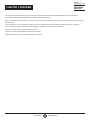
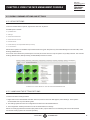
4. Click on the MCX ControllerSetup.exe file extracted previously. The MCX Controller Setup screen appears.
FIGURE 2-1. MCX CONTROLLER SETUP SCREEN
5. Select Yes to start setup. The License agreement page appears.

81. 8 7 7. 8 7 7. 2 2 6 9 BLACKBOX.COM
NEED HELP?
LEAVE THE TECH TO US
LIVE 24/7
TECHNICAL
SUPPORT
1.877.87 7. 2269
CHAPTER 2: INSTALLATION
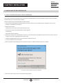
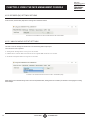
FIGURE 2-2. LICENSE AGREEMENT PAGE
6. Select “I accept the agreement” and press the Next button. The Select Install Directory screen appears.
7. Enter the location where you want to install the MCX Controller. Click on the Browse.. button if required.
FIGURE 2-3. INSTALLATION LOCATION

9
1. 8 7 7. 8 7 7. 2 2 6 9 BLACKBOX.COM
NEED HELP?
LEAVE THE TECH TO US
LIVE 24/7
TECHNICAL
SUPPORT
1.877.87 7. 2269
CHAPTER 2: INSTALLATION
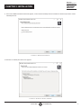
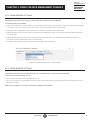
8. In the Select Additional Tasks window that appears, confirm Create a desktop shortcut checkbox is selected if you want to create
a desktop shortcut.
FIGURE 2-4. DESKTOP SHORTCUT
9. Click Next. The Ready to Install screen appears.
FIGURE 2-5. READY TO INSTALL SCREEN

10 1. 8 7 7. 8 7 7. 2 2 6 9 BLACKBOX.COM
NEED HELP?
LEAVE THE TECH TO US
LIVE 24/7
TECHNICAL
SUPPORT
1.877.87 7. 2269
CHAPTER 2: INSTALLATION
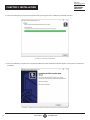
10. Click the Install button. A progress bar appears showing the progress of the installation of the MCX Controller.
FIGURE 2-6. INSTALLING SCREEN
11. Once the installation is complete, the Completing the MCX Controller Setup Wizard window appears. Click Finish to complete the
installation.
FIGURE 2-7. COMPLETING THE MCX CONTROLLER SETUP WIZARD SCREEN

11
1. 8 7 7. 8 7 7. 2 2 6 9 BLACKBOX.COM
NEED HELP?
LEAVE THE TECH TO US
LIVE 24/7
TECHNICAL
SUPPORT
1.877.87 7. 2269
CHAPTER 2: INSTALLATION
2.1.2 POINT-TO-POINT SETUP
An MCX S7 or S9 Encoder/Decoder pair (one transmitter and one receiver) can be connected directly in a point-to-point
configuration without the use of a network switch.
When set in point-to-point mode, all signals (video, audio, RS-232, IR, USB, etc.) are automatically paired by default for an MCX
hardware configuration.
To control and configure MCX devices in point-to-point mode:
1. Install the MCX Controller and MCX Controller Control Server on the same computer as outlined in the previous section.
2. Connect this computer to the 1-GbE interface port on either the transmitter (TX) or receiver (RX).
3. Then double-click the desktop shortcut, MCX Controller Launcher to launch the MCX Management Console and MCX Controller
Control Server.
4. Proceed to use the MCX Controller platform.
2.2 LAUNCHING THE MCX MANAGEMENT CONSOLE
To run the MCX Controller Server, start the executable file. Example screenshots shown next are running on Windows 10.
1. Launch the MCX Management Console using one of the options outlined below:
a. If the MCX Management Console was installed using the MCX Controller Evaluation package installer and the desktop shortcut
option selected, a MCX Management Console launch icon will be present on the Windows desktop.
Double-click the desktop icon and both the MCX Controller Server and MCX Management Console will automatically launch
simultaneously.
b. However, if the MCX Controller Control Server and the MCX Management Console were installed individually:
• Launch the MCX Controller Control Server (MCX Controller_control.exe) first.
• Then once the Control Server is running, launch the MCX Management Console (MCX Controller_manager.exe).
2. The MCX Management Console Graphical User Interface (GUI) loads.
3. Next detect all transmitter (TX) and receiver (RX) devices on the Network.
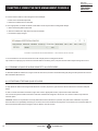
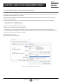
a. Enter the IP address of the computer hosting the MCX Controller Server in the field next to the IP address of MCX Controller
Server.
b. Click the Connect button, located beside the label IP address of MCX Controller Server.
NOTES:
i. If the Control Server is running on same computer as the MCX Controller client, it is possible to use the IP address 127.0.0.1,
which is the IPV4 loop-back address for ‘localhost’.
ii. Do not modify the default port number of 6970. The MCX Controller Server currently requires port 6970 as it only listens to this
port.

12 1. 8 7 7. 8 7 7. 2 2 6 9 BLACKBOX.COM
NEED HELP?
LEAVE THE TECH TO US
LIVE 24/7
TECHNICAL
SUPPORT
1.877.87 7. 2269
CHAPTER 2: INSTALLATION
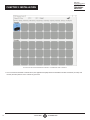
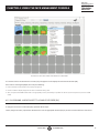
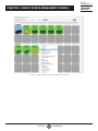
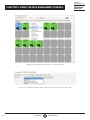
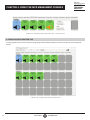
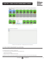
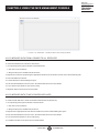
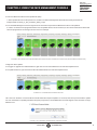
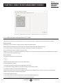
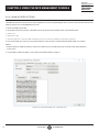
FIGURE 2-8. MCX MANAGEMENT CONSOLE IP ADDRESS AND CONNECT
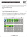
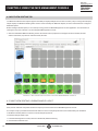
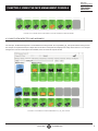
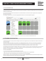
1. Once connected to the MCX Controller Server, the application displays all discovered MCX Controller transmitter (encoder) and
receiver (decoder) devices on the network as green tiles.

13
1. 8 7 7. 8 7 7. 2 2 6 9 BLACKBOX.COM
NEED HELP?
LEAVE THE TECH TO US
LIVE 24/7
TECHNICAL
SUPPORT
1.877.87 7. 2269
CHAPTER 2: INSTALLATION
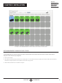
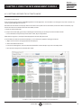
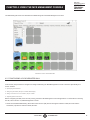
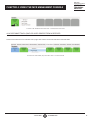
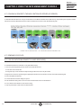
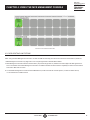
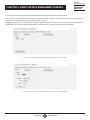
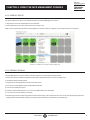
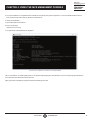
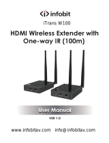
FIGURE 2-9. MCX MANAGEMENT CONSOLE DISPLAYING DETECTED DEVICES
MCX MANAGEMENT CONSOLE DEVICE STATUS
The MCX Management Console indicates the status of the decoders and encoders discovered on the network. Each status is
assigned a color code for easy recognition:
Green: Device active
Gray: Device previously discovered but not currently active. If in the device tab and an update file has been loaded, devices that are
detected as not appropriate for the update are also shown as gray tiles.
Yellow: Device booted from the Golden image file.

14 1. 8 7 7. 8 7 7. 2 2 6 9 BLACKBOX.COM
NEED HELP?
LEAVE THE TECH TO US
LIVE 24/7
TECHNICAL
SUPPORT
1.877.87 7. 2269
CHAPTER 3: MCX MANAGEMENT CONSOLE OVERVIEW
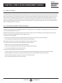
3.1 DATA ROUTING AND SWITCHING
The MCX Management Console application has a series of tabs that provide tools to control the various types of routing supported
by the MCX Controller platform, including:
Video (default)
Wall
Multiview
HDMI Audio
Single I2S Audio (Sometimes referred to as Analog audio.)
Quad I2S Audio
RS-232
Infrared (IR)
USB
An additional tab, the Device Management tab, is also provided.
When referring to video routing in relation to the MCX Controller platform, it means that the current video source displayed by a
Decoder (RX) device can be exchanged for another source coming from a different Encoder (TX) device.
MCX Controller video processing modes support the joining of multicast streams to support the requirements of Pro-AV
applications. A transmitter video stream is sent out in a multicast stream that the receiver subscribes to. When a source change is
requested, the receiver unsubscribes from the first transmitter’s stream and subscribes to the multicast stream of the transmitter
streaming the new source.
Video processing modes each have unique characteristics. For example, when a receiver is set in Genlock mode, the display
is genlocked to the source at zero-frame latency. When set in Fast Switch mode, the latency between the display and source is
between 1 and 2 video frames; however, switching between sources occurs seamlessly (instantaneous to the human eye).
Configuring and managing video modes is outlined in Section 4.1, Video Routing tab.
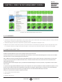
3.2 MCX MANAGEMENT CONSOLE INTERFACE
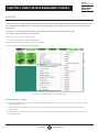
The MCX Management Console graphic interface is divided into sections:
The upper area of the user interface is labeled Decoders. All receiver (RX) devices detected on the network are displayed
in this section.
The lower area of the user interface is labeled Encoders. All transmitter (TX) devices detected on the network are displayed
in this section.
Each discovered Decoder and Encoder device is represented in the MCX Management Console by a green tile. In turn, each tile
provides helpful information specific to the individual device it represents.
Tile information displayed includes a device’s Hostname, IP Address and Firmware Version.
NOTE: The default Hostname assigned to an MCX Controller device is the device’s MAC address. This can be modified and the
change is persistent during power recycling, unless a factory reset is performed.
For details on managing the receiver (decoder) network settings, refer to Section 4.11.3.4, Decoder Network Interface Settings and
for the transmitter (encoder) network settings refer to Section 4.11.4.3, Encoder Network Interface Settings.
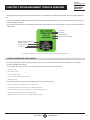
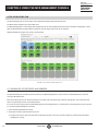
If a source device, such as a Blu-ray player, is connected to the HDMI Input port of an encoder (TX) device, a picture representing
the source appears within the associated tile. Additionally, data is provided regarding the HDMI stream. This includes the multicast
address used for streaming, the video resolution and the video color space information.

15
1. 8 7 7. 8 7 7. 2 2 6 9 BLACKBOX.COM
NEED HELP?
LEAVE THE TECH TO US
LIVE 24/7
TECHNICAL
SUPPORT
1.877.87 7. 2269
CHAPTER 3: MCX MANAGEMENT CONSOLE OVERVIEW
Similarly, if a display is connected to a decoder (RX) device, an illustration of a display appears within the corresponding decoder’s
tile.
If there is no illustration visible within a tile, this indicates that the MCX Controller device is detected but currently there is either no
source or display connected.
For receivers, the video mode is also displayed indicating the mode a device is currently operating in, such as Fast Switch, Genlock
or Wall mode.
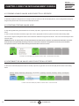
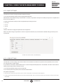
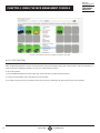
Multicast Streaming Address
Streaming Status
Video Resolution
Color Space
Host name
IP Address
Firmware Version
Current Video Mode (RX)
FIGURE 3-1. EXAMPLE OF DATA DISPLAYED FOR DECODER (RX) DEVICE TILE
3.3 MCX CONTROLLER VIDEO MODES
The Video Routing tab is used to set up and manage video routing. This tab is used to join decoder (RX) devices to a specific
encoder (TX) HDMI Video stream.
A decoder (RX) device can operate in one of the following five video modes as outlined below.
Genlock mode
Fast Switch mode
Genlock Scaler mode
Genlock and Fast Switch Wall modes
Multiview mode
For information about configuring and managing the processing modes, refer to:
Genlock mode: refer to Section 4.1.2, Genlock mode.
Fast Switch mode: refer to Section 4.1.3, Fast-Switch Mode.
Genlock Scaling mode: refer to Section 4.1.4, Genlock Scaling mode.
Wall mode: refer to Section 4.2, Wall Routing tab.
Multiview mode: refer to Section 5.3, Multiview Routing tab.

16 1. 8 7 7. 8 7 7. 2 2 6 9 BLACKBOX.COM
NEED HELP?
LEAVE THE TECH TO US
LIVE 24/7
TECHNICAL
SUPPORT
1.877.87 7. 2269
CHAPTER 3: MCX MANAGEMENT CONSOLE OVERVIEW
3.4 HDMI AUDIO ROUTING FROM THE MCX CONTROLLER
To allow for HDMI audio to be routed separately from the HDMI video, the audio data is extracted from the HDMI input on the
encoder (TX) side.
NOTE: The MCX Management Console automatically applies the split audio MCX Controller API command.
Exception to above: when a decoder (RX) is operating in Genlock mode, the audio follows the video and is always unchanged
regardless of the audio format (LPCM, Dolby, DTS, Stereo, Surround).
NOTES:
i. For MCX encoder (TX) devices, the original multichannel (up to 8 channels) audio and downmixed 2-channel (stereo) is sent to
subscribed decoder (RX) devices.
ii. For MCX encoder (TX) devices, if the HDMI audio received from the source is in LPCM format it is possible to “locally” breakout
the audio as downmixed 2-channel and then output as an additional audio stream.
iii. Decoder (RX) devices receiving HDMI audio can either:
a. Embed the audio into the HDMI output signal; or
b. Extract the audio over Quad I2S; or
c. Extract the downmixed audio version over Single I2S.
For more information about configuring and managing audio through the MCX Controller chipsets:
HDMI Audio routing: refer to Section 5.4, HDMI Audio Routing tab.
Single IS2 (Analog) Audio routing: refer to Section 5.5, Analog Audio Routing tab.
Quad IS2 Audio routing: refer to Section 5.6, I2S Audio Routing tab.
3.5 RS-232 AND INFRARED (IR) ROUTING
RS-232 and Infrared (IR) data is routed between encoders (TX) and decoders (RX) using Unicast or Broadcast protocols
when sending data to one or all devices respectively.
Unlike audio and video, where data is always routed from an encoder (TX) to one or more decoders (RX), transmitters (TX)
and receivers (RX) can both send and receive RS-232 and Infrared data. Therefore, all encoders (TX) and decoders (RX)
are shown as both Senders and Receivers.
When a Receiver is joined to a sender, a one-directional data tunnel is created.
To establish two-way RS-232 or IR communication, the devices must be joined twice, once as a sender and then again as a receiver.
NOTE: RS-232 and IR data transport is not limited to communication between devices only; it is also possible to inject RS-232
and IR data through the MCX Controller Server.
For details on configuring and managing:
RS-232 data routing: refer to Section 5.7, RS-232 Routing tab.
IR data routing: refer to Section 5.8, Infrared Routing tab.
3.6 USB 2.0 ROUTING
Routing of USB 2.0 data between encoders (TX) and decoders (RX) is done using USB over LAN chip technology. MCX eliminates
the USB’s 5-meter distance limitation, enabling applications where the host computer or USB device is required to be located away
from the user.
For details on configuring and managing USB routing, refer to Section 4.9, USB Routing tab.

17
1. 8 7 7. 8 7 7. 2 2 6 9 BLACKBOX.COM
NEED HELP?
LEAVE THE TECH TO US
LIVE 24/7
TECHNICAL
SUPPORT
1.877.87 7. 2269
CHAPTER 4: USING THE MCX MANAGMENT CONSOLE
4.1 VIDEO ROUTING TAB
The Video Routing tab is used to setup and manage Video/HDMI routing between the encoders (TX) and decoders (RX).
After connecting to the MCX Controller Control Server, the MCX Management Console by default loads the Video-Routing tab.
There are three (3) modes available for Video Routing:
Genlock
Fast Switch
Genlock Scaling
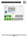
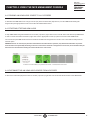
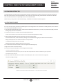
4.1.1 CONFIRMING WHICH ENCODERS ARE JOINED TO DECODERS
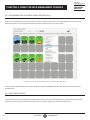
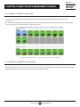
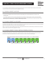
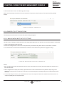
To verify which Decoders (RX) and Encoders (TX) are joined together, with the left mouse click on the decoder (RX) or encoder (TX)
tile it is desired to see the connection status for. All the associated “joined” tiles will be highlighted in orange.
The above functionality is enabled for each MCX Management Console tab, Video, Audio, RS-232, etc. For example, if Infrared
Routing tab selected the joined senders and receivers will be highlighted.
FIGURE 4-1. EXAMPLE OF DECODERS JOINED TO AN ENCODER

18 1. 8 7 7. 8 7 7. 2 2 6 9 BLACKBOX.COM
NEED HELP?
LEAVE THE TECH TO US
LIVE 24/7
TECHNICAL
SUPPORT
1.877.87 7. 2269
CHAPTER 4: USING THE MCX MANAGMENT CONSOLE
4.1.2 GENLOCK MODE
As mentioned earlier, the primary benefit of the Genlock mode is very low (zero-frame) latency between the source and the decoder.
When a decoder (RX) is set in Genlock mode, what is sent to the attached display is a byte-by-byte replication of what was received
from the source. The display is genlock to the source as if it is directly connected, making it the closest representation to a wire.
There is one exception to the above statement. If the input video bandwidth is too high to fit into the 10G network pipe, the video is
lightly compressed to allow the stream to fit into the 10G network pipe. An example of a signal that is over 10G is a UHD 60Hz with
full color sampling (RGB or YCbCr 444).
4.1.2.1 SETTING DECODER TO GENLOCK MODE
If not currently running, launch the MCX Management Console application. For information on starting the GUI, refer to section 4.5
Launching MCX Management Console.
Reminder: All discovered receiver (RX) devices are listed in the top half of under the header Decoder and all the transmitter (TX)
devices are listed on the bottom half under the header Encoder.
1. Select the Video Routing tab.
2. Verify if the Encoder (RX) (green tile) is indicating that the device(s) is currently set to the Genlock mode.
If it is indicated that it is presently in Genlock mode, skip to step 4 below.
NOTE: Refer to Figure 3-1, Example of data displayed for decoder (RX) device tile.
3. If Genlock is not currently the active mode, apply the setting as follows:
a. Right-mouse-click over the appropriate Decoder (RX) tile.
b. In the menu that appears under the Set Video Mode heading, select Genlock.
c. The decoder changes to the selected video mode.
4. Next, join the decoder (RX) to the encoder (TX).
a. In the Encoder section, select an encoder (TX) by clicking on its associated active (green) tile with left mouse button.
b. While holding down the left button, drag the encoder (TX) over the decoder (RX) tile it is to be joined with.
c. Release the mouse button to drop the encoder tile onto the decoder tile.
d. The encoder and decoder devices are now joined

19
1. 8 7 7. 8 7 7. 2 2 6 9 BLACKBOX.COM
NEED HELP?
LEAVE THE TECH TO US
LIVE 24/7
TECHNICAL
SUPPORT
1.877.87 7. 2269
CHAPTER 4: USING THE MCX MANAGMENT CONSOLE
FIGURE 4-2. APPLYING GENLOCK MODE TO A DECODER
5. The video source connected to the encoder (TX) now appears on the display connected to the decoder (RX).
If the video is not being displayed, then verify the following:
Ensure that the network switch is properly configured.
Confirm that the display supports the source resolution being sent.
Also, verify that the HDMI cable used is of high quality. This is particularly important for 4K 60 Hz, which requires a premium HDMI
cable.
4.1.2.2 ASSIGNING A NEW SOURCE TO A SINGLE DECODER (RX)
To assign a new source to a decoder (RX), repeat the above steps.
That is, drag the encoder (TX) with the desired source over the appropriate decoder (RX) to join the receiver itself to the new source.

20 1. 8 7 7. 8 7 7. 2 2 6 9 BLACKBOX.COM
NEED HELP?
LEAVE THE TECH TO US
LIVE 24/7
TECHNICAL
SUPPORT
1.877.87 7. 2269
CHAPTER 4: USING THE MCX MANAGMENT CONSOLE
4.1.2.3 SENDING A SINGLE SOURCE TO ONE OR MULTIPLE DECODERS
To feed the source of an encoder (TX) to one or more additional decoders (RX), drag and drop the encoder tile over each of the
decoder devices the source is desired to be output from.
The same source will then be displayed and visible on all the associated displays.
Remember that when in Genlock mode, since each of the decoder (RX) displays are synchronized to the source, they are all
synchronized to each other.
4.1.2.4 SENDING A SINGLE SOURCE TO ALL DECODERS
To send the same source to ALL decoders (RX), drag and drop the encoder (TX) that the desired source is connected to onto the blue
tile labeled All Displays. This tile is found in the Decoder section.
All the decoders (RX) will now be synchronized to the source and since in Genlock mode to each other.
4.1.2.5 STOPPING/STARTING VIDEO
To stop video being transmitted out of an encoder (TX), right-click over the appropriate encoder and select Stop Video.
To start or restart video transmission, right-click over the appropriate encoder (TX) and then select Start Video.
It is also possible to stop video and free the multicast IP addresses assigned to the streams. This is done with the Stop and Free
Channel option.
WARNING! If any decoders are currently subscribed to the multicast IP in question, they will remain subscribed. To prevent these
decoders from potentially streaming an incorrect source if the multicast is assigned to a new stream, we recommend that you
disconnect the decoder before freeing the channel. Refer to the next section.
Page is loading ...
Page is loading ...
Page is loading ...
Page is loading ...
Page is loading ...
Page is loading ...
Page is loading ...
Page is loading ...
Page is loading ...
Page is loading ...
Page is loading ...
Page is loading ...
Page is loading ...
Page is loading ...
Page is loading ...
Page is loading ...
Page is loading ...
Page is loading ...
Page is loading ...
Page is loading ...
Page is loading ...
Page is loading ...
Page is loading ...
Page is loading ...
Page is loading ...
Page is loading ...
Page is loading ...
Page is loading ...
Page is loading ...
Page is loading ...
Page is loading ...
Page is loading ...
Page is loading ...
Page is loading ...
Page is loading ...
Page is loading ...
Page is loading ...
Page is loading ...
Page is loading ...
Page is loading ...
Page is loading ...
Page is loading ...
Page is loading ...
Page is loading ...
Page is loading ...
Page is loading ...
Page is loading ...
Page is loading ...
Page is loading ...
Page is loading ...
Page is loading ...
Page is loading ...
Page is loading ...
Page is loading ...
Page is loading ...
Page is loading ...
Page is loading ...
Page is loading ...
Page is loading ...
Page is loading ...
Page is loading ...
Page is loading ...
Page is loading ...
Page is loading ...
Page is loading ...
Page is loading ...
Page is loading ...
Page is loading ...
-
 1
1
-
 2
2
-
 3
3
-
 4
4
-
 5
5
-
 6
6
-
 7
7
-
 8
8
-
 9
9
-
 10
10
-
 11
11
-
 12
12
-
 13
13
-
 14
14
-
 15
15
-
 16
16
-
 17
17
-
 18
18
-
 19
19
-
 20
20
-
 21
21
-
 22
22
-
 23
23
-
 24
24
-
 25
25
-
 26
26
-
 27
27
-
 28
28
-
 29
29
-
 30
30
-
 31
31
-
 32
32
-
 33
33
-
 34
34
-
 35
35
-
 36
36
-
 37
37
-
 38
38
-
 39
39
-
 40
40
-
 41
41
-
 42
42
-
 43
43
-
 44
44
-
 45
45
-
 46
46
-
 47
47
-
 48
48
-
 49
49
-
 50
50
-
 51
51
-
 52
52
-
 53
53
-
 54
54
-
 55
55
-
 56
56
-
 57
57
-
 58
58
-
 59
59
-
 60
60
-
 61
61
-
 62
62
-
 63
63
-
 64
64
-
 65
65
-
 66
66
-
 67
67
-
 68
68
-
 69
69
-
 70
70
-
 71
71
-
 72
72
-
 73
73
-
 74
74
-
 75
75
-
 76
76
-
 77
77
-
 78
78
-
 79
79
-
 80
80
-
 81
81
-
 82
82
-
 83
83
-
 84
84
-
 85
85
-
 86
86
-
 87
87
-
 88
88


Black Box MCX Management Controller Software Owner's manual
- Category
- Software
- Type
- Owner's manual
Ask a question and I''ll find the answer in the document
Finding information in a document is now easier with AI
Related papers
-
Black Box MCX Management Controller Software Owner's manual
-
-
-
-
-
-
Black Box ACU1700A User manual
-
-
-
Other documents
-
Value Wireless Audio/Video System, HDMI, 100 m User manual
-
infobit iSwitch 265 User manual
-
-
KEY DIGITAL APP READY Source and Display Control User manual
-
 Altimium ALT-IPD1080 User guide
-
VigilLink VL-IPHDKD-1 User manual
-
 LINK-MI LM-WH100 User manual
-
 infobit iTrans W100 User manual
-
 infobit iTrans W100 User manual
-
Yunzuo HY-HI3520-RJ45-200M User manual


