100
-
240
50/60 Hz
1.2A MAX.
1
2 3 4 5 6 7 8
2
1 2
3 4 5 6 7 8
1
2
1
INPUTS
OUTPUTS
R/R-Y
G/Y
VID
B/C
B-Y
H/HV
V
R/R-Y
G/Y
VID
B/C
B-Y
H/HV
V
PASS THRU
INPUTS
RESET
LAN
REMOTE
RS232/RS422
ACT
LINK
OUTPUT
VIDEO
SCALE
R
70-545-01
3
R/
R-Y
G/Y
B/
B-Y
H/
HV
V
OUTPUT
UNIV.
SCA
LER
70-544-01
5
R/
R-Y
G/Y
B/
B-Y
H/
HV
V
OUTPUT
PASS
THRU
70-547-01
8
R/
R-Y
G/Y
B/
B-Y
H/
HV
V
Extron
ISM 824
Integration Scaling
Multiswitcher
Align Output Card
with top & bottom
plastic guides.
R/
R-Y
G/Y
B/
B-Y
H/
HV
V
OUTPUT
7
SCAN
CON
V.
70-546-01
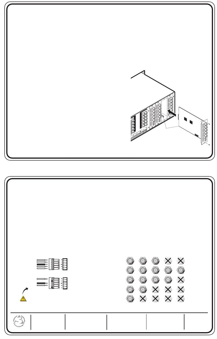
The Extron ISM 824 Output Card mounts in one of the four expansion slots at the rear of the ISM 824. The slots
are numbered 1 to 4 (see top of unit).
The Single Wideband, Universal Scaler, Video Scaler, and Scan Converter cards can be installed in any output
slot.
For full functionality the Dual Wideband card should be installed in slots 1 and 2 where dual outputs are
supported.
To install an output card in the ISM 824 base unit,
1.Turn off the ISM 824, and remove the power cord. Repeat for all connected devices.
2. At the rear, select an open slot, or take out the blank plate
from the desired output port by removing the two retaining
screws (top and bottom), and lifting the blank away.
N Re use the screws to secure the new output card in
place. Retain the blank plates. If a card is already
installed in the desired slot, remove the screws and
carefully pull the card out of the slot.
3. Remove the card from its outer box and anti-ESD bag,
holding the cards by the rear frame or BNC connectors.
4. With the card upright, align the front (non connector end)
of the card with the top and bottom plastic guides in the
ISM 824. Slide the card in carefully, keeping within the
guides. Push it home firmly, and secure it with the
retaining screws.
ISM 824 Output Card Installation Notes
Extron Electronics, USA
800.633.9876 714.491.1500
FAX 714.491.1517
Extron Electronics, Europe
+800.3987.6673 +31.33.453.4040
FAX +31.33.453.4050
Extron Electronics, Asia
+800.7339.8766 +65.6383.4400
FAX +65.6383.4664
Extron Electronics, Japan
+81.3.3511.7655
FAX +81.3.3511.7656
www.extron.com
68-1374-01
Rev. A
01 08
5. If applicable, repeat steps 2-4 for any other output cards.
6. Power on the ISM 824. The new output card(s) will be autodetected. The unit takes approximately
30 seconds to initialize a new card, and the front panel indicates the new card type and a counter,
counting down the initialization time. See inset for example display when a new Video Scaler card has
been installed in Slot #1.
7. Connect output devices to the video and audio connectors (see below) on the rear of the newly installed
cards. For Dual Wideband cards connect the HD-15 connectors to suitable display devices.
8. Power up the input devices and create the desired ties, following the steps given in chapter 3, “Operation
and Setup” of the ISM 824 User’s Manual.
9. Referring to the ISM 824 User’s Manual, configure the ISM 824 with the new cards, following the steps
given in chapter 3, “Operation and Setup”. Also see chapter 4, ”SIS Programming and Control”, chapter 5,
“ISM 824 Software”, and chapter 6, ”HTML Operation”, for alternative methods to configure the switcher.
ISM 824 Output Card Installation Notes, cont’d
Unbalanced Stereo Output
Tip
NO GROUND HERE.
Sleeve(s)
Tip
NO GROUND HERE.
Balanced Stereo Output
Tip
Ring
Sleeve(s)
Tip
Ring
L R
L R
Left
Right
Left
Right
CAUTION
For unbalanced audio, connect the sleeve(s)
to the center contact ground. DO NOT connect
the sleeve(s) to the negative (-) contacts.
H/HV
RGBHV
Video
RGsB or
Component
Video
S-Video Composite
Video
RGBS
Video
V
H/HV
V
H/HV
V
H/HV
V
H/HV
V
R/R-Y
G/Y
VID
B/C
B-Y
R/R-Y
G/Y
VID
B/C
B-Y
R/R-Y
G/Y
VID
B/C
B-Y
R/R-Y
G/Y
VID
B/C
B-Y
R/R-Y
G/Y
VID
B/C
B-Y