Page is loading ...

PORTATREE TIMING SYSTEMS, INC.
594 BLACKSTONE STREET – PO BOX 206
UXBRIDGE, MA 01569
TEL# 508-278-2199 ext: 508 FAX#508-278-5887
INSTALLATION PROCEDURE
1/4 & 1/8 MILE PERMANENT TRACK
1) Unpack all of the equipment and immediately inspect for shipping damage. Damages should be
immediately reported to the carrier and noted on the carriers receipt. Hidden damage should be
documented and shown to the carrier’s representative. Check the contents and match up to the invoice
and packing list.
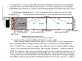
2) The first track function is to layout the track. The starting line should be selected and
temporarily marked. The starting line will consist of a pre-stage and stage infrared emitter/receiver
pair in both lanes. The pre-stage is 7 inches before the stage beam and whether or not a guard beam is
used, it is marked at 15 inches in front of the stage beam line. The guard beam location is the starting
line and all down track detector locations should be measured from the guard beam line.
3) The 60 foot mark and detector location should be measured from the guard beam mark - - 60 feet
-- or 61 feet 3 inches from the stage beam location. After laying out a temporary line at the 60 foot
location, you should square up the starting line and 60 foot location by measuring the diagonals.
4) When the starting line is permanently marked, you can then permanently mark the 60 foot
location and by measuring down each side of the track with the same measuring device, mark the 594
and 660 foot locations and the 1254 and 1320 foot locations. All measurements are from the guard
beam imaginary location or 15 inches in front of the stage beam location. We use roofing nails to
permanently mark the track surface.
5) After the entire track is permanently marked, you can begin locating the detectors, the yellow
banner emitter/receiver pairs will be used at the starting line - - pre-stage and stage. The reflector type
emitter/receiver in the same unit – SBL1) will be used at the 60 foot, mph, and finish locations.
6) All mounting stands and brackets should be made of very rigid material so as to resist vibration
and flexing. The starting line detectors will be mounted back to back with plenty of adjustment for
moving the detector up/down and left/right. The emitters and receivers on the outside of the track
should also have the same amount of adjustment.
7) The 60 foot banner SBL1 units must be mounted 6 inches off of the track surface as
recommended by the NHRA. If the track is hard hooking and you have a lot of vehicles that carry the
front tires past the 60 foot mark, the NHRA recommends 8 inches up to 12 inches off of the track.
8) The 60 foot detectors should be mounted at the edge of the track surface behind the guard
rail if you have one. Run a pull line tight across the track. The pull line should be 6 inches off of the
track surface all the way across the track surface. The center of the detection beam should be located on
the center of the pull line.
9) Perform the same beam location technique at all other down track locations. After all
detectors and mounts have been located, it is best to cement the bracket bases so that they do not move
in the ground.

10) The wiring of the track can now begin. There are two main cables that go to the starting line
and tree. They are completely pre-wired and connect to the interface box and junction box on the
starting line. Locate the interface box in the tower and run the main wire out to the center of the track.
The junction box has cables going to the respective pre-stage and stage emitters and receivers. All
connections are all labeled and can be routed to their respective detector and emitter location. The
Christmas tree can be moved at any desired location. It should be out at least 30 feet and many tracks
are now out 35 to 40 feet.
**Temporary Track – in lieu of a start line junction box, on temporary systems, we install additional
cable for start line infrareds and put a convolute plastic protection tube over the cables.
11) Next locate the mph junction boxes. These junction boxes should be located at the 1320 foot
locations and have enough wire to move them off the edge of the track. We have a 12 position terminal
strip inside which contains the wires for the mph and finish line detectors as well as the win light and
stop light for that lane.
Steps 12, 13, & 14 are prewired & precut on all temporary tracks.
12) There are two lengths of wire that will be used to reach the finish line on both sides of the track.
One length is (1550 on ¼ mile track or 850 on 1/8 mile track) for the far lane of the track. The other
cable (1450 feet on ¼ track or 750 on 1/8 mile track) is for the tower lane or near side of the track. Use
cable appropriately. Start with long run.
**Temporary Setups –Your cables have connectors with 2 pieces 1330 feet each on ¼ mile tracks or 2
pieces 665 feet each on 1/8 mile tracks. The remaining cable goes into your tower extension.
13) The junction box has a wiring schematic under the cover. The wires should be bared back
about ¾ inch twisted and folded over and twisted again and then soldered. Make the solder joint small
enough to get into the terminal strip and then fasten with the screw. The drain wire (bare wire) must be
attached to a separate terminal. At the finish line, you will need a relay to power your win lights and
stop light. It should not draw more than 40 milliamps at 12 volts. We have solid state relays that are
low powered. Run a wire out of the 1320 foot junction box to the relay where the win light is located.
Do not mount relay in the junction box.
**Temporary Tracks – Cabling is pre-wired**
14) The other end of each of these wires is to be terminated in the tower inside of the interface box.
Wiring is as follows:
Red and Blue Wire -- Positive 12 Volts D.C.
Black and White Wire -- Ground
Brown and Green Wire -- Signals – To Terminal Strip
Brown is MPH -- Green is Finish
Yellow Wire -- Negative 12 Volts D.C.
Orange Wire -- Win Light -- Terminal Strip
Note: The 60 foot wires require only 3 conductors. Red is positive, Black is ground, and the green
wire is the signal wire. It is probably prewired.
15) The Timeslip Printer can be located up to 8000 feet away and requires a 9 PIN SUB D
connector at each end . We usually prewire-or call Portatree for pinout specifications.

Note: Unless ordered, only a 6 foot cable is included with the printer.
16) Before connecting the computer, power up the interface box by connecting the red wire to
Positive and the brown wire to ground 12 Volts D.C., an AC to DC Converter can be used but it must
have a minimum of 2 amps of supply current. We recommend a well charged well maintained
automotive battery.
Note: 1) Do not power up the Portatree Professional Computer until all tree and track
connections are properly attached to the SUB D connectors.
2) Do not use the small transformer to power up the Portatree Professional in conjunction
with the interface box. The interface box will power up the Portatree Professional.
After powering up the interface box, you will have power to all of your detectors but the pre-stage and
stage lights on the Christmas Tree will not work until the computer is connected. You can align all of
the detectors by sweeping left/right and up/down. The Red L.E.D. will illuminate when the detector is
aligned. Read the literature on the banner units to efficiently align them. They may require sensitivity
adjustment. All reflector type banner units should be aligned on center of the target so that they will be
perfectly aligned. Half of the target should be able to be covered before the L.E.D. on the top of the unit
goes out. If the target has to fully be covered to make the L.E.D. go out then it is set too sensitive. It
must go out when half or a little more than half of the target is blocked. Adjustment can be made by
removing the adjustment access plug and turning the adjustment screw with a very small screwdriver.
18) The computer can be connected after the detectors are all working. Disconnect the 12 Volt
power to the interface box and then plug the two 25 PIN SUB D Connectors into their respective
positions. Power up the interface box. Read the manual and watch the video on the Portatree
Professional Computer operation. Set the computer accordingly. Press “C” for competition and the
stage lights on the tree will work.
19) Now the Starting Line can be set up using the pre-stage and stage lights on the Christmas
tree. Use the Portatree video to understand how rollout is set and build a rollout wheel to set the rollout.
After the rollout is set and the detectors are securely fastened, we must limit the field of vision of at least
the stage detectors so that unwanted reflections will not affect their performance. This is done by
locating 1 inch steel pipes - - 24 inches long between the stage detector and the emitter at the edge of the
track. Position the pipe so that the Red L.E.D. on back of the banner receiver stays on and is unaffected
by the pipe. Only the receivers need this protection. A bracket must be made to fix the pipe in position.
You can do the same to the pre-stage, but it is not necessary. In any event, you must keep the detectors
out of the direct sunlight and you must keep them out of heavy moisture conditions.
20) All detectors must have covers over them to keep them out of the weather and to keep the sun
from directly contacting them. The starting line takes a lot of time to set up correctly so you may want
to permanently fix them and place a rigid steel cover over them.
PLEASE BE VERY CAREFUL DURING INSTALLATION TO AVOID
LENGTHY TROUBLE SHOOTING.
IF YOU HAVE ANY QUESTIONS:
TEL# 508-278-2199 Ext: 508 or FAX# 278-5887
Email: [email protected]
/