Page is loading ...

© Copyright 2015, Capital Safety
Model Numbers: 8900298
USER INSTRUCTION RESCUE HOOK AND POLE
Form:5903794 Rev: B
The Ultimate in Fall Protection
This manual is intended to meet the Manufacturer’s Instructions as required by ANSI Z359.1-1992 and should be used as part
of an employee training program as required by OSHA.

WARNING: These instructions must be provided to the user of this equipment. The user must read and
understand these instructions before using this equipment. The user must follow the manufacturer’s
instructions for each component of the system. Manufacturer’s instructions must be followed for proper use and
maintenance of this equipment. Alterations or misuse of this equipment, or failure to follow instructions, may
result in serious injury or death.
WARNING: Always wear a hard hat when using the Rescue Hook and Pole.
IMPORTANT: If you have questions on the use, care, or suitability of this equipment for your application,
contact Capital Safety.
DESCRIPTIONS
8900298: Rescue hook and pole.
1.0 APPLICATIONS
1.1 PURPOSE: The Rescue Pole and Hook assists in the rescue of a suspended worker when used with another
rescue system or winch. The rescuer must be able to reach the suspended worker from above. It allows the
rescuer to attach a winch line or rescue lifeline to a dorsal D-ring of a suspended worker through the use of
a pole and hook.
2.0 SYSTEM REQUIREMENTS
2.1 ANCHORAGE STRENGTH: The anchorage to which the rescue lifeline is installed must meet the following
minimum strengths, according to your application:
RESCUE: Anchorages used for rescue applications must sustain static loads, applied in the directions allowed by
the rescue system, of at least 2,500 lbs.
3.0 OPERATION AND USE
WARNING: Do not alter or intentionally misuse this equipment. Consult with Capital Safety if using this
equipment in combination with components or subsystems other than those described in this manual. Some
subsystems and components combinations may interfere with the proper operation of this equipment.
WARNING: Do not use hook for fall arrest.
3.1 BEFORE EACH USE of this equipment, carefully inspect it to assure that it is in serviceable condition. Check
for worn or damaged parts. Inspect the hardware: ensure the snap hook and carabiners are not distorted or
have any sharp edges, burrs, cracks, or corrosion. Inspect other fall arrest equipment in accordance with the
manufacturer’s instructions supplied with each system component. Refer to Section 5.0 for further inspection
details. Do not use if inspection reveals an unsafe condition.
3.2 PLAN your rescue system before starting your work. Take into consideration factors affecting your safety at
any time during use. The following list gives some important points you must consider when planning your
system:
A. ANCHORAGE: Select an anchorage point that is rigid and capable of supporting the required loads. See
Section 2.1.
B. SHARP EDGES: Avoid working where the connecting subsystem (i.e. SRL, full body harness, lanyard,
lifeline, etc.) or other system components will be in contact with, or abrade against unprotected sharp
edges. If working with this equipment near sharp edges is unavoidable, protection against cutting must
be provided by using a heavy pad or other means over the exposed sharp edge.
C. ENVIRONMENTAL HAZARDS: Use of this equipment in areas where environmental hazards exist may
require additional precautions to reduce the possibility of injury to the user or damage to the equipment.
Hazards may include, but are not limited to; high heat, caustic chemicals, corrosive environments, high
voltage power lines, explosive or toxic gases, moving machinery, or sharp edges.
D. TRAINING: This equipment is intended to be used by persons trained in its correct application and use.

3.3 PROCEDURE:
The rescue procedure consists of the following steps:
Step 1. Connecting the snaphook to the top section of the rescue pole.
Step 2. Attaching the rescue lifeline to the captive eye of the snaphook. This connection is for rescue
only.
Step 3. Connecting the snaphook and rescue lifeline to the suspended worker’s harness.
Step 4. Raising or lowering the worker to a safe working level by using a winch or other rescue system.
3.4 USING THE RESCUE HOOK AND POLE:
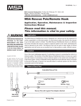
A. ATTACHING THE SNAP HOOK TO THE TOP SECTION OF THE POLE: Attach the snap hook to the top of
the pole by opening the gate of the hook, then slide the hook in. (See Figure 1).
Figure 1 - Attaching The Snaphook To The Top Section Of The Pole
Pole
Rescue Line
Hook

B. CONNECTING THE SNAPHOOK TO THE SUSPENDED WORKER’S HARNESS:
Step 1. Extend the pole to the required length.
Step 2. Place the snaphook onto the dorsal D-ring of the suspended worker’s harness.
WARNING: Hold the lifeline against the extension pole, with a small amount of tension, so that the snap hook
does not unintentionally detach and fall.
Step 3. To close the snap hook around the D-ring and release the snap hook from the pole, pull on the
pole. The snap hook should close over the D-ring and release from the pole. Tug on the lifeline to
ensure the snap hook is securely attached to the D-ring.
Step 4. Retract the pole to the minimum length. See Section 6.0 for cleaning and storage.
3.5 RESCUE:
A. Rescue Plan: A rescue plan must be in place before using the rescue hook and pole with a winch or other
rescue system.
WARNING: When raising a worker who is attached to a Self Retracting Lifeline (SRL), do not interfere with the
lifeline or hinder the working of the SRL. Do not disconnect the worker from the SRL or lanyard until they are
fully transferred over to the rescue device.
4.0 TRAINING
4.1 It is the responsibility of the user and purchaser of this equipment to be familiar with these instructions, and
are trained in the correct care and use, and are aware of the operating characteristics, application limits,
and the consequences of improper use of this equipment.
It is important to practice this rescue technique regularly to make sure that the team members have the
strength and ability to perform all the tasks required.
5.0 INSPECTION
5.1 BEFORE EACH USE inspect your rescue pole and hook according to Sections 5.2 and 5.3 of this manual.
A competent person, other than the user, must inspect this system at least annually. Record the results of
each inspection in the inspection and maintenance log in back of this manual.
WARNING: If subsystem components (tie-off adaptor, lifeline) have been subjected to the forces of a fall
arrest, remove from service and destroy.
5.2 INSPECTION STEPS:
Step 1. Inspect the snaphook. These items must not be damaged, broken or distorted. These items must
be free of sharp edges, burrs, cracks, worn parts, or corrosion. Hook gates must move freely and
lock upon closing.
Step 2. Inspect the rescue line for concentrated wear. Material must be free of frayed strands, broken
yarns, cuts, abrasions, burns, and discoloration. The line must be free of knots, excessive soiling,
paint build-up, and rust staining. Rope splices must be tight, with ve full tucks, and thimbles
must be held rmly by the splice. Check for chemical or heat damage; indicated by brown,
discolored, or brittle areas. Check for ultraviolet damage; indicated by discoloration and splinters
and slivers along the rope surface. All of the above factors are known to reduce line strength.
Damaged or questionable rope should be replaced.
Step 3. Inspect the top section of the pole. Inspect the rivets, frame for damage.
Step 4. Inspect the pole. The pole must extend and retract freely. The pole must be free of broken parts.
Step 5. Inspect all system components and subsystems according to manufacturer’s instructions.
Step 6. Inspect labels. All labels must be present and fully legible. See Section 8.0.
Step 7. Record the inspection results in the inspection and maintenance log in the back of this manual.
5.3 If inspection reveals an unsafe or defective condition, remove unit from service and contact an authorized
service center for repair.
IMPORTANT: Only Capital Safety or parties authorized in writing may make repairs to this equipment.

6.0 MAINTENANCE, SERVICING, STORAGE
6.1 CLEAN the rescue hook and connecting tool components with water and a mild detergent solution. Wipe
off hardware with a clean, dry cloth and hang to air dry. Do not force dry with heat. An excessive build-up
of paint, dirt, grease, etc. may prevent proper functioning of the system, and may weaken the system
components. If you have questions regarding the condition of your Rescue Kit system, or have doubt about
putting it into service, contact Capital Safety.
6.2 STORE the rescue connecting tool and hook system in a cool, dry, clean environment, out of direct sunlight.
Avoid areas where chemical vapors exist. Thoroughly inspect the rescue connecting tool and hook system
after extended storage.
7.0 SPECIFICATIONS
7.1 MATERIALS:
Pole: Stainless steel and steel.
Snap Hook: Aluminum and steel.
8.0 LABELING
8.1 The following labels must be present and fully legible:

INSPECTION AND MAINTENANCE LOG
SERIAL NUMBER:
MODEL NUMBER:
DATE PURCHASED: DATE OF FIRST USE:
INSPECTION DATE INSPECTION ITEMS
NOTED
CORRECTIVE ACTION MAINTENANCE
PERFORMED
Approved By:
Approved By:
Approved By:
Approved By:
Approved By:
Approved By:
Approved By:
Approved By:
Approved By:
Approved By:
Approved By:
Approved By:
Approved By:
Approved By:
Approved By:
Approved By:
Approved By:
Approved By:

ISO
9001
USA
3833 SALA Way
Red Wing, MN 55066-5005
Toll Free: 800.328.6146
Phone: 651.388.8282
Fax: 651.388.5065
solutions@capitalsafety.com
Brazil
Rua Anne Frank, 2621
Boqueirão Curitiba PR
81650-020
Brazil
Phone: 0800-942-2300
brasil@capitalsafety.com
Mexico
Calle Norte 35, 895-E
Col. Industrial Vallejo
C.P. 02300 Azcapotzalco
Mexico D.F.
Phone: (55) 57194820
mexico@capitalsafety.com
Colombia
Compañía Latinoamericana de Seguridad S.A.S.
Carrera 106 #15-25 Interior 105 Manzana 15
Zona Franca - Bogotá, Colombia
Phone: 57 1 6014777
servicioalcliente@capitalsafety.com
Canada
260 Export Boulevard
Mississauga, ON L5S 1Y9
Phone: 905.795.9333
Toll-Free: 800.387.7484
Fax: 888.387.7484
info.ca@capitalsafety.com
EMEA (Europe, Middle East, Africa)
EMEA Headquarters:
5a Merse Road
North Moons Moat
Redditch, Worcestershire
B98 9HL UK
Phone: + 44 (0)1527 548 000
Fax: + 44 (0)1527 591 000
csgne@capitalsafety.com
France:
Le Broc Center
Z.I. 1re Avenue - BP15
06511 Carros Le Broc Cedex
France
Phone: + 33 04 97 10 00 10
Fax: + 33 04 93 08 79 70
information@capitalsafety.com
Australia & New Zealand
95 Derby Street
Silverwater
Sydney NSW 2128
Australia
Phone: +(61) 2 8753 7600
Toll-Free : 1800 245 002 (AUS)
Toll-Free : 0800 212 505 (NZ)
Fax: +(61) 2 8753 7603
sales@capitalsafety.com.au
Asia
Singapore:
69, Ubi Road 1, #05-20
Oxley Bizhub
Singapore 408731
Phone: +65 - 65587758
Fax: +65 - 65587058
inquiry@capitalsafety.com
Shanghai:
Rm 1406, China Venturetech Plaza
819 Nan Jing Xi Rd,
Shanghai 200041, P R China
Phone: +86 21 62539050
Fax: +86 21 62539060
inquiry@capitalsafety.cn
www.capitalsafety.com
LIMITED LIFETIME WARRANTY
Warranty to End User: D B Industries, Inc., dba CAPITAL SAFETY USA (“CAPITAL SAFETY”)
warrants to the original end user (“End User”) that its products are free from defects in materials and
workmanship under normal use and service. This warranty extends for the lifetime of the product
from the date the product is purchased by the End User, in new and unused condition, from a CAPITAL
SAFETY authorized distributor. CAPITAL SAFETY’S entire liability to End User and End User’s exclusive
remedy under this warranty is limited to the repair or replacement in kind of any defective product
within its lifetime (as CAPITAL SAFETY in its sole discretion determines and deems appropriate). No oral
or written information or advice given by CAPITAL SAFETY, its distributors, directors, offi cers, agents
or employees shall create any different or additional warranties or in any way increase the scope of
this warranty. CAPITAL SAFETY will not accept liability for defects that are the result of product abuse,
misuse, alteration or modifi cation, or for defects that are due to a failure to install, maintain, or use the
product in accordance with the manufacturer’s instructions.
CAPITAL SAFETY’S WARRANTY APPLIES ONLY TO THE END USER. THIS WARRANTY IS THE ONLY
WARRANTY APPLICABLE TO OUR PRODUCTS AND IS IN LIEU OF ALL OTHER WARRANTIES AND
LIABILITIES, EXPRESSED OR IMPLIED. CAPITAL SAFETY EXPRESSLY EXCLUDES AND DISCLAIMS
ANY IMPLIED WARRANTIES OF MERCHANTABILITY OR FITNESS FOR A PARTICULAR PURPOSE, AND
SHALL NOT BE LIABLE FOR INCIDENTAL, PUNITIVE OR CONSEQUENTIAL DAMAGES OF ANY NATURE,
INCLUDING WITHOUT LIMITATION, LOST PROFITS, REVENUES, OR PRODUCTIVITY, OR FOR BODILY
INJURY OR DEATH OR LOSS OR DAMAGE TO PROPERTY, UNDER ANY THEORY OF LIABILITY, INCLUDING
WITHOUT LIMITATION, CONTRACT, WARRANTY, STRICT LIABILITY, TORT (INCLUDING NEGLIGENCE) OR
OTHER LEGAL OR EQUITABLE THEORY.
/