Page is loading ...

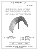
501-123 Half Moon Rung Climber Page 1
Rev: 08/18/2005
SportsPlay Equipment, Inc. 5642 Natural Bridge, St. Louis, MO 63120 314-389-4140
www.sportsplayinc.com
Please retain this instruction sheet in your files. It contains important
replacement parts information. All equipment should be installed in
accordance with these instructions.
It is important to use and maintain all public playground equipment properly.
Playground equipment, which is improperly maintained, can cause serious
injury. Periodical inspections, maintenance, repair and/or replacement of
damaged parts is necessary for safe operation of equipment and safety of
users. Resilient surfacing should be used under all playground equipment.
Appropriate publications, available at no charge, from the Consumer Product
Safety Commission, include “A Handbook for Public Playground Safety.” You
can receive your free copy by calling 1-301-504-7908
PACKING LIST HARDWARE BAG
1 CTN Hardware Box 4 196-807 3/8” x 3/8” Socket Set Screw
1 WF 503-123 Half Moon Rung Climber 1 416-350 3/16” Socket Key
4 503-124 Anchor
1 805-532 Warning Label
1 805-534 SportsPlay Label
1 Maintenance Checklist
1 CTN 1 WF TOTAL PCS = 1 SKID WT 285# CLASS 60
Climber is 6’ high from the top of the resilient
surfacing to the underside of the highest point. It is
9’2” wide on center and rungs are 22” wide on
center.

501-123 Half Moon Rung Climber Page 2
Rev: 08/18/2005
SportsPlay Equipment, Inc. 5642 Natural Bridge, St. Louis, MO 63120 314-389-4140
www.sportsplayinc.com
GENERAL USE/FALL ZONE & FOOTING RECOMMENDATIONS
Stationary and portable equipment – use/fall zones should extend a minimum of
6 feet in all directions from the perimeter of the equipment ground space.
This area should be covered with the required amount of resilient safety
surfacing material. For some equipment – use/fall zones can overlap. See
Consumer Product Safety Commission guidelines. Diameter and depth of
footings illustrated are satisfactory in most applications for pipe sizes up
to 2 3/8” diameter. Varying soil and climatic conditions may require deeper
and heavier footings in some areas. Check local building codes.
Permanent Installation: Upright Suggested Bracing Method
*If resilient surfacing is to be less than 12”, then additional pipe should
be put in concrete to maintain proper finish grade for equipment.
USE AREA & FOOTING LAYOUT:
9
’
2
”
22
”
Use/Fall: 13’10” deep x 21’2” wide

501-123 Half Moon Rung Climber Page 3
Rev: 08/18/2005
SportsPlay Equipment, Inc. 5642 Natural Bridge, St. Louis, MO 63120 314-389-4140
www.sportsplayinc.com
GENERAL ASSEMBLY INSTRUCTIONS
Check all parts and hardware with the packing list to be sure you have
received everything needed to assemble this product. Contact your local
distributor with notification of any missing or damaged parts. Contact must
be made within ten (10) days of receipt of your order.
Only hand-tighten nuts and bolts on initial assembly. Final tightening
should be done evenly after final assembly when unit has been plumbed and
leveled. After assembly is complete, any ends of bolts protruding beyond
nuts should be cut off and/or peened over to remove any sharp projections.
Go over entire unit to file smooth any sharp edges or projections that may
have been caused by rough handling in shipping or installation.
GENERAL MAINTENANCE INSTRUCTIONS
Check monthly for loose bolts, damaged or broken parts. Tighten and/or
replace immediately.
ASSEMBLY AND INSTALLATION:
NOTE: All threaded ends of bolts protruding beyond nuts must be cut off
and/or peened to eliminate sharp edges. No more than two threads
should extend beyond face of nut. All washers, “T” nuts, and other
fastener hardware used on round pipe or tubing must be hammered down
to conform to the curved underlying surface to eliminate catch
points. DO NOT tighten nuts more than hand-tight until entire
assembly is completed.
STEP #1: Lay out all parts in the desired location
STEP #2: Stand climber where you want to install it and mark the leg
positions according to the dimensions on page 1.
STEP #3: Dig holes 2’deep, install the sleeves in cement and brace, making
sure to keep distances accurate.
STEP #4: Let cement cure 48 hours.
STEP #5: Slip climber over the sleeves
STEP #6: Tighten set screws in weld nuts located at the bottom of the
climber.
STEP #7: Attach Warning Label and Manufacturer’s Identification Label to a
clean surface. The labels should be attached in a location where
they are clearly visible and legible and away from normal hand and
foot placement areas. The labels must be replaced if they become
illegible, destroyed or are missing. Contact your SportsPlay
distributor for replacement labels.
/
