Page is loading ...

301-133 GEO-DOME (Perm)
Page 1
Rev 4/19/10
SportsPlay Equipment, Inc., 5642 Natural Bridge, St. Louis, MO 63120 (314) 389-4140
www.sportsplayinc.com
IMPORTANT
PLEASE READ THESE INSTRUCTIONS BEFORE COMMENCING ASSEMBLY. Please retain this
instruction sheet in your files. It contains important replacement parts
information. All equipment must be installed in accordance with these
instructions. It is important to use and maintain all public playground
equipment properly. Playground equipment, which is improperly maintained, can
cause serious injury. Periodical inspections, maintenance, repair and/or
replacement of damaged parts is necessary for safe operation of equipment.
Appropriate publications, available at no charge, from the Consumer Product
Safety Commission, include “A Handbook for Public Playground Safety”. You can
receive your free copy by calling 1-301-504-7908.
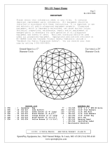
See page 4 for installation key
PACKING LIST
HARDWARE BAG
1
CTN
1
Hardware
Bag
26
116-545
5/16” x 2½” Button HD Bolts
5
503-647
Dome Anchors
62
316-501
5/16” Flat Washers
2
CTN
15
303-224
Braces (Blue)
31
216-501
5/16” Hex Nuts
1
CTN
20
303-221
Braces (Red)
26
326-501
5/16” Lock Washers
1
CTN
15
303-222
Braces (White)
1
416-350
Socket Key
1
805-532
Warning Label
1
805-534
SportsPlay Label
30
905-847
Bolt Caps
1
Maintenance Checklist
5 CTN 5 TOTAL PCS WT 130# CLASS 70
Dome footprint is
8’ wide
Dome use/fall zone is a
20’ diameter circle

301-133 GEO-DOME (Perm)
Page 2
Rev 4/19/10
SportsPlay Equipment, Inc., 5642 Natural Bridge, St. Louis, MO 63120 (314) 389-4140
www.sportsplayinc.com
GENERAL FOOTING RECOMMENDATIONS:
Diameter and depth of footings illustrated are satisfactory in most applications for
pipe size up to 1 1/4" in diameter. Varying soil and climate conditions may require
deeper and/or heavier footings in some areas. Check local building codes.
USE AREA AND FOOTING LAYOUT:
MAINTENANCE:
Periodically, check for loose bolts and worn or broken parts. Tighten loose bolts immediately.
If parts are worn or broken, discontinue use immediately and contact your SportsPlay distributor
for replacements.
GENERAL ASSEMBLY INSTRUCTIONS:
Check all the parts and hardware with the packing list to be sure you have received everything
needed to assemble this product.
Check each part carefully and remove any sharp edges or projections that may have been caused in
shipping. CONTACT YOUR LOCAL DISTRIBUTOR WITH NOTIFICATION OF ANY MISSING OR DAMAGED PARTS.
Contact must be made within ten days of receipt of your order.

301-133 GEO-DOME (Perm)
Page 3
Rev 4/19/10
SportsPlay Equipment, Inc., 5642 Natural Bridge, St. Louis, MO 63120 (314) 389-4140
www.sportsplayinc.com
SPECIFIC ASSEMBLY INSTRUCTIONS:
NOTE:
Extra long bolts are supplied to make assembly possible after assembly is complete, all
protruding threads must be cut off and peened over to remove any sharp projections.
Bolt Caps are also provided if you would like to use. These however, must be installed
before the nut is put on the bolt. They are two piece, and the cap can be placed on
after bolt is cut and peened over.
STEP #1:
Start with 303-222 White Braces. Assemble bottom row. At the footing marked with a
circle (see sketch pg. 1), use 116-545 2 ½” button head bolts inserted from the insid e
with one 316-501 Flat Washer on both sides and one 216-501 Hex Nut. On the other
bottom joints use one 116-545 2 ½” button head bolt inserted from the outside with one
316-501 flat washer under the head of the button head bolt, and one washer and one 326-
501 lock washer under a 216-501 5/16” hex nut. DO NOT TIGHTEN ANY NUTS MORE THAN A FEW
TURNS AT THIS POINT.
STEP #2:
Next assemble all the joints with five 303-224 Blue Braces, use one 116-545 5/16” x 2½”
button head bolt put thru from outside with one 316-501 flat washer under the head of
the button head bolt, and one flat washer and one lock washer under the hex nut. (See
Plan View Illustration for Color Code for Braces). Always position bars where ends
point up on bottom so that ends of bars pointing down are on top.
STEP #3:
Now assemble the six unit joints using the 2-1/2” button head bolts, with washers on
both ends and a lock washer under the hex nut.
STEP #4:
Continue this procedure for the final five brace connections at the top.
STEP #5:
Place a “C”-Clamp (or similar) over the joined braces and tighten down. NOW TIGHTEN ALL
JOINTS SECURELY. Then cut off all bolts ends so that no more than 2 threads extend
beyond the nut. Peen or file to remove sharp edges. Firmly press the Bolt Cover Lids
over the Bolt Caps.
STEP #6:
After assembly, locate the five footing holes as shown on the illustration on page 2.
Place a wood or metal stake at each hole location. Move Geo-Dome out of the way and
dig holes. (See Footing Diagram, p.2) Allow for proper depth of resilient surfacing.
STEP #7:
Reposition Geo-Dome and attach 503-637 Anchor as shown using washers on both sides of
the dome anchor and a lock washer under the hex nut. Pour concrete into holes and let
set for 48 hours. After concrete has hardened, the Geo-Dome is ready to use.
STEP #8:
Attach Warning Label and Manufacturer’s Identification Label to a clean surface. The
Labels should be attached in a location where they are clearly visible and legible and
away from normal hand and foot placement areas. The Labels must be replaced if they
become illegible, destroyed, or removed. Contact your Distributor for replacement
Labels.

301-133 GEO-DOME (Perm)
Page 4
Rev 4/19/10
SportsPlay Equipment, Inc., 5642 Natural Bridge, St. Louis, MO 63120 (314) 389-4140
www.sportsplayinc.com
Installation Key
# Boxes
BOX WEIGHT
BOX DIMENSIONS
2
28 LB.
30” X 7” X 5”
1
32 LB
33” X 7” X 5”
1
40 LB.
32.5” X 7” X 5”
1
11 LB
23.5” X 7” X 5”
/
