Page is loading ...

INSTRUCTIONS FOR USE
IMPORTANT: Read completely
before charging
MODE D’EMPLOI
IMPORTANT: à lire avant
d’utiliser l’appareil
MODO DE EMPLEO
IMPORTANTE: a leer antes de
utilizar el aparato
Automatic charger for 12V lead/acid batteries
Chargeur automatique pour batteries 12V plomb-acide
Cargador automático para baterías 12V plomo-ácido •
4 x 12V
STD / AGM-MF / GEL
2 - 40Ah (charge within 12 hours)
NEW battry initialization - 1 hour
+ -
MODEL: TS-52, 53, 54
AC: 115 / 230 / 240VAC 50-60Hz
414VA (3.6A @ 115V / 1,8A @ 240V)
DC: Max. 4A @ 12V (per circuit)
Thermally adjusted
ANWENDUNGSVORSCHRIFTEN
WICHTIG: Vollständig vor der
Benutzung lesen
GEBRUIKSAANWIJZING
BELANGRIJK: Lees volledig voor
gebruik
MODO DE EMPLEO
IMPORTANTE: a leer antes de
utilizar el aparato
ISTRUZIONI PER L’USO
IMPORTANTE: da leggere prima
di utilizzare l’apparecchio

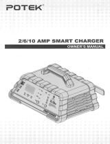
LED indications (illustration 1)
NEWNEWNEW
AGM STD
444
2
2
2
NEW
2 AMP
4 AMP
CHARGESAVE
LED #1 LED #7
LED #2 LED #8
LED #3 LED #9
LED #5 LED #6
LED #1: switch NEW selected, to initialize new batteries
LED #2: switch 2 AMP selected, charge at 2 Amps
LED #3: switch 4 AMP selected, charge at 4 Amps
Note: when neither LED #1 nor #2, #3 are on, the connection to the battery is incorrect.
Check if the cables are well connected. Reverse the polarity of the clamps if neccessary.
LED #5: DESULFATION, the charger is recovering the battery
LED #6: CHARGING
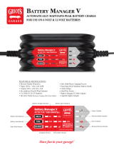
LED #7, #8, #9: Test results, see illustration 2
Early warning of battery problems / Avertissement anticipé des problèmes de
batterie (illustration 2)
TEST
VOLTS 0 12.2 12.4 12.5 12.7
STD
GEL
AGM / MF
61-80%
40-60% 61-80%
61-80%
61-80%
61-80%
61-80%
40-60%
40-60%
MOUNTING NOTICE
NOTICE DE MONTAGE
NOTA PARA EL MONTAJE
WANDMONTIERUNG
MUURBEVESTIGING
NOTA DI MONTAGGIO

3
IMPORTANT SAFETY INSTRUCTIONS FOR CANADA & USA
THIS PORTION OF THE MANUAL CONTAINS IMPORTANT SAFETY INSTRUCTIONS FOR
THE OPTIMATE PRO BATTERY CHARGER. IT IS OF THE UTMOST IMPORTANCE THAT
EACH TIME, BEFORE USING THE CHARGER, YOU READ AND EXACTLY FOLLOW THESE
INSTRUCTIONS. SAVE THESE INSTRUCTIONS.
AUTOMATIC CHARGER FOR 12V LEAD-ACID BATTERIES
DO NOT USE FOR NiCd, NiMH, Li-Ion OR NON-RECHARGEABLE BATTERIES.
1. CAUTION : CLASS I APPLIANCE. REQUIRES A GROUND CONNECTION.
2. Do not expose charger to rain or snow.
3. Use of an attachment not recommended or sold by the battery charger manufacturer may result in a risk of fire, electric shock,or injury to
persons.
4. To reduce risk of damage to electric plug and cord,pull by plug rather than cord when disconnecting charger.
5. An extension cord should not be used unless absolutely necessary. Use of improper extension cord could result
in a risk of fire and electric shock.If extension cord must be used make sure that :
a) pins on plug of extension cord are the same number, size and shape as those of plug on charger.
b) the extension cord is property wired and in good electrical condition,and
c) the conductor wire size is large enough for the AC ampere rating of the charger as specified in the table below.
AC INPUT RATING IN AMPERES
Equal to or greater than But less than
LENGTH OF CORD,
FEET (m)
AWG SIZE
OF CORD
2A 3A 25 (17.6)
50 (15.2)
100 (30.5)
18
18
14
6. Do not operate charger with damaged cord or plug - replace the cord or plug immediately.
7. Do not operate charger if it has received a sharp blow, been dropped,or otherwise damaged in any way; take it
to a qualified serviceman.
8. Do not disassemble charger; take it to a qualified serviceman when service or repair is required.
Incorrect reassembly may result in a risk of electric shock or fire.
9. To reduce risk of electric shock, unplug the charger from outlet before attempting any maintenance or cleaning.
Turning off controls will not reduce this risk.Clean only with slightly moist,not wet, cloth.Do not use solvents.
10. WARNING - RISK OF EXPLOSIVE GASES.
a) WORKING IN VICINITY OF A LEAD-ACID BATTERY IS DANGEROUS. B ATTERIES GENERATE EXPLOSIVE GASES
DURING NORMAL BATTERY OPERATION. FOR THIS REASON, IT IS OF UTMOST IMPORTANCE THAT YOU FOLLOW THE
INSTRUCTIONS EACH TIME YOU USE THE CHARGER.
b) To reduce risk of battery explosion,follow these instructions and those published by the battery manufacturer
and manufacturer of any equipment you intend to use in vicinity of the battery. Review cautionary marking on
these products and on engine.
11. PERSONAL PRECAUTIONS.
a) Someone should be within range of your voice OR close enough to come to your aid when you work near a lead-acid battery.
b) Have plenty of fresh water and soap nearby in case battery acid contacts skin, clothing or eyes.
c) Wear complete eye protection and clothing protection. Avoid touching eyes while working near battery.
d) If battery acid contacts or enters eye, flood eye with cold running water for at least 10 minutes and get medical
attention immediately. If battery acid contacts skin or clothing, wash immediately with soap and water. If acid enters
an eye , immediately flood eye with running cold water for at least 10 minutes and get medical attention immediately.
e) NEVER smoke or allow a spark or flame in vicinity of battery or engine.
f) Be extra cautious to reduce risk of dropping a metal tool onto battery. It might spark or short-circuit battery or other electrical part
that may cause explosion.
g) Remove personal metal items such as rings, bracelets ,necklaces , and watches when working with a lead-acid
battery. A lead-acid battery can produce a short-circuit current high enough to weld a ring or the like to metal,
causing a severe burn.
i) NEVER charge a frozen battery.
IMPORTANT SAFETY INSTRUCTIONS - READ EACH TIME BEFORE USING THE CHARGER

4
12. PREPARING TO CHARGE
a) If necessary to remove battery from vehicle to charge, always remove grounded terminal from battery first.
Make sure all accessories in the vehicle are off, so as not to cause an arc.
b) Be sure area around battery is well ventilated while battery is being charged. Gas can be forcefully blown away
by using a piece of cardboard or other non-metallic material as a fan.
c) Clean battery terminals.Be careful to keep corrosion from coming in contact with eyes.
d) Add distilled water in each cell until battery acid reaches level specified by battery manufacturer. This helps purge
excessive gas from cells. Do not overfill. For a battery without cell caps, such as valve regulated lead acid (VRLA) or absorbed glass
mat (AGM) batteries, carefully follow manufacturer’s recharging instructions.
e) Study all battery manufacturer’s specific precautions such as removing or not removing cell caps while charging
and recommended rates of charge.
f) Determine voltage of battery by referring to vehicle or other user’s manual and BEFORE MAKING THE BATTERY
CONNECTIONS , MAKE SURE TH AT THE VOLTAGE OF THE BATTERY YOU ARE GOING TO CHARGE MATCHES THE
OUTPUT VOLTAGE OF THE CHARGER.
13. CHARGER LOCATION.
a) Locate charger as far away from battery as DC cables permit.
b) Never place charger directly above battery being charged; gases from battery will corrode and damage the charger. c) Never allow
battery acid to drip on charger when reading gravity or filling battery.
Do not operate charger in a closed-in area or restrict ventilation in any way.
d) Do not set a battery on top of charger. IMPORTANT : Place charger on a hard flat surface or mount onto a vertical surface. Do not
place on plastic, leather or textile surface.
IMPORTANT: EXPOSURE TO LIQUIDS: Failure of the charger due to oxidation resulting from the eventual penetration of
corrosive liquid into the electronic components, connectors or plugs,is not covered by warranty.
14. DC CONNECTION PRECAUTIONS
a) Connect and disconnect DC output clips only after setting any charger switches to off position and removing AC
cord from electric outlet. Never allow clips to touch each other, however should this happen when not connected to a battery no
damage will result to the charger circuit & the automatic charging programme will reset to «start».
b) Attach clips to battery and chassis as indicated in 15(e), 15(f), and 16(b) through 16(d).
NOTE : This battery charger has an automatic safety feature that will prevent it from operating if the battery has been inversely
connected. Set charger switches to off position and/or remove AC cord from electrical outlet, disconnect the battery clips, then
reconnect correctly according to the instructions below.
15. FOLLOW THESE STEPS WHEN BATTERY IS INSTALLED IN VEHICLE. A SPARK NEAR A BATTERY MAY CAUSE BATTERY
EXPLOSION. TO REDUCE RISK OF A SPARK NEAR BATTERY :
a) Position AC and DC cords so as to reduce risk of damage by hood, door or moving engine part.
b) Stay clear of fan -blades, belts,pulleys,and other parts that can cause injury to persons.
c) Check polarity of battery posts.POSITIVE (POS, P, +) battery post usually has larger diameter than NEGATIVE (NEG,
N,–) post.
d) Determine which post of battery is grounded (connected) to the chassis. If negative post is grounded to chassis
(as in most vehicles),see (e). If positive post is grounded to the chassis,see (f).
e) For negative-grounded vehicle, connect POSITIVE (RED) clip from battery charger to POSITIVE (POS, P, + )
ungrounded post of battery. Connect NEGATIVE (BLACK) clip to vehicle chassis or engine block away from battery.
Do not connect clip to carburetor, fuel lines, or sheet-metal body parts. Connect to a heavy gage metal part of the
frame or engine block.
f) For positive-grounded vehicle, connect NEGATIVE (BLACK) clip from battery charger to NEGATIVE (NEG. N , -)
ungrounded post of battery. Connect POSITIVE (RED) clip to vehicle chassis or engine block away from battery. Do
not connect clip to carburetor, fuel lines, or sheet-metal body parts. Connect to a heavy gage metal part of the
frame or engine block.
g) When disconnecting charger, turn switches to off, disconnect AC cord,remove clip from vehicle chassis,and then
remove clip from battery terminal.
h) See operating instructions for length of charge information.
16. FOLLOW THESE STEPS WHEN BATTERY IS OUTSIDE VEHICLE. A SPARK NEAR THE BATTERY MAY CAUSE BATTERY
EXPLOSION. TO REDUCE RISK OF A SPARK NEAR BATTERY :
a) Check polarity of battery posts. POSITIVE (POS, P, +) battery post usually has a larger diameter than NEGATIVE
(NEG,N, -) post.
b) This battery charger has an automatic safety feature that will prevent it from operating if the battery has been inversely
connected. The charger does not allow charge current unless a stable voltage of at least 2V is sensed.
c) Connect POSITIVE (RED) charger clip to POSITIVE (POS, P, +) post of battery.
d) Connect NEGATIVE (BLACK) charger clip to NEGATIVE (NEG, N, -) battery post of the battery.
e) Do not face battery when making final connection.
f) When disconnecting charger, always do so in reverse sequence of connecting procedure & break first connection
while as far away from battery as practical.
g) A marine (boat) battery must be removed & charged on shore. To charge it on board requires equipment specially
designed for marine use.
17. CHARGING OF IDENTICAL 12V BATTERIES CONNECTED IN SERIES : The OptiMate PRO4 model can be used to
charge 12V batteries connected in series, without delinking the positive post of the one battery from the negative post of the
IMPORTANT SAFETY INSTRUCTIONS - READ EACH TIME BEFORE USING THE CHARGER

5
other. Set the power ON/OFF switch to OFF position or remove the AC cord from the electric outlet. Connect the negative (black)
clamp and positive (red) clamp of one of the outputs to the negative (– /black) and positive (+/red) posts, and likewise the
clamps of the second output to the respective posts of the second battery, the clamps of the third output to the respective posts
of the third battery and the clamps of the fourth output to the respective posts of the fourth battery.
18. IF THE BATTERY IS DEEPLY DISCHARGED (AND POSSIBLY SULPHATED), REMOVE FROM THE VEHICLE and inspect the
battery before connecting the charger as indicated in 16(a) through 16(d). Visually check the battery for mechanical defects
such as a bulging or cracked casing, or signs of electrolyte leakage. If the battery has filler caps and the plates within the cells
can be seen from the outside, examine the battery carefully to try to determine if any cells seem different to the others (for
example, with white matter between the plates, plates touching). If mechanical defects have been found do not attempt to
charge, have battery professionally assessed.
19. IF THE BATTERY IS NEW, before connecting the charger read the battery manufacturer’s safety and operational
instructions carefully. If applicable, carefully and exactly follow acid filling instructions.
20. This appliance is not intended for use by persons (including children) with reduced physical, sensory or
mental capabilities, or lack of experience and knowledge, unless they have been given supervision or
instruction concerning use of the appliance by a person responsible for their safety. Children should be
supervised to ensure that they do not play with the appliance.
USING THE OPTIMATE PRO4 (OR PRO-S)
SAFETY WARNING AND NOTES: IF YOU HAVE NOT YET DONE SO, READ THE PRECEDING
PAGES LABELLED "IMPORTANT SAFETY INSTRUCTIONS" BEFORE OPERATING THIS CHARGER.
DISCONNECTION FROM THE BATTERY AND RESETTING THE CHARGE AND TEST CYCLE
It is a legally required safety recommendation that you do not make or break connections directly at the battery posts with the
charger powered up. Switch off the AC mains at the switch located at the back of the charger before removing the clips from
the battery posts. If the AC switch is toggled to ON position all CHARGE and TEST LEDs (LED #5 to 9) will flash twice to confirm
micro processor health, irrespective if the charger remains connected to a battery or not.
The following actions will also reset the charge and test program without breaking connections at the battery:
1. Toggle the AC switch to OFF position, wait for the all LEDs to go out, then toggle the switch to ON position.
2. Disconnect the charge cable at the connector closest to the charger, wait till the charge and test status LEDs flash twice to
confirm reset, and then reconnect.
3. If the charge selection is toggled between NEW and 2/4A the program will reset and the newly selected program will
continue.
IMPORTANT SWITCH SELECTIONS PRIOR TO USING THE CHARGER: PROGRAM OUTLINE
Input voltage selection for 115 / 230 / 240 Volts : Make sure the input voltage setting is correct for your AC electrical
supply before use.
CONNECTION TO THE INPUT (WALL SOCKET) AND SWITCHING ON THE CHARGER: Attach the power cord to the charger via
the power receptacle at the back of the charger, and insert the power plug into the wall socket (and switch on the socket
outlet if applicable). The charger’s on-off switch is located at the back of the charger.
OUTPUT PROGRAM SELECTION: Make the appropriate output selection before charging. The NEW LED #1, 2A LED #2 or 4A
LED #3 will indicate the chosen selection once the charger is powered up.
NEW - Select for the first activating charge of a new battery and before installing into a vehicle. The NEW program
(LED#1) disables recovery charge and limits charging to 60 minutes. Testing is also limited to a single 10 minute period after
which the MAINTENANCE CHARGE CYCLE continues until the battery is disconnected.
2A / 4A - for used batteries (or new batteries that may have been stored for extensive periods following activation)
Select the appropriate maximum charge current (2 / 4A) from the table on the front of the charger’s enclosure. The 2A / 4A
program limits charging to 12 hours for charge stages indicated by LED #5 and #6. Thereafter the voltage retention tests
and battery maintenance charging (LED #7,8,9) program continues until the battery is disconnected.
PROCEEDING TO CHARGE
The LED indicators (illustration 1 on page 2) are sequenced as they may come on through the course of the program. .
LEDs #1, or 2, or 3, will indicate according to the selected program. LED #1 = NEW / LED #2 = 2A max. / LED #3 = 4A max.
The program LEDs #1, or 2, or 3 will not indicate if:
a) the battery connections are inverted. No charge or test status LEDs will light following the micro processor health
confirmation. The charger is automatically protected against this error and no damage will result. Disconnect at the battery and
reconnect correctly. For OptiMate PRO-S only: The inverse polarity LED #4 will light, LED #1 / 2 / 3 remains on.
b) the charging circuit has failed. Repairs can only be done by qualified personnel. Please contact TecMate or their appointed agent.
USING THE OPTIMATE PRO

6
NEW BATTERY PROGRAM (1 HOUR):
PRE-QUALIFICATION TEST: RED LED #9 flashing
The battery voltage is below 12V which is not expected for a new dry charged battery recently filled with acid according to the
manufacturers instructions and the acid was allowed to settle for at least 60 minutes before connection to the charger; the
battery may have fatal damage such as a shorted cell. DO NOT CHARGE OR USE THE BATTERY.
For a new factory activated AGM or GEL that may have lost charge during extended storage, select the 2A or 4A program
according to the battery parameters and try again.
RECOVERY / DESULPHATE: LED #5
This mode is disabled for NEW batteries.
CHARGE: LED #6
BULK charge - LED #6 steady on: The ampmatic™ charge current monitoring and control mode automatically determines the
most efficient rate of charge current for the connected battery, according to its state of charge, state of health, and electrical
storage capacity. The delivered current may be anywhere from 0.4A to 4A.
FINAL charge - LED #6 flashing: The FINAL CHARGE mode starts when the voltage has reached 14.3V for the first time
during BULK CHARGE stage.
Pulsed equalization step: If the battery has accepted as much charge as its basic condition allows the ampmatic™ current
control circuit now delivers pulses of current for 10 minutes so as to cause the battery voltage to vary between 13.7V and 14.3V,
to equalise the individual cells within the battery.
Verification step: The battery's charge level is verified. If the battery requires further charging the program will revert to pulsed
equalization.
NOTE: For safety reasons there is an overall charge time limit of 1 hour.
VOLTAGE RETENTION TEST: LED #7 flashing
Delivery of current to the battery is interrupted for 10 minutes to allow the program to determine the battery's ability to retain
charge. A small load is applied to remove surface charge and improve test result accuracy.For batteries with a good state of
health LED #7 (green) should continue to flash for the full period.
Consult the “EARLY WARNING OF BATTERY PROBLEMS” table on page 2 for LED indications other than LED #7 (green).
A significant problem exists if the battery is unable to retain sufficient charge during the 12 hour test period. Read the section
NOTES ON TEST RESULTS on reasons for poor test results or how to test a battery that returns a good result but cannot deliver
sufficient power once it is returned to service.
MAINTENANCE CHARGE: LED #7 /8 / 9 steady on
The circuit offers current to the battery within a safe 13.6V voltage limit whilst the result of the voltage retention test is displayed.
Consult the “EARLY WARNING OF BATTERY PROBLEMS” table on page 2 for LED indications other than LED #7 (green).
A more detailed description of the automatic maintenance cycle for long term battery storage can be found under the section
AUTOMATIC BATTERY MAINTENANCE.
2A / 4A PROGRAM for USED / NEGLECTED batteries:
(or NEW batteries that may have been stored for extensive periods following initial activation):
VERY FLAT NEGLECTED BATTERIES: If the battery is deeply discharged (and possibly sulfated), remove from the
vehicle or equipment and inspect the battery before connecting the charger for a recovery attempt.
Pay particularly close attention to the following A battery left deep-discharged for an extended period may develop permanent
damage in one or more cells. Such batteries may heat up excessively during high current charging.
Monitor the battery temperature during the first hour, then hourly there-after. Check for unusual signs, such as bubbling or leaking
electrolyte, heightened activity in one cell compared to others, or hissing sounds. If at any time the battery is uncomfortably hot to
touch or you notice any unusual signs, DISCONNECT THE CHARGER IMMEDIATELY.
NOTE: The charger’s TURBO recovery mode cannot engage if it senses that the battery is still connected to a circuit which
effectively offers a lower electrical resistance than the battery on its own. However, if the deep-discharged battery is not removed
for recovery, neither battery nor vehicle or equipment electronics will be damaged.

7
PRE-QUALIFICATION TEST: LED #7 / 8 / 9
TEST LEDs #7/8/9 indicate the condition of the battery prior to charging. Charging commences after 10 seconds.
Consult the “EARLY WARNING OF BATTERY PROBLEMS” table on page 2 (illustration 2) for TEST LED indications.
LED #9 (red) flashing: The OptiMate PRO is injecting a test signal to see if the battery is recoverable. Once the indication
becomes steady for up to 10 seconds charging will commence. If after 5 minutes the flashing changes to double pulse
mode(-- -- --) the battery cannot be recovered.
RECOVERY / DESULPHATE: LED #5
This mode engages if during pre-qualification LED #9 (red) or LED #8 (yellow) or both indicated. The program will determine the
correct charge mode. Charge time: Minimum 15 minutes, maximum 2 hours.
TURBO recovery for very badly neglected batteries - LED #5 flashing (- - - - - ): Output voltage increases to a maximum of
22V with current limited to 0.2A. A battery able to recover will proceeed to PULSE recovery.
PULSE recovery - 15 minutes - LED #5 steady on: For a battery below 12.4V current is delivered in pulses during which the
battery is also tested for a short circuit cell condition.
If after 15 minutes the voltage fails to rise normally, no further charge current will be offered to the battery, as it is highly likely
that a severe short-circuit of negative and positive plates exists in more than one of the battery cells. The RED TEST LED (#9)
flashing in double pulse mode (-- -- --) indicates that charging has been interrupted.
For a battery responding as expected current is delivered in pulses to prepare the battery to accept normal charge.
CHARGE: LED #6
BULK charge - LED #6 steady on: The ampmatic™ charge current monitoring and control mode automatically determines the
most efficient rate of charge current for the connected battery, according to its state of charge, state of health, and electrical
storage capacity. The delivered current may be anywhere from 0.4A to 4A (2A program: 0.2 to 2A).
FINAL charge - LED #6 flashing: The FINAL CHARGE mode starts when the voltage has reached 14.3V for the first time
during BULK CHARGE stage.
Pulsed equalization step: If the battery has accepted as much charge as its basic condition allows the ampmatic™ current
control circuit now delivers pulses of current for 10 minutes so as to cause the battery voltage to vary between 13.7V and 14.3V,
to equalise the individual cells within the battery.
Verification step: The battery's charge level is verified. If the battery requires further charging the program will revert to pulsed
equalization.
NOTE: For safety reasons there is an overall charge time limit of 12 hours.
VOLTAGE RETENTION TEST: LED #7 flashing
Delivery of current to the battery is interrupted for 12 hours to allow the program to determine the battery's ability to retain
charge. A small load is applied to remove surface charge and improve test result accuracy. For batteries with a good state of
health LED #7 (green) should continue to flash for the full period.
Consult the “EARLY WARNING OF BATTERY PROBLEMS” table on page 2 for LED indications other than LED #7 (green).
A significant problem exists if the battery is unable to retain sufficient charge during the 12 hour test period.
Read the section NOTES ON TEST RESULTS for automatic repeat testing, or reasons for poor test results or how to test a battery
that returns a good result but cannot deliver sufficient power once it is returned to service.
MAINTENANCE CHARGE: LED #7 /8 / 9 steady on
The result of the voltage retention test is displayed. There-after the circuit offers current to the battery within a safe 13.6V
voltage limit. Consult the “EARLY WARNING OF BATTERY PROBLEMS” table on page 2 for LED indications other than LED #7
(green).
A continuous LOW CURRENT PULSE IS DELIVERED TO PREVENT SULFATION, further extending battery power and life. A more
detailed description of the automatic maintenance cycle for long term battery storage can be found under the section
AUTOMATIC BATTERY MAINTENANCE.
NOTES ON TEST RESULTS:
1. For a test result other than green #7;
a) if the battery is connected to an electrical system: disconnect the battery from the electrical system it supports, and reconnect the
OptiMate. If a better test result is now obtained, this suggests that the power losses are partly due to an electrical problem in the
electrical system and not in the battery itself.
b) If the battery was only connected to the OptiMate: a new factory activated AGM or GEL that may have lost charge during extended
storage can benefit from extended charging in maintenance charge mode.
After 24 hours the VOLTAGE RETENTION TEST will be repeated for a test result other than green #7.
2. If the red LED #9 alone, or the yellow #6 and red LED #9 indicate together, a significant problem exists. The red /
yellow+red LEDs (or yellow LED alone for a sealed battery) mean that after being charged the battery’s voltage is not being

8
sustained or that despite recovery attempts the battery was irrecoverable. This may be due to a defect in the battery itself, such as a
short-circuited cell or total sulphation, or, in the case of a battery still connected to the electrical system it supports, the red LED #9
may be signalling a loss of current through deteriorated wiring or a degraded switch or contact, or in-circuit current-consuming
accessories. A sudden load being switched on while the charger is connected can also cause the battery voltage to dip significantly.
3. GOOD TEST RESULT, but the battery cannot deliver sufficient power after return to service: Permanent damage within the
battery may be causing excessive self discharge (caused by the battery itself, even a partly damaged battery may initially retain
sufficient power, but lose power faster than normal there-after). Additional testing can be conducted using the BatteryMate
all-in-one load tester & power charger or a TestMate Precise Load Tester.
AUTOMATIC BATTERY MAINTENANCE: The MAINTENANCE CHARGE CYCLE consists of 30 minute float charge periods
followed by and alternating with a 30 minute ‘rest’ periods, during which there is no charge current. This “50% duty cycle” prevents
loss of electrolyte in sealed batteries and minimizes gradual loss of water from the electrolyte in batteries with filler caps, and
thereby contributes significantly to optimizing the service life of irregularly or seasonally used batteries. The circuit offers current to
the battery within a safe 13.6V voltage limit (“float charge”), allowing it to draw whatever small current is necessary to sustain it at
(or close to) full charge and compensate for any small electrical loads imposed by connected circuitry, or the natural gradual
self-discharge of the battery itself.
During the 30 minute "float charge" periods a continuous LOW CURRENT PULSE IS DELIVERED TO PREVENT SULFATION, further
extending battery power and life.
MAINTAINING A BATTERY FOR EXTENDED PERIODS: The OptiMate PRO will maintain a battery whos basic condition is
good, for months at a time. At least once every two weeks, check that the connections between the charger and battery are secure,
and, in the case of batteries with filler caps on each cell, disconnect the battery from the charger, check the level of the electrolyte
and if necessary, top up the cells (with distilled water, NOT acid), then reconnect. When handling batteries or in their vicinity,
always take care to observe the SAFETY WARNINGS above.
LIMITED WARRANTY
TecMate (International) SA, B-3300 Tienen, Belgium, offers this limited warranty to the original purchaser at retail of this
product. This limited warranty is not transferable. TecMate (International) warrants this battery charger for two years from date
of purchase at retail against defective material or workmanship. If such should occur the unit will be repaired or replaced at the
option of the manufacturer. It is the obligation of the purchaser to forward the unit together with proof of purchase (see NOTE),
transportation or mailing costs prepaid, to the manufacturer or its authorized representative. This limited warranty is void if the
product is misused, subjected to careless handling, or repaired by anyone other than the factory or its authorized
representative.
EXPOSURE TO LIQUIDS: Failure of the charger due to oxidation resulting from the eventual penetration of corrosive liquid into
the electronic components, connectors or plugs,is not covered by warranty.
The manufacturer makes no warranty other than this limited warranty and expressly excludes any implied warranty including
any warranty for consequential damages.
THIS IS THE ONLY EXPRESS LIMITED WARRANTY AND THE MANUFACTURER NEITHER ASSUMES NOR AUTHORIZES ANYONE TO
ASSUME OR MAKE ANY OTHER OBLIGATION TOWARDS THE PRODUCT OTHER THAN THIS EXPRESS LIMITED WARRANTY. YOUR
STATUTORY RIGHTS ARE NOT AFFECTED.
NOTE: Details at www.tecmate.com/warranty.
copyright © 2011 TecMate International
OptiMate PRO and the names of other battery care products mentioned in these instructions such as BatteryMate,
TestMateand TestMate mini, are registered trademarks of TecMate International NV.
WARRANTY in Canada, USA, Central America and South America:
TecMate North America, Oakville, ON, Canada, as a wholy owned subsidiary of TecMate International, assumes the
responsibility for product warranty in these regions.
More information on TecMate products can be found at www.tecmate.com.
/