Page is loading ...

Operation/Reference Guide
Endeleo Distributed Media
UDM-0404
Endeleo Multi-Format Distribution Hub
Last Updated: 3/11/2008

AMX Limited Warranty and Disclaimer
This Limited Warranty and Disclaimer extends only to products purchased directly from AMX or an AMX Authorized Partner which
include AMX Dealers, Distributors, VIP’s or other AMX authorized entity.
AMX warrants its products to be free of defects in material and workmanship under normal use for three (3) years from the date of
purchase, with the following exceptions:
• Electroluminescent and LCD Control Panels are warranted for three (3) years, except for the display and touch overlay compo-
nents are warranted for a period of one (1) year.
• Disk drive mechanisms, pan/tilt heads, power supplies, and MX Series products are warranted for a period of one (1) year.
• AMX lighting products are guaranteed to switch on and off any load that is properly connected to our lighting products, as long
as the AMX lighting products are under warranty. AMX also guarantees the control of dimmable loads that are properly con-
nected to our lighting products. The dimming performance or quality there of is not guaranteed, impart due to the random combi-
nations of dimmers, lamps and ballasts or transformers.
• AMX software is warranted for a period of ninety (90) days.
• Batteries and incandescent lamps are not covered under the warranty.
• AMX AutoPatch Epica, Modula, Modula Series4, Modula CatPro Series and 8Y-3000 product models will be free of defects in
materials and manufacture at the time of sale and will remain in good working order for a period of three (3) years following the
date of the original sales invoice from AMX. The three-year warranty period will be extended to the life of the product (Limited
Lifetime Warranty) if the warranty card is filled out by the dealer and/or end user and returned to AMX so that AMX receives it
within thirty (30) days of the installation of equipment but no later than six (6) months from original AMX sales invoice date. The
life of the product extends until five (5) years after AMX ceases manufacturing the product model. The Limited Lifetime Warranty
applies to products in their original installation only. If a product is moved to a different installation, the Limited Lifetime Warranty
will no longer apply, and the product warranty will instead be the three (3) year Limited Warranty.
All products returned to AMX require a Return Material Authorization (RMA) number. The RMA number is obtained from the AMX
RMA Department. The RMA number must be clearly marked on the outside of each box. The RMA is valid for a 30-day period. After
the 30-day period the RMA will be cancelled. Any shipments received not consistent with the RMA, or after the RMA is cancelled, will
be refused. AMX is not responsible for products returned without a valid RMA number.
AMX is not liable for any damages caused by its products or for the failure of its products to perform. This includes any lost profits, lost
savings, incidental damages, or consequential damages. AMX is not liable for any claim made by a third party or by an AMX Autho-
rized Partner for a third party.
This Limited Warranty does not apply to (a) any AMX product that has been modified, altered or repaired by an unauthorized agent or
improperly transported, stored, installed, used, or maintained; (b) damage caused by acts of nature, including flood, erosion, or earth-
quake; (c) damage caused by a sustained low or high voltage situation or by a low or high voltage disturbance, including brownouts,
sags, spikes, or power outages; or (d) damage caused by war, vandalism, theft, depletion, or obsolescence.
This limitation of liability applies whether damages are sought, or a claim is made, under this warranty or as a tort claim (including
negligence and strict product liability), a contract claim, or any other claim. This limitation of liability cannot be waived or amended by
any person. This limitation of liability will be effective even if AMX or an authorized representative of AMX has been advised of the
possibility of any such damages. This limitation of liability, however, will not apply to claims for personal injury.
Some states do not allow a limitation of how long an implied warranty last. Some states do not allow the limitation or exclusion of inci-
dental or consequential damages for consumer products. In such states, the limitation or exclusion of the Limited Warranty may not
apply. This Limited Warranty gives the owner specific legal rights. The owner may also have other rights that vary from state to state.
The owner is advised to consult applicable state laws for full determination of rights.
EXCEPT AS EXPRESSLY SET FORTH IN THIS WARRANTY, AMX MAKES NO OTHER WARRANTIES, EXPRESSED OR
IMPLIED, INCLUDING ANY IMPLIED WARRANTIES OF MERCHANTABILITY OR FITNESS FOR A PARTICULAR PURPOSE. AMX
EXPRESSLY DISCLAIMS ALL WARRANTIES NOT STATED IN THIS LIMITED WARRANTY. ANY IMPLIED WARRANTIES THAT
MAY BE IMPOSED BY LAW ARE LIMITED TO THE TERMS OF THIS LIMITED WARRANTY. EXCEPT AS OTHERWISE LIMITED
BY APPLICABLE LAW, AMX RESERVES THE RIGHT TO MODIFY OR DISCONTINUE DESIGNS, SPECIFICATIONS, WARRAN-
TIES, PRICES, AND POLICIES WITHOUT NOTICE.

Important Safety Markings
a
UDM-0404 Endeleo Multi-Format Distribution Hub
Important Safety Markings
Markings Used In This Manual
The following symbols are used on the UDM hardware and throughout this Installation Guide to advise
you of important instructions. All maintenance must be carried out by an AMX trained and qualified
installer.
Voltage
This symbol (FIG. 1) warns the presence of a voltage of sufficient magnitude to cause a severe or fatal
electric shock. Follow the appropriate instructions carefully to avoid the risk of injury.
There are NO user serviceable parts within the UDM Hub.
Rating Label
The rating label, containing important safety information, is found on the underside of the UDM Hub.
Symbols used on this label are explained below;
FIG. 1 Voltage symbol
FIG. 2 Rating Label
FCC (Federal Communications Commission) Standards;
TESTED TO COMPLY
FOR HOME OR OFFICE USE
WITH FCC STANDARDS
This device complies with part 15 of the FCC rules.
Operation is subject to the following two conditions:
(1) This device may not cause harmful interference.
(2) This device must accept any interference received
including interference that may cause undesirable operation.
Conforms to particular European Directives.
(IEC 60417-5032)
The UDM Hub is suitable for Alternating current, 100 - 240V AC.

Important Safety Markings
b
UDM-0404 Endeleo Multi-Format Distribution Hub
Important Instructions
Compliance
FCC and IEC
Compliance with FCC and IEC standards are found within the rating label; see FIG. 2.
Date of Manufacture
For US customers, the date of manufacture is also found underneath the UDM Hub.
This symbol, used within this manual, indicates an important instruction for the
correct and safe installation, operation or maintenance of your UDM Hub.
Failure to comply with such instruction may result in injury to person or damage to the
UDM hardware.
FIG. 3 Date Of Manufacture Sticker (on bottom panel)
UDM-0404/RX02 Date of Manufacture Sticker
Model Number Model number and designation, comprised of up to seven characters.
Vendor ID One- or two-character ID code.
Date Code Three-digit date code, comprised of week of year (1-52) and last digit of year.
Consecutive number Starting at “0001” and continuing to “9999”.
Model Number
Vendor ID
Date Code (WW/Y)
Consecutive Number (4 digits)

Important Safety Markings
c
UDM-0404 Endeleo Multi-Format Distribution Hub
Environmental Conditions
Temperature
DO NOT install or operate the UDM Hub in an area where the ambient temperature exceeds 35ºC (95ºF)
or falls below 5ºC (35ºF).
Ventilation
DO NOT obstruct the rear or side ventilation grilles during operation as this will restrict the airflow and
may cause the main board to overheat.
The UDM Hub is fitted with two cooling fans. These draw cool air through the right side ventilation
grille and expel warm air through the grilles on the left side ventilation grilles.
Humidity
DO NOT install or operate the UDM Hub in an area in which the ambient relative humidity exceeds
85% or an area that is prone to condensation.
Water / Liquids
DO NOT install or operate the UDM Hub near water or in a location which may be prone to water
seepage, dripping or splashing.
DO NOT place objects containing liquids on the appliance.
The hub is not waterproof.
External use
DO NOT operate the UDM Hub externally.
The criteria on this page must be observed for the installation of the UDM-0404.

Important Safety Markings
d
UDM-0404 Endeleo Multi-Format Distribution Hub

Table of Contents
i
UDM-0404 Endeleo Multi-Format Distribution Hub
Table of Contents
Important Safety Markings ................................................................................. a
Markings Used In This Manual .................................................................................. a
Voltage............................................................................................................................ a
Rating Label.............................................................................................................. a
Important Instructions .............................................................................................. b
Compliance ............................................................................................................... b
FCC and IEC .................................................................................................................... b
Date of Manufacture ....................................................................................................... b
Environmental Conditions......................................................................................... c
Temperature .................................................................................................................... c
Ventilation........................................................................................................................ c
Humidity........................................................................................................................... c
Water / Liquids................................................................................................................. c
External use ..................................................................................................................... c
UDM-0404 Multi-Format Distribution Hub .........................................................1
Overview .................................................................................................................. 1
Features.................................................................................................................... 1
Compatibility ............................................................................................................ 2
Product Specifications ............................................................................................. 2
Installation ..........................................................................................................5
Overview .................................................................................................................. 5
Ventilation....................................................................................................................... 5
Wiring and Connections .....................................................................................7
UDM-0404 Front Panel Components ........................................................................ 7
IR Learning Sensor .................................................................................................... 7
OUTPUT Ports (RJ-45)............................................................................................... 7
UDM Port Pinouts ........................................................................................................... 7
UDM Port Transmission Details ....................................................................................... 8
UDM-0404 Rear Panel Components ......................................................................... 8
Network Port (RJ45) ................................................................................................. 9
Pinout Configuration ....................................................................................................... 9
Default IP Address .......................................................................................................... 9
Serial Port ............................................................................................................... 10
Serial Port - Default Communication Settings ............................................................... 10
DB9-to-RJ12 Adapter Cable Pinouts ............................................................................. 10
TX (IR Transmit) Ports ............................................................................................. 11

ii
UDM-0404 Endeleo Multi-Format Distribution Hub
Table of Contents
Connecting an IR Device to an IRTX Port ...................................................................... 11
A/V Source Input Connectors ................................................................................. 12
Audio & Video Formats/Resolutions/Distance ........................................................ 12
VIDEO IN Connectors (HD15)........................................................................................ 13
Connecting a VGA Video Input ..................................................................................... 13
Connecting a Composite Video Input............................................................................ 13
Connecting a Component Video Input .......................................................................... 14
Connecting an S-Video Input......................................................................................... 14
Cascade In/Out Ports .................................................................................................... 14
Device Connectivity (IR TX1/2 and TX3/4 Ports)..................................................... 14
Connecting UDM RX01/RX02 Receivers to the UDM-0404 .................................... 14
IEC Power Connector.............................................................................................. 14
Powering the UDM-0404 On ......................................................................................... 15
Powering the UDM-0404 Off ........................................................................................ 15
Wiring and Connections - UDM Receivers ........................................................17
Overview ................................................................................................................ 17
UDM-RX01 .............................................................................................................. 17
UDM Hub Compatibility ................................................................................................ 17
UDM-RX01 Product Specifications ......................................................................... 17
UDM-RX02 .............................................................................................................. 18
UDM-RX02 - UDM Hub Compatibility ........................................................................... 18
UDM-RX02 Product Specifications ......................................................................... 19
UDM Receivers - Configuration............................................................................... 20
UDM Receivers - Rear Panel Components .............................................................. 20
UDM Hub Port (RJ45).................................................................................................... 20
Serial Port...................................................................................................................... 20
IR Receiver (IR Rx) Port.................................................................................................. 20
IR Transmit (IR Tx) Port.................................................................................................. 20
Connecting an IR Device to the IR Tx Port .................................................................... 21
AUDIO Connectors ................................................................................................. 21
VIDEO Connectors .................................................................................................. 21
VGA Input at Display Device ......................................................................................... 21
Composite Input at Display Device ............................................................................... 21
SVideo Input at Display Device ..................................................................................... 21
Component Input at Display Device.............................................................................. 21
Audio & Video Formats/Resolutions/Distance ........................................................ 22
Video Compensation .............................................................................................. 22
Connecting an External IR Receiver Module ........................................................... 22
Connecting the UDM Receiver to the UDM Hub .................................................... 22

Table of Contents
iii
UDM-0404 Endeleo Multi-Format Distribution Hub
UDM HUB Port LEDs ..................................................................................................... 22
Powering on the UDM-RX02................................................................................... 23
System Overview .................................................................................................... 23
Configuration ...................................................................................................25
WebConsole Overview ........................................................................................... 25
Connecting to the UDM-0404................................................................................. 25
Configuration - Status Page ..............................................................................27
Overview ................................................................................................................ 27
Port Configuration Options .................................................................................... 28
Renaming Output Ports................................................................................................. 29
Video Compensation .............................................................................................. 29
Basic Video Compensation............................................................................................ 29
Advanced Video Compensation .................................................................................... 30
Compensating Video Via the UDM-RC10 Remote Control............................................ 31
Video Compensation (UDM-RX01/RX02) ...................................................................... 32
Dual Output Mode ........................................................................................................ 32
Selecting Inputs For Display ................................................................................... 32
Selecting Multiple Inputs For Display............................................................................ 33
Changing an Input......................................................................................................... 34
User Control ........................................................................................................... 34
Issuing Commands To a Selected Port .......................................................................... 35
Issuing Commands To Multiple Ports ............................................................................ 36
Assigning a Command to an Endeleo UDM-RC02 Remote Control............................... 36
Passthrough Mode (Inputs A – D) ........................................................................... 38
Configuring a Device for Passthrough Mode ................................................................ 38
Configuring a Port for Passthrough Mode .................................................................... 39
Using Passthrough Mode .............................................................................................. 39
Exiting Passthrough Mode ............................................................................................ 39
Locking One or More Ports..................................................................................... 40
Configuration - Setup Page ..............................................................................41
Overview ................................................................................................................ 41
Device Information ................................................................................................. 41
Network Configuration ........................................................................................... 42
Date and Time Configuration.................................................................................. 42
Restoring Hub Configuration and Connections....................................................... 43
Restoring Configuration and Connections..................................................................... 43
Restoring Connections On Power Up............................................................................ 43
Resetting the UDM-0404 ........................................................................................ 43

iv
UDM-0404 Endeleo Multi-Format Distribution Hub
Table of Contents
Configuration - Inputs Page ..............................................................................45
Overview ................................................................................................................ 45
Configuring Inputs A-D ........................................................................................... 45
Configuring Audio Types For Inputs ....................................................................... 46
Configuration - Devices Page ...........................................................................47
Overview ................................................................................................................ 47
Adding Centrally Located Devices .......................................................................... 48
Issuing Commands To a Centrally Located IR Device.............................................. 48
Custom Commands ....................................................................................................... 49
Issuing Commands to Centrally Located Devices.................................................... 49
Configuration - Schedule Page .........................................................................51
Overview ................................................................................................................ 51
Checking the Hub Time ................................................................................................. 52
Scheduling IR Device Control Events ...................................................................... 52
Scheduling Output Device Control Events.............................................................. 55
Scheduling Inputs ................................................................................................... 57
Preset Scheduling ................................................................................................... 60
Scheduling Events - Frequency Options ........................................................................ 61
Configuring the UDM-RC02 Remote Control for Scheduling .................................. 61
Configuration - Protocols Page .........................................................................63
Overview ................................................................................................................ 63
Creating a Serial Protocol ....................................................................................... 64
Updating the UDM Receiver With the Serial Protocol ............................................ 65
Creating and Learning an IR Protocol ..................................................................... 66
IR Learning with a Device’s Remote Control ................................................................. 66
Updating the UDM Receiver With the IR Protocol .................................................. 67
Testing Serial Control Commands........................................................................... 68
Examples of Serial Controls........................................................................................... 69
Deleting Protocols .................................................................................................. 69
Deleting All Protocols (Serial and IR) ...................................................................... 69
Advanced Administration .................................................................................71
Overview ................................................................................................................ 71
Upgrading Firmware and Web Pages On a UDM-0404 .......................................... 71
Firmware Update .......................................................................................................... 71
Web Interface Update ................................................................................................... 72
Upgrading Port Controllers .................................................................................... 72
Copying the Hub Configuration File ....................................................................... 73
Restoring the UDM-0404 Configuration File ................................................................. 74

Table of Contents
v
UDM-0404 Endeleo Multi-Format Distribution Hub
Loading the Hub Configuration File On the UDM-0404 ................................................ 74
Copying Protocols Between UDM Receivers .......................................................... 74
Retrieving IR Files From the UDM Ports........................................................................ 75
Backing up the Hub Configuration File ......................................................................... 75
Restoring the Hub Configuration File............................................................................ 76
Upgrading Input Controllers................................................................................... 76
Backend Commands ............................................................................................... 77
Changing the Login Password....................................................................................... 77
Obtaining the UDM-0404’s IP Address Via the Command Line .................................... 77
Checking Port Details.................................................................................................... 77
Multi Format Inputs....................................................................................................... 77
User Outputs................................................................................................................. 78
Copying IR/Serial Tables ............................................................................................... 79
Endeleo UDM Receiver commands ......................................................................... 80
Viewing Video Compensation Settings ......................................................................... 80
Resetting Video Compensation Settings....................................................................... 80
Appendix A: Ascii / Hex Conversion .................................................................81
Overview ................................................................................................................ 81
Appendix B – Endeleo IR Codes .......................................................................83
Overview ................................................................................................................ 83

vi
UDM-0404 Endeleo Multi-Format Distribution Hub
Table of Contents

UDM-0404 Multi-Format Distribution Hub
1
UDM-0404 Endeleo Multi-Format Distribution Hub
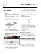
UDM-0404 Multi-Format Distribution Hub
Overview
The UDM-0404 Endeleo Multi-format Distribution Hub (FG-UDM-0404C) delivers any video source,
including Component, RGB, VGA and S-Video to a virtually unlimited number of display devices
(FIG. 1).
The UDM-0404 supports four high-resolution input ports and four UDM output ports, and supports
multiple methods of delivering sync information between the UDM Hub and the display device,
including common mode.
The UDM-0404 delivers media over easily-installed, dedicated Cat5/5e/6, which de-couples distribution
of the media from the corporate backbone. Users can quickly switch and transmit any video source to the
display device, power on/off display devices, and permission user control to select and play video
sources and media servers on demand.
The UDM-0404 offers four high-resolution input ports on the back of each unit. In total, the UDM-0404
system can distribute any combination of the following: four RGBHV sources, four Component video
sources, four S-Video sources or 12 Composite video sources.
Source inputs to the UDM are industry standard VGA, Composite, Component or S-Video feed, and
output is presented as an RJ45 port for connection to Cat5, 5e or 6 twisted-pair Ethernet cable.
Video inputs are connected via the HD15 Input connector on the rear of the UDM. Adapters are used to
bring the different types of video source into the UDM. See the Audio & Video Formats/Resolutions/
Distance section on page 12 for tested and confirmed distances.
Each UDM has an Ethernet network port to provide connectivity to a central management system, or can
be controlled by the onboard configuration pages. A Serial connection is also provided for CLI
administration and diagnostic purposes.
Features
4 multi-format inputs x 4 outputs
Supports multiple methods of delivering sync, including Common Mode Sync delivery
Digital audio support
Central device control
1U rack-mounting
FIG. 1 UDM-0404

UDM-0404 Multi-Format Distribution Hub
2
UDM-0404 Endeleo Multi-Format Distribution Hub
Compatibility
The UDM-0404 is compatible for use with UDM-RX01 (FG-UDM-RX01) and UDM-RX02
(FG-UDM-RX02) Receivers.
Product Specifications
Common Mode Sync delivery is supported only on the UDM-RX02.
UDM-0404 Specifications
Power Requirements: • 90-264V AC, 50/60Hz
• Max power consumption: 130W
Front Panel Components
IR Sensor: Infrared receive port (IRRX) for learning IR remote control functions from IR con-
trolled devices.
Outputs: 4 RJ-45 ports for connection to Endeleo UDM-RX02 Receivers (via Cat5, Cat5e
or Cat6).
Rear Panel Components
Network Port: RJ-12 10 BaseT network port is provides network connectivity.
Serial Port: RJ-12 port allows an administrator to control various functions from a command
line prompt.
IRTX Ports: 2 Infrared Transmit (IRTX) ports allow the UDM-0404 to control IR devices via IR
emitters attached to the UDM. The IR cable is attached to the IR panel of the con-
trolled device to receive IR commands issued through the software or remote
control.
Input Connectors (A-D): 4 sets of Input connections for up to 4 A/V inputs with the following connectors:
• Video
• Audio Left
• Audio Right
• SPDIF
IEC Power Connector: Universal switch-mode power supply.
• As a Class 1 appliance the UDM-0404 should be connected to a mains supply
with a protective earthing connection.
• The Power On/Off switch is located beside the IEC power connector.
Note: The rating label found beneath the IEC connector contains important
information applicable to the UDM-0404’s installation environment.
Network Interface: 10baseT
Serial Interface: 9600, 8, N, 1
Max Video Input: • 4 x RGBHV (or)
• 4 x S-Video (or)
• 12 x CVBS (plus)
Operating Environment: • 35°F - 95°F (5°C - 35°C)
• Max. relative humidity - 85% (non-condensing)
Dimensions (HWD):
1 3/4" x 19" x 12 1/2" (45 mm x 440 mm x 320 mm)
Weight:
8.8 lb. (4 Kg)
Certifications: • CE/UL/FCC part 15 Class A

UDM-0404 Multi-Format Distribution Hub
3
UDM-0404 Endeleo Multi-Format Distribution Hub
UDM-0404 Specifications (Cont.)
Included Accessories: • IEC power cord
• 19" mounting brackets
• RS-232 DB-9/RJ-12 connection cable
Note: No A/V interface cables supplied.
Other AMX Equipment: • HD15 to S-Video Cable (FG-UDM-SVID01)
• HD15 to 3x RCA Breakout Cable (FG-HD15RCA3)
• RS232 DB9/RJ12 Connection Cable (FG-RS01)
• UDM-RX02 Multi-Format Receiver (FG-UDM-RX02)
• UDM-RC10 IR Engineering Remote Control (FG-UDM-RC10)
• IR01 IR Emitter Module (FG-IR01)
• IR02 Endeleo IR Splitter Cable (FG-IR02)
• IR03 External IR Receiver Module (FG-IR03)

UDM-0404 Multi-Format Distribution Hub
4
UDM-0404 Endeleo Multi-Format Distribution Hub

Installation
5
UDM-0404 Endeleo Multi-Format Distribution Hub
Installation
Overview
The UDM-0404 occupies a single rack space in a standard 19" equipment rack. Rack-mounting brackets
and screws are located in the accessories box supplied with the UDM-0404.
1. Attach the rack-mounting brackets to each side of the UDM-0404 using four M4 screws for each
bracket (FIG. 2).
2. Place the UDM-0404 in the rack and hold steady.
3. Two fixing holes are supplied on each side of the UDM-0404. Secure the UDM-0404 into the rack
using the fixing holes (FIG. 3).
Ventilation
ALWAYS ensure that the rack enclosure is adequately ventilated.
Sufficient airflow must be achieved (by convection or forced-air cooling) to satisfy the ventilation
requirements of all the items of equipment installed within the rack.
Exercise extreme care when lifting or moving the UDM-0404 within the rack to avoid
injury. It is recommended that you seek the assistance of another person when rack
mounting the 0404.
FIG. 2 Attach the mounting brackets to each side of the UDM-0404
To prevent injury the UDM-0404 must be securely attached to the rack in accordance
with the installation instructions.
ALWAYS use the special rack mount brackets supplied and high quality fixing screws
to ensure the UDM-0404 is installed in the rack correctly.
FIG. 3 Secure the UDM-0404 into the rack using the fixing holes
DO NOT stand other units directly on top of the UDM-0404 when it is rack mounted,
as this will place excessive strain on the mounting brackets.

Installation
6
UDM-0404 Endeleo Multi-Format Distribution Hub

Wiring and Connections
7
UDM-0404 Endeleo Multi-Format Distribution Hub
Wiring and Connections
UDM-0404 Front Panel Components
The components on the front panel of the UDM-0404 are described below (FIG. 4).
IR Learning Sensor
An IR receive port is found at the front of the UDM-0404 to the left-hand side (see FIG. 4). This is used
to learn device IR remote control functions from devices such as DVD players, VCRs etc. Common
functions learned include Power on, Power off, Play, Pause, Stop, etc.
Refer to the Configuration - Protocols Page section on page 63 for details.
OUTPUT Ports (RJ-45)
The four RJ-45 ports on the front panel of the UDM (labelled “1-4”) provide connectivity to
UDM-RX02 Multi-Format Receivers. This is a standard RJ-45 connector, and UDM Receivers can be
connected via either Cat5, Cat5e or Cat6 cabling (FIG. 5).
UDM Port Pinouts
The following table describes the pinout configuration of the UDM ports:
FIG. 4 UDM-0404 - Front Panel Components
FIG. 5 RJ-45 Pinouts
UDM Port Pinouts
Pair Color RJ45 Pin Polarity Endeleo Function
1
White / Blue 5 -
Green
Blue 4 +
2
White / Orange 1 +
Red
Orange 2 -
3
White / Green 3 +
Blue
Green 6 -
4
White / Brown 7 +
Bi-Directional Control, Digital Audio, Phantom Power
Brown 8 -, Gnd
IR Learning Sensor
4 RJ45 Output Ports for connection
to UDM-RX02 Receivers

Wiring and Connections
8
UDM-0404 Endeleo Multi-Format Distribution Hub
UDM Port Transmission Details
The following table provides transmission details for the UDM port:
An incorrectly terminated cable will result in the following scenarios:
UDM-0404 Rear Panel Components
FIG. 6 shows the components on the rear panel:
Transmission on UDM Port
Pair Pin UDM (CVBS) UDM (SVideo) UDM (YPbPr) UDM (RGB)
1 1 CVBS + Luma + Y+ Red +
1 2 CVBS - Luma - Y- Red -
2 3 Chroma + Pr+ Blue+
3 4 Pb+ Green +
3 5 Pb- Green -
2 6 Chroma - Pr- Blue -
4 7 Power, Data, Audio Power, Data, Audio Power, Data, Audio Power, Data, Audio
4 8 Power, Data, Audio Power, Data, Audio Power, Data, Audio Power, Data, Audio
Incorrectly terminated cable results
Pair Composite
Video
SVideo Component
Video
RGBHV
Video
User Port
LINK LED
1 No Video 1 No Luma No Y No RED LIT
2 No Video 3 No Chroma No Pr No BLUE LIT
3 No Video 2 NONE No Pb NONE No GREEN
NONE
LIT NONE
4
FIG. 6
UDM-0404 - rear panel components
Input connections
TX connections for locally connected devices
ETHERNET port (RJ-45)
Serial port (RJ-12)
IEC Power cable
connector/switch
(A - D)
The "Cascade In/Out" ports on the UDM-0404 are reserved for future
implementation.
/